Page 61 of 345

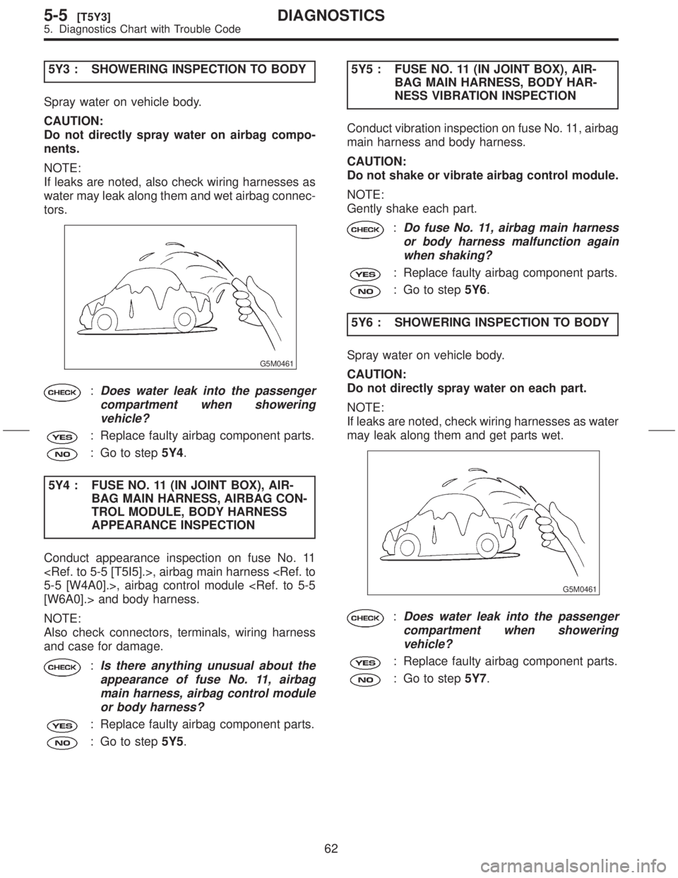
5Y3 : SHOWERING INSPECTION TO BODY
Spray water on vehicle body.
CAUTION:
Do not directly spray water on airbag compo-
nents.
NOTE:
If leaks are noted, also check wiring harnesses as
water may leak along them and wet airbag connec-
tors.
G5M0461
:Does water leak into the passenger
compartment when showering
vehicle?
: Replace faulty airbag component parts.
: Go to step5Y4.
5Y4 : FUSE NO. 11 (IN JOINT BOX), AIR-
BAG MAIN HARNESS, AIRBAG CON-
TROL MODULE, BODY HARNESS
APPEARANCE INSPECTION
Conduct appearance inspection on fuse No. 11
, airbag main harness
5-5 [W4A0].>, airbag control module
[W6A0].> and body harness.
NOTE:
Also check connectors, terminals, wiring harness
and case for damage.
:Is there anything unusual about the
appearance of fuse No. 11, airbag
main harness, airbag control module
or body harness?
: Replace faulty airbag component parts.
: Go to step5Y5.5Y5 : FUSE NO. 11 (IN JOINT BOX), AIR-
BAG MAIN HARNESS, BODY HAR-
NESS VIBRATION INSPECTION
Conduct vibration inspection on fuse No. 11, airbag
main harness and body harness.
CAUTION:
Do not shake or vibrate airbag control module.
NOTE:
Gently shake each part.
:Do fuse No. 11, airbag main harness
or body harness malfunction again
when shaking?
: Replace faulty airbag component parts.
: Go to step5Y6.
5Y6 : SHOWERING INSPECTION TO BODY
Spray water on vehicle body.
CAUTION:
Do not directly spray water on each part.
NOTE:
If leaks are noted, check wiring harnesses as water
may leak along them and get parts wet.
G5M0461
:Does water leak into the passenger
compartment when showering
vehicle?
: Replace faulty airbag component parts.
: Go to step5Y7.
62
5-5[T5Y3]DIAGNOSTICS
5. Diagnostics Chart with Trouble Code
Page 89 of 345

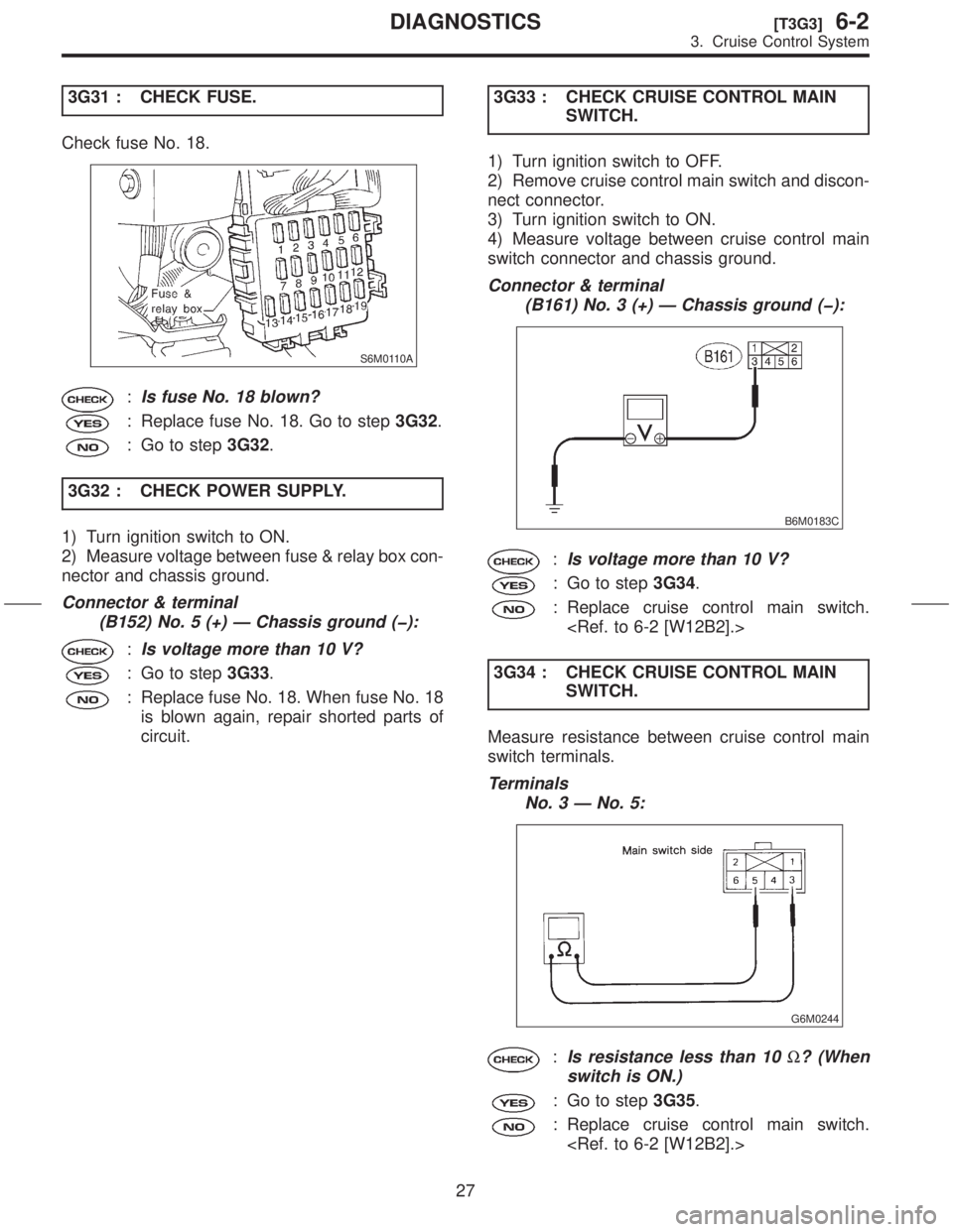
3G31 : CHECK FUSE.
Check fuse No. 18.
S6M0110A
:Is fuse No. 18 blown?
: Replace fuse No. 18. Go to step3G32.
: Go to step3G32.
3G32 : CHECK POWER SUPPLY.
1) Turn ignition switch to ON.
2) Measure voltage between fuse & relay box con-
nector and chassis ground.
Connector & terminal
(B152) No. 5 (+) Ð Chassis ground (þ):
:Is voltage more than 10 V?
: Go to step3G33.
: Replace fuse No. 18. When fuse No. 18
is blown again, repair shorted parts of
circuit.3G33 : CHECK CRUISE CONTROL MAIN
SWITCH.
1) Turn ignition switch to OFF.
2) Remove cruise control main switch and discon-
nect connector.
3) Turn ignition switch to ON.
4) Measure voltage between cruise control main
switch connector and chassis ground.
Connector & terminal
(B161) No. 3 (+) Ð Chassis ground (þ):
B6M0183C
:Is voltage more than 10 V?
: Go to step3G34.
: Replace cruise control main switch.
3G34 : CHECK CRUISE CONTROL MAIN
SWITCH.
Measure resistance between cruise control main
switch terminals.
Terminals
No. 3 Ð No. 5:
G6M0244
:Is resistance less than 10W? (When
switch is ON.)
: Go to step3G35.
: Replace cruise control main switch.
27
[T3G3]6-2DIAGNOSTICS
3. Cruise Control System
Page 105 of 345

3H51 : CHECK POWER SUPPLY.
1) Turn ignition switch to ON.
2) Turn cruise control main switch to ON.
3) Set select monitor in ªCurrent Data Display &
Saveº mode.
4) Check signals for proper operation.
(1) When pushing the SET/COAST switch:
The SET/COAST switch shown on the display
turns from ªOFFº to ªONº.
(2) When pushing the RESUME/ACCEL
switch:
The RESUME/ACCEL switch shown on the dis-
play turns from ªOFFº to ªONº.
5) Turn ignition switch to OFF.
6) Disconnect connector from cruise control com-
mand switch.
7) Turn ignition switch to ON.
8) Measure voltage between cruise control com-
mand switch connector and chassis ground.
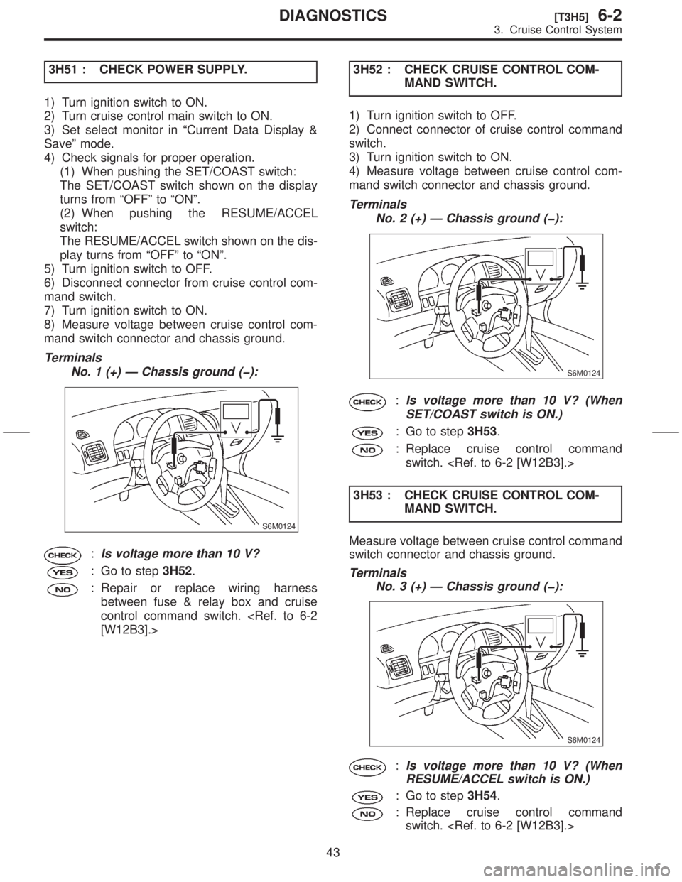
Terminals
No. 1 (+) Ð Chassis ground (þ):
S6M0124
:Is voltage more than 10 V?
: Go to step3H52.
: Repair or replace wiring harness
between fuse & relay box and cruise
control command switch.
[W12B3].>3H52 : CHECK CRUISE CONTROL COM-
MAND SWITCH.
1) Turn ignition switch to OFF.
2) Connect connector of cruise control command
switch.
3) Turn ignition switch to ON.
4) Measure voltage between cruise control com-
mand switch connector and chassis ground.
Terminals
No. 2 (+) Ð Chassis ground (þ):
S6M0124
:Is voltage more than 10 V? (When
SET/COAST switch is ON.)
: Go to step3H53.
: Replace cruise control command
switch.
3H53 : CHECK CRUISE CONTROL COM-
MAND SWITCH.
Measure voltage between cruise control command
switch connector and chassis ground.
Terminals
No. 3 (+) Ð Chassis ground (þ):
S6M0124
:Is voltage more than 10 V? (When
RESUME/ACCEL switch is ON.)
: Go to step3H54.
: Replace cruise control command
switch.
43
[T3H5]6-2DIAGNOSTICS
3. Cruise Control System
Page 117 of 345
4B212 : CHECK FOR UNCHECKED TRANS-
MITTER.
Check for an unchecked transmitter.
:Does an unchecked transmitter
exist?
: Check for an unchecked transmitter. Go
to step4B21.
: Go to step4B31.
3. FUSE
4B31 : CHECK FUSE.
Remove and visually check the fuse No. 3 (in fuse
box).
:Is fuse No. 3 blown?
: Replace fuse (15 A).
: Go to step4B41.
55
[T4B3]6-2DIAGNOSTICS
4. Keyless Entry System
Page 118 of 345

4. POWER SUPPLY CIRCUIT
4B41 : CHECK POWER SUPPLY CIRCUIT.
Measure voltage between fuse box connector
(B158) and chassis ground.
Connector & terminal
(B158) No. 8 (+) Ð Chassis ground (þ):
B6M1344B
:Is the voltage more than 10 V?
: Go to step4B42.
: Repair wiring harness between fuse box
and battery.
4B42 : CHECK POWER SUPPLY CIRCUIT.
1) Disconnect connector from keyless entry con-
trol module.
2) Measure voltage between keyless entry control
module connector (B176) and chassis ground.
Connector & terminal
(B176) No. 3 (+) Ð Chassis ground (þ):
B6M0952A
:Is the voltage more than 10 V?
: Go to step4B51.
: Repair wiring harness between keyless
entry control module and fuse box.
5. GROUND CIRCUIT
4B51 : CHECK GROUND CIRCUIT.
Measure resistance between keyless entry control
module connector (B176) and chassis ground.
Connector & terminal
(B176) No. 8 (+) Ð Chassis ground (þ):
B6M0953A
:Is the resistance less than 10W?
: Go to step4F11.
: Repair wiring harness between keyless
entry control module and chassis
ground.
56
6-2[T4B4]DIAGNOSTICS
4. Keyless Entry System
Page 119 of 345
C: ELECTRICAL COMPONENTS LOCATION
S6M0450A
(1) Horn
(2) Keyless entry control module(3) Horn relay (in main fuse box)
(4) Rear gate latch switch(5) Door switch
57
[T4C0]6-2DIAGNOSTICS
4. Keyless Entry System
Page 125 of 345

2. DIAGNOSTICS ITEM 1
4F21 : SELECT HORN SIGNAL OPERA-
TION.
Keep both LOCK/ARM and UNLOCK/DISARM
buttons pressed for more than 1.5 seconds.
:Does the horn chirp one time?
: Go to step4F22.
: Replace keyless entry control module.
4F22 : CHECK HORN SIGNAL OUTPUT
SIGNAL.
1) Disconnect connector from keyless entry con-
trol module.
2) Measure voltage between keyless entry control
module connector (B176) and chassis ground.
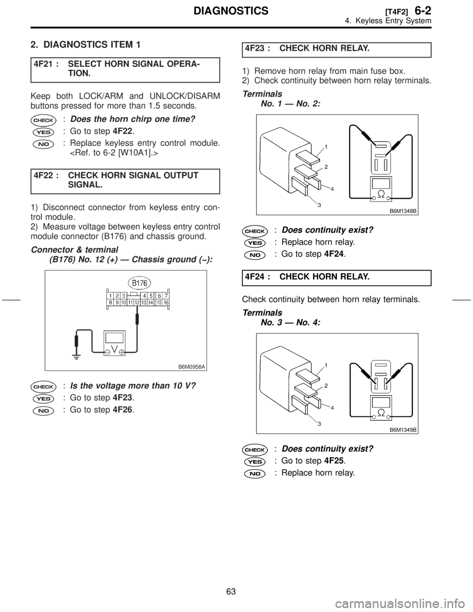
Connector & terminal
(B176) No. 12 (+) Ð Chassis ground (þ):
B6M0958A
:Is the voltage more than 10 V?
: Go to step4F23.
: Go to step4F26.4F23 : CHECK HORN RELAY.
1) Remove horn relay from main fuse box.
2) Check continuity between horn relay terminals.
Terminals
No. 1 Ð No. 2:
B6M1348B
:Does continuity exist?
: Replace horn relay.
: Go to step4F24.
4F24 : CHECK HORN RELAY.
Check continuity between horn relay terminals.
Terminals
No. 3 Ð No. 4:
B6M1349B
:Does continuity exist?
: Go to step4F25.
: Replace horn relay.
63
[T4F2]6-2DIAGNOSTICS
4. Keyless Entry System
Page 126 of 345
4F25 : CHECK HORN RELAY.
1) Connect the battery to horn relay terminals No.
3 and No. 4.
2) Check continuity between horn relay terminals.
Terminals
No. 1 Ð No. 2:
B6M1350B
:Does continuity exist?
: Repair wiring harness of horn circuit.
: Replace horn relay.
4F26 : CHECK FUSE.
Remove and visually check the fuse No. 6 (in main
fuse box).
:Is the fuse No. 6 blown?
: Replace fuse (15 A).
: Go to step4F27.4F27 : CHECK POWER SUPPLY FOR
HORN RELAY.
1) Install horn relay to main fuse box.
2) Measure voltage between main fuse box con-
nector (F37) and chassis ground.
Connector & terminal
(F37) No. 4 (+) Ð Chassis ground (þ):
B6M1351A
:Is the voltage more than 10 V?
: Go to step4F28.
: Repair wiring harness between main
fuse box and battery.
64
6-2[T4F2]DIAGNOSTICS
4. Keyless Entry System