1999 NISSAN PRIMERA sensor
[x] Cancel search: sensorPage 466 of 2267
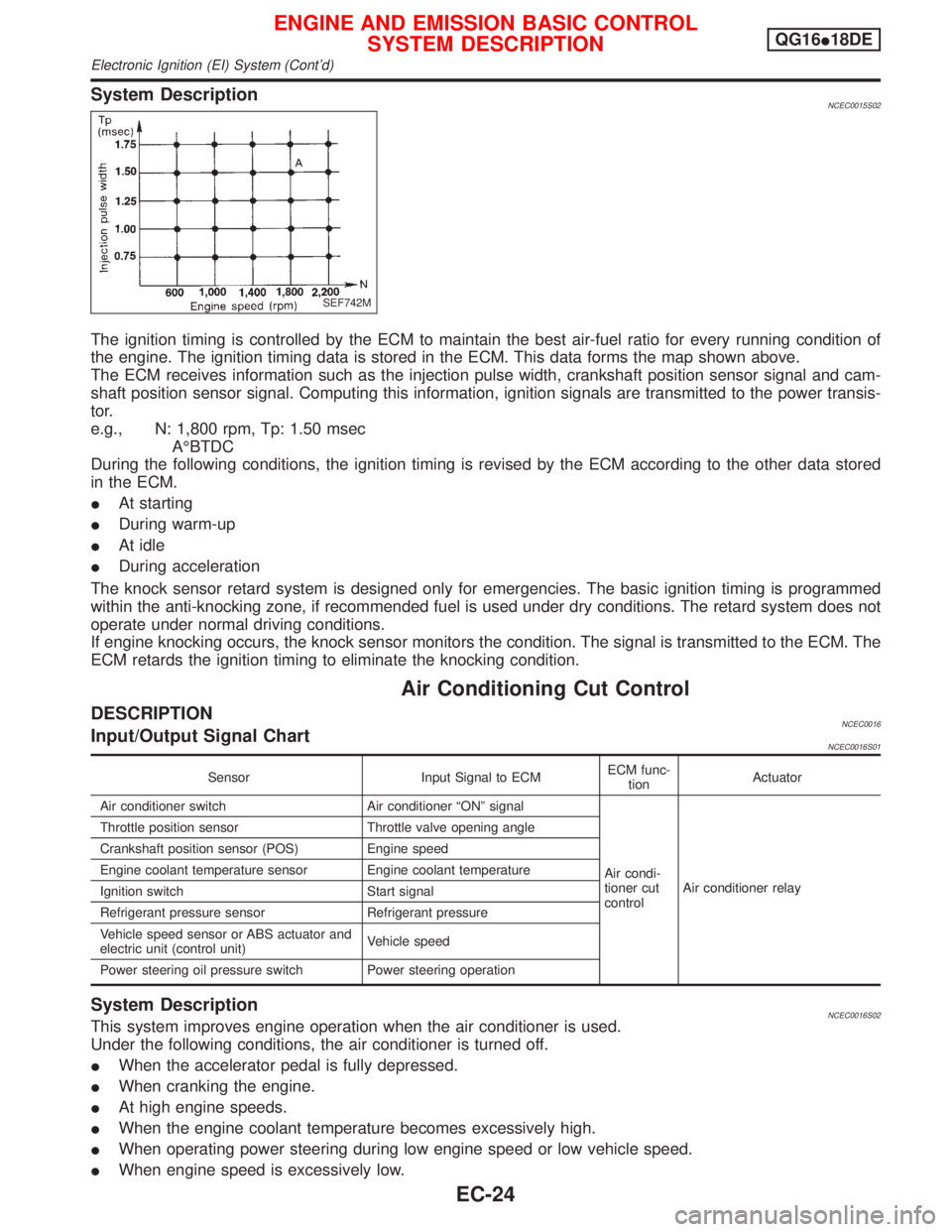
System DescriptionNCEC0015S02
The ignition timing is controlled by the ECM to maintain the best air-fuel ratio for every running condition of
the engine. The ignition timing data is stored in the ECM. This data forms the map shown above.
The ECM receives information such as the injection pulse width, crankshaft position sensor signal and cam-
shaft position sensor signal. Computing this information, ignition signals are transmitted to the power transis-
tor.
e.g., N: 1,800 rpm, Tp: 1.50 msec
AÉBTDC
During the following conditions, the ignition timing is revised by the ECM according to the other data stored
in the ECM.
IAt starting
IDuring warm-up
IAt idle
IDuring acceleration
The knock sensor retard system is designed only for emergencies. The basic ignition timing is programmed
within the anti-knocking zone, if recommended fuel is used under dry conditions. The retard system does not
operate under normal driving conditions.
If engine knocking occurs, the knock sensor monitors the condition. The signal is transmitted to the ECM. The
ECM retards the ignition timing to eliminate the knocking condition.
Air Conditioning Cut Control
DESCRIPTIONNCEC0016Input/Output Signal ChartNCEC0016S01
Sensor Input Signal to ECMECM func-
tionActuator
Air conditioner switch Air conditioner ªONº signal
Air condi-
tioner cut
controlAir conditioner relay Throttle position sensor Throttle valve opening angle
Crankshaft position sensor (POS) Engine speed
Engine coolant temperature sensor Engine coolant temperature
Ignition switch Start signal
Refrigerant pressure sensor Refrigerant pressure
Vehicle speed sensor or ABS actuator and
electric unit (control unit)Vehicle speed
Power steering oil pressure switch Power steering operation
System DescriptionNCEC0016S02This system improves engine operation when the air conditioner is used.
Under the following conditions, the air conditioner is turned off.
IWhen the accelerator pedal is fully depressed.
IWhen cranking the engine.
IAt high engine speeds.
IWhen the engine coolant temperature becomes excessively high.
IWhen operating power steering during low engine speed or low vehicle speed.
IWhen engine speed is excessively low.
SEF742M
ENGINE AND EMISSION BASIC CONTROL
SYSTEM DESCRIPTIONQG16I18DE
Electronic Ignition (EI) System (Cont'd)
EC-24
Page 467 of 2267
Fuel Cut Control (at no load & high engine
speed)
DESCRIPTIONNCEC0017Input/Output Signal ChartNCEC0017S01
Sensor Input Signal to ECMECM func-
tionActuator
Vehicle speed sensor or ABS actuator and
electric unit (control unit)Vehicle speed
Fuel cut
controlInjectors PNP switch Neutral position
Throttle position sensor Throttle position
Engine coolant temperature sensor Engine coolant temperature
Crankshaft position sensor (POS) Engine speed
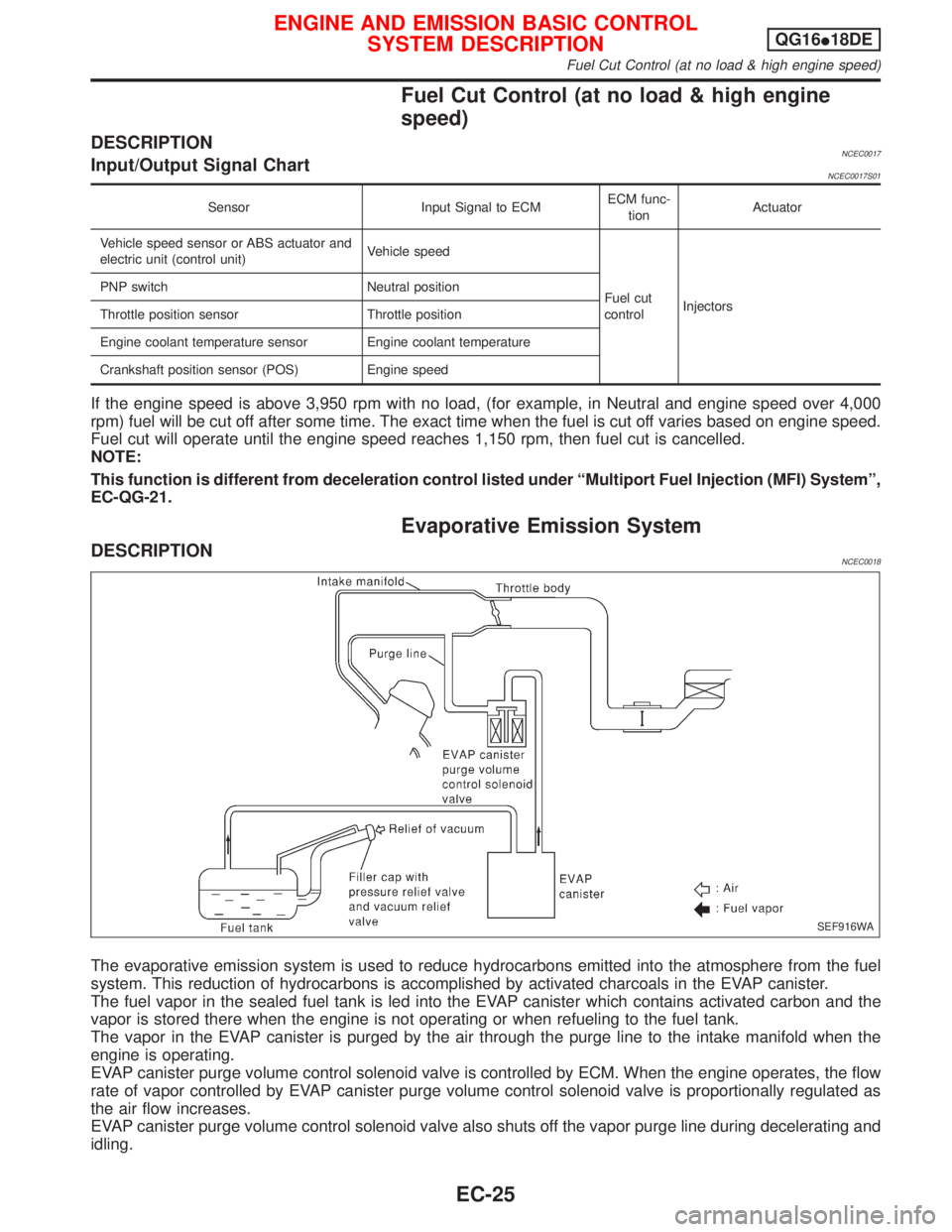
If the engine speed is above 3,950 rpm with no load, (for example, in Neutral and engine speed over 4,000
rpm) fuel will be cut off after some time. The exact time when the fuel is cut off varies based on engine speed.
Fuel cut will operate until the engine speed reaches 1,150 rpm, then fuel cut is cancelled.
NOTE:
This function is different from deceleration control listed under ªMultiport Fuel Injection (MFI) Systemº,
EC-QG-21.
Evaporative Emission System
DESCRIPTIONNCEC0018
The evaporative emission system is used to reduce hydrocarbons emitted into the atmosphere from the fuel
system. This reduction of hydrocarbons is accomplished by activated charcoals in the EVAP canister.
The fuel vapor in the sealed fuel tank is led into the EVAP canister which contains activated carbon and the
vapor is stored there when the engine is not operating or when refueling to the fuel tank.
The vapor in the EVAP canister is purged by the air through the purge line to the intake manifold when the
engine is operating.
EVAP canister purge volume control solenoid valve is controlled by ECM. When the engine operates, the flow
rate of vapor controlled by EVAP canister purge volume control solenoid valve is proportionally regulated as
the air flow increases.
EVAP canister purge volume control solenoid valve also shuts off the vapor purge line during decelerating and
idling.
SEF916WA
ENGINE AND EMISSION BASIC CONTROL
SYSTEM DESCRIPTIONQG16I18DE
Fuel Cut Control (at no load & high engine speed)
EC-25
Page 476 of 2267
5. Turn ignition switch ªOFFº and wait at least 9 seconds.
6. Start the engine and let it to idle for at least 28 seconds.
7. Select ªIDLE AIR VOL LEARNº in ªWORK SUPPORTº mode.
8. Touch ªSTARTº and wait 20 seconds.
9. Make sure that ªCMPLTº is displayed on CONSULT-II screen.
If ªINCMPº is displayed, ªIdle Air Volume Learningº will not be
carried out successfully. In this case, find the cause of the
problem by referring to the NOTE below.
10. Rev up the engine two or three times. Make sure that idle
speed and ignition timing are close to or within specifications.
ITEM SPECIFICATION
Idle speed 700 50 rpm
Ignition timing 8É 5É BTDC
Without CONSULT-IINCEC0541S02021. Turn ignition switch ªONº and wait at least 1 second.
2. Turn ignition switch ªOFFº and wait at least 9 seconds.
3. Start the engine and warm it up to normal operating tempera-
ture.
4. Check that all items listed under the topic ªPRE-CONDITION-
INGº (previously mentioned) are in good order.
5. Turn ignition switch ªOFFº and wait at least 9 seconds.
6. Start the engine and let it to idle for at least 28 seconds.
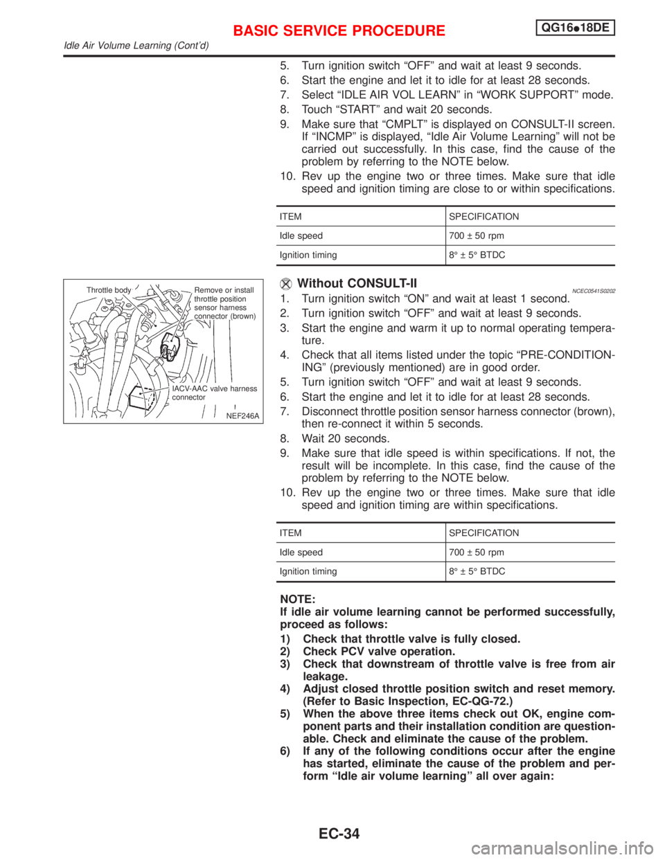
7. Disconnect throttle position sensor harness connector (brown),
then re-connect it within 5 seconds.
8. Wait 20 seconds.
9. Make sure that idle speed is within specifications. If not, the
result will be incomplete. In this case, find the cause of the
problem by referring to the NOTE below.
10. Rev up the engine two or three times. Make sure that idle
speed and ignition timing are within specifications.
ITEM SPECIFICATION
Idle speed 700 50 rpm
Ignition timing 8É 5É BTDC
NOTE:
If idle air volume learning cannot be performed successfully,
proceed as follows:
1) Check that throttle valve is fully closed.
2) Check PCV valve operation.
3) Check that downstream of throttle valve is free from air
leakage.
4) Adjust closed throttle position switch and reset memory.
(Refer to Basic Inspection, EC-QG-72.)
5) When the above three items check out OK, engine com-
ponent parts and their installation condition are question-
able. Check and eliminate the cause of the problem.
6) If any of the following conditions occur after the engine
has started, eliminate the cause of the problem and per-
form ªIdle air volume learningº all over again:
NEF246A Throttle body
.Remove or install
throttle position
sensor harness
connector (brown)
IACV-AAC valve harness
connector
BASIC SERVICE PROCEDUREQG16I18DE
Idle Air Volume Learning (Cont'd)
EC-34
Page 478 of 2267
IntroductionNCEC0029The ECM has an on board diagnostic system which detects malfunctions related to engine sensors or actua-
tors. The ECM also records various emission-related diagnostic information including:
Diagnostic Trouble Code (DTC) Mode 3 of ISO15031-5
Freeze Frame data Mode 2 of ISO15031-5
System Readiness Test (SRT) code Mode 1 of ISO15031-5
1st Trip Diagnostic Trouble Code (1st Trip DTC) Mode 7 of ISO15031-5
1st Trip Freeze Frame data
Test values and Test limits Mode 6 of ISO15031-5
Calibration ID Mode 9 of ISO15031-5
The above information can be checked using procedures listed in the table below.
X: Applicable Ð: Not applicable
DTC 1st trip DTCFreeze Frame
data1st trip Freeze
Frame dataSRT code Test value
ECM*3 X X*1ÐÐÐÐ
CONSULT-II*4XXXXXÐ
GST*4 X X*2 X Ð X X
*1: When DTC and 1st trip DTC simultaneously appear on the display, they cannot be clearly distinguished from each other.
*2: 1st trip DTCs for self-diagnoses concerning SRT items cannot be shown on the GST display.
*3: In diagnostic test mode II (Self-diagnostic results), DTC is displayed on MI. DTC uses a set of four digit numbers.
*4: In SELF-DIAGNOSTIC RESULTS mode, DTC is displayed. DTC uses ªPº and a set of four digit numbers.
The malfunction indicator (MI) on the instrument panel lights up when the same malfunction is detected in two
consecutive trips (Two trip detection logic), or when the ECM enters fail-safe mode. (Refer to EC-QG-81.)
Two Trip Detection LogicNCEC0030When a malfunction is detected for the first time, 1st trip DTC and 1st trip Freeze Frame data are stored in
the ECM memory. The MI will not light up at this stage <1st trip>.
If the same malfunction is detected again during the next drive, the DTC and Freeze Frame data are stored
in the ECM memory, and the MI lights up. The MI lights up at the same time when the DTC is stored <2nd
trip>. The ªtripº in the ªTwo Trip Detection Logicº means a driving mode in which self-diagnosis is performed
during vehicle operation. Specific on board diagnostic items will cause the ECM to light up or blink the MI,
and store DTC and Freeze Frame data, even in the 1st trip, as shown below.
X: Applicable Ð: Not applicable
ItemsMI DTC 1st trip DTC
1st trip 2nd trip
1st trip
displaying2nd trip
displaying1st trip
displaying2nd trip
displaying
BlinkingLighting
upBlinkingLighting
up
Misfire (Possible three way
catalyst damage)
Ð DTC: P0300 - P0304
(0300 - 0304) is being
detectedX ÐÐÐÐÐ X Ð
Misfire (Possible three way
catalyst damage)
Ð DTC: P0300 - P0304
(0300 - 0304) is being
detectedÐÐXÐÐXÐÐ
Fail-safe items (Refer to
EC-QG-81.)Ð X Ð Ð X*1 Ð X*1 Ð
Except above Ð ÐÐXÐX X X
*1: Except ªECMº.
ON BOARD DIAGNOSTIC SYSTEM DESCRIPTIONQG16I18DE
Introduction
EC-36
Page 480 of 2267
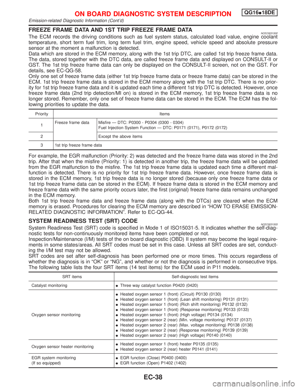
FREEZE FRAME DATA AND 1ST TRIP FREEZE FRAME DATANCEC0031S02The ECM records the driving conditions such as fuel system status, calculated load value, engine coolant
temperature, short term fuel trim, long term fuel trim, engine speed, vehicle speed and absolute pressure
sensor at the moment a malfunction is detected.
Data which are stored in the ECM memory, along with the 1st trip DTC, are called 1st trip freeze frame data.
The data, stored together with the DTC data, are called freeze frame data and displayed on CONSULT-II or
GST. The 1st trip freeze frame data can only be displayed on the CONSULT-II screen, not on the GST. For
details, see EC-QG-58.
Only one set of freeze frame data (either 1st trip freeze frame data or freeze frame data) can be stored in the
ECM. 1st trip freeze frame data is stored in the ECM memory along with the 1st trip DTC. There is no prior-
ity for 1st trip freeze frame data and it is updated each time a different 1st trip DTC is detected. However, once
freeze frame data (2nd trip detection/MI on) is stored in the ECM memory, 1st trip freeze frame data is no
longer stored. Remember, only one set of freeze frame data can be stored in the ECM. The ECM has the fol-
lowing priorities to update the data.
Priority Items
1Freeze frame data Misfire Ð DTC: P0300 - P0304 (0300 - 0304)
Fuel Injection System Function Ð DTC: P0171 (0171), P0172 (0172)
2 Except the above items
3 1st trip freeze frame data
For example, the EGR malfunction (Priority: 2) was detected and the freeze frame data was stored in the 2nd
trip. After that when the misfire (Priority: 1) is detected in another trip, the freeze frame data will be updated
from the EGR malfunction to the misfire. The 1st trip freeze frame data is updated each time a different mal-
function is detected. There is no priority for 1st trip freeze frame data. However, once freeze frame data is
stored in the ECM memory, 1st trip freeze data is no longer stored (because only one freeze frame data or
1st trip freeze frame data can be stored in the ECM). If freeze frame data is stored in the ECM memory and
freeze frame data with the same priority occurs later, the first (original) freeze frame data remains unchanged
in the ECM memory.
Both 1st trip freeze frame data and freeze frame data (along with the DTCs) are cleared when the ECM
memory is erased. Procedures for clearing the ECM memory are described in ªHOW TO ERASE EMISSION-
RELATED DIAGNOSTIC INFORMATIONº. Refer to EC-QG-44.
SYSTEM READINESS TEST (SRT) CODENCEC0031S03System Readiness Test (SRT) code is specified in Mode 1 of ISO15031-5. It indicates whether the self-diag-
nostic tests for non-continuously monitored items have been completed or not.
Inspection/Maintenance (I/M) tests of the on board diagnostic (OBD) II system may become the legal require-
ments in some states/areas. All SRT codes must be set in this case. Unless all SRT codes are set, conduct-
ing the I/M test may not be allowed.
SRT codes are set after self-diagnosis has been performed one or more times. This occurs regardless of
whether the diagnosis is in ªOKº or ªNGº, and whether or not the diagnosis is performed in consecutive trips.
The following table lists the four SRT items (14 test items) for the ECM used in P11 models.
SRT items Self-diagnostic test items
Catalyst monitoringIThree way catalyst function P0420 (0420)
Oxygen sensor monitoringIHeated oxygen sensor 1 (front) (Circuit) P0130 (0130)
IHeated oxygen sensor 1 (front) (Lean shift monitoring) P0131 (0131)
IHeated oxygen sensor 1 (front) (Rich shift monitoring) P0132 (0132)
IHeated oxygen sensor 1 (front) (Response monitoring) P0133 (0133)
IHeated oxygen sensor 1 (front) (High voltage) P0134 (0134)
IHeated oxygen sensor 2 (rear) (Min. voltage monitoring) P0137 (0137)
IHeated oxygen sensor 2 (rear) (Max. voltage monitoring) P0138 (0138)
IHeated oxygen sensor 2 (rear) (Response monitoring) P0139 (0139)
IHeated oxygen sensor 2 (rear) (High voltage) P0140 (0140)
Oxygen sensor heater monitoringIHeated oxygen sensor 1 (front) heater P0135 (0135)
IHeated oxygen sensor 2 (rear) heater P0141 (0141)
EGR system monitoring
(If so equipped)IEGR function (Close) P0400 (0400)
IEGR function (Open) P1402 (1402)
ON BOARD DIAGNOSTIC SYSTEM DESCRIPTIONQG16I18DE
Emission-related Diagnostic Information (Cont'd)
EC-38
Page 484 of 2267
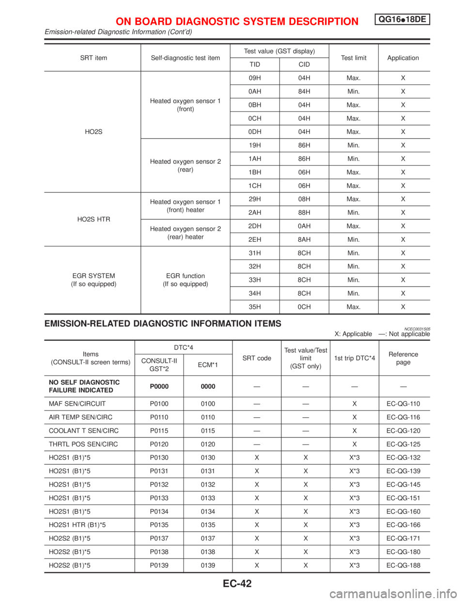
SRT item Self-diagnostic test itemTest value (GST display)
Test limit Application
TID CID
HO2SHeated oxygen sensor 1
(front)09H 04H Max. X
0AH 84H Min. X
0BH 04H Max. X
0CH 04H Max. X
0DH 04H Max. X
Heated oxygen sensor 2
(rear)19H 86H Min. X
1AH 86H Min. X
1BH 06H Max. X
1CH 06H Max. X
HO2S HTRHeated oxygen sensor 1
(front) heater29H 08H Max. X
2AH 88H Min. X
Heated oxygen sensor 2
(rear) heater2DH 0AH Max. X
2EH 8AH Min. X
EGR SYSTEM
(If so equipped)EGR function
(If so equipped)31H 8CH Min. X
32H 8CH Min. X
33H 8CH Min. X
34H 8CH Min. X
35H 0CH Max. X
EMISSION-RELATED DIAGNOSTIC INFORMATION ITEMSNCEC0031S05X: Applicable Ð: Not applicable
Items
(CONSULT-II screen terms)DTC*4
SRT codeTest value/Test
limit
(GST only)1st trip DTC*4Reference
page CONSULT-II
GST*2ECM*1
NO SELF DIAGNOSTIC
FAILURE INDICATEDP0000 0000ÐÐÐÐ
MAF SEN/CIRCUIT P0100 0100 Ð Ð X EC-QG-110
AIR TEMP SEN/CIRC P0110 0110 Ð Ð X EC-QG-116
COOLANT T SEN/CIRC P0115 0115 Ð Ð X EC-QG-120
THRTL POS SEN/CIRC P0120 0120 Ð Ð X EC-QG-125
HO2S1 (B1)*5 P0130 0130 X X X*3 EC-QG-132
HO2S1 (B1)*5 P0131 0131 X X X*3 EC-QG-139
HO2S1 (B1)*5 P0132 0132 X X X*3 EC-QG-145
HO2S1 (B1)*5 P0133 0133 X X X*3 EC-QG-151
HO2S1 (B1)*5 P0134 0134 X X X*3 EC-QG-160
HO2S1 HTR (B1)*5 P0135 0135 X X X*3 EC-QG-166
HO2S2 (B1)*5 P0137 0137 X X X*3 EC-QG-171
HO2S2 (B1)*5 P0138 0138 X X X*3 EC-QG-180
HO2S2 (B1)*5 P0139 0139 X X X*3 EC-QG-188
ON BOARD DIAGNOSTIC SYSTEM DESCRIPTIONQG16I18DE
Emission-related Diagnostic Information (Cont'd)
EC-42
Page 488 of 2267
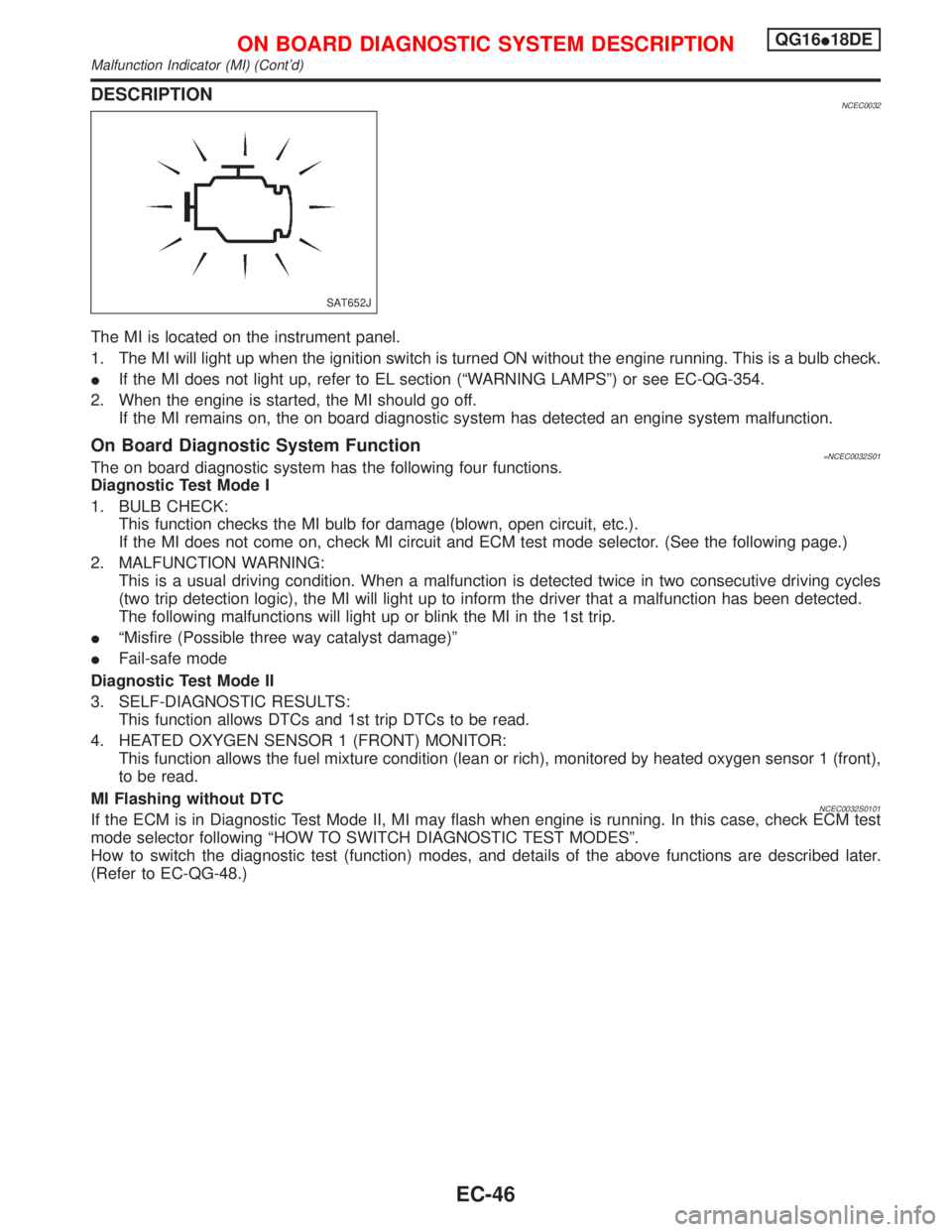
DESCRIPTIONNCEC0032
The MI is located on the instrument panel.
1. The MI will light up when the ignition switch is turned ON without the engine running. This is a bulb check.
IIf the MI does not light up, refer to EL section (ªWARNING LAMPSº) or see EC-QG-354.
2. When the engine is started, the MI should go off.
If the MI remains on, the on board diagnostic system has detected an engine system malfunction.
On Board Diagnostic System Function=NCEC0032S01The on board diagnostic system has the following four functions.
Diagnostic Test Mode I
1. BULB CHECK:
This function checks the MI bulb for damage (blown, open circuit, etc.).
If the MI does not come on, check MI circuit and ECM test mode selector. (See the following page.)
2. MALFUNCTION WARNING:
This is a usual driving condition. When a malfunction is detected twice in two consecutive driving cycles
(two trip detection logic), the MI will light up to inform the driver that a malfunction has been detected.
The following malfunctions will light up or blink the MI in the 1st trip.
IªMisfire (Possible three way catalyst damage)º
IFail-safe mode
Diagnostic Test Mode II
3. SELF-DIAGNOSTIC RESULTS:
This function allows DTCs and 1st trip DTCs to be read.
4. HEATED OXYGEN SENSOR 1 (FRONT) MONITOR:
This function allows the fuel mixture condition (lean or rich), monitored by heated oxygen sensor 1 (front),
to be read.
MI Flashing without DTC
NCEC0032S0101If the ECM is in Diagnostic Test Mode II, MI may flash when engine is running. In this case, check ECM test
mode selector following ªHOW TO SWITCH DIAGNOSTIC TEST MODESº.
How to switch the diagnostic test (function) modes, and details of the above functions are described later.
(Refer to EC-QG-48.)
SAT652J
ON BOARD DIAGNOSTIC SYSTEM DESCRIPTIONQG16I18DE
Malfunction Indicator (MI) (Cont'd)
EC-46
Page 489 of 2267
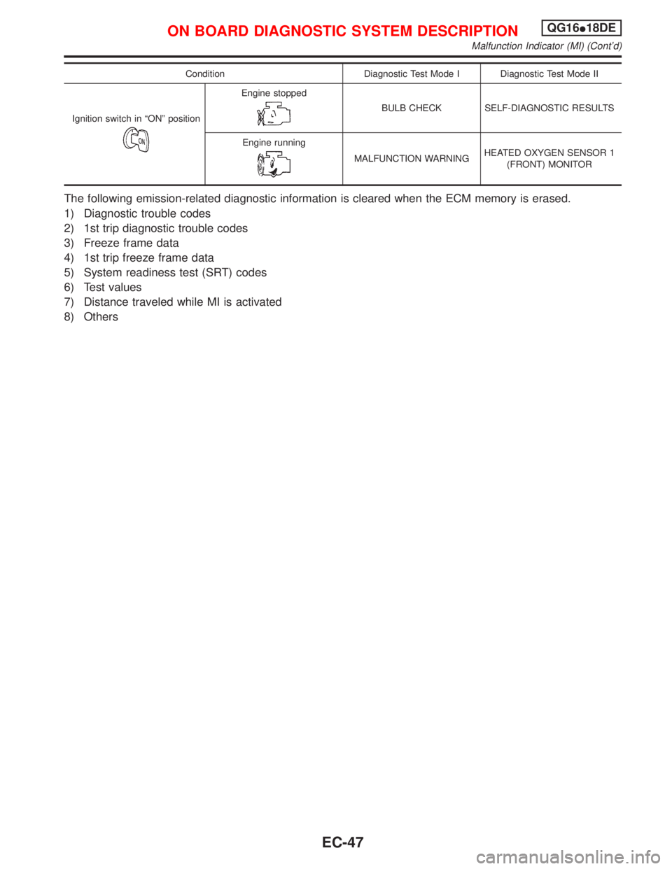
Condition Diagnostic Test Mode I Diagnostic Test Mode II
Ignition switch in ªONº position
Engine stopped
BULB CHECK SELF-DIAGNOSTIC RESULTS
Engine running
MALFUNCTION WARNINGHEATED OXYGEN SENSOR 1
(FRONT) MONITOR
The following emission-related diagnostic information is cleared when the ECM memory is erased.
1) Diagnostic trouble codes
2) 1st trip diagnostic trouble codes
3) Freeze frame data
4) 1st trip freeze frame data
5) System readiness test (SRT) codes
6) Test values
7) Distance traveled while MI is activated
8) Others
ON BOARD DIAGNOSTIC SYSTEM DESCRIPTIONQG16I18DE
Malfunction Indicator (MI) (Cont'd)
EC-47