1999 NISSAN PRIMERA engine overheat
[x] Cancel search: engine overheatPage 384 of 2267
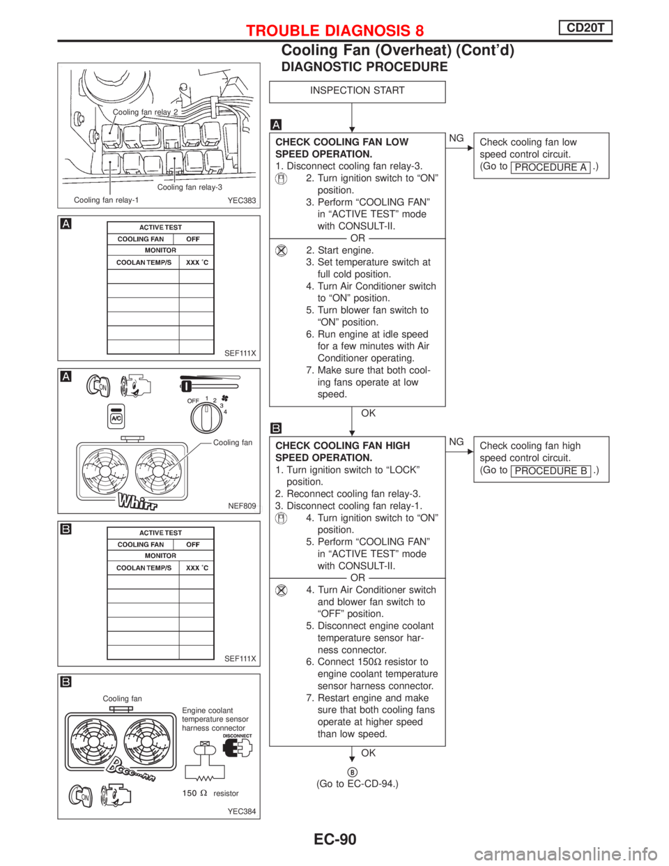
DIAGNOSTIC PROCEDURE
INSPECTION START
CHECK COOLING FAN LOW
SPEED OPERATION.
1. Disconnect cooling fan relay-3.
2. Turn ignition switch to ªONº
position.
3. Perform ªCOOLING FANº
in ªACTIVE TESTº mode
with CONSULT-II.
-------------------------------------------------------------------------------------------------------------------------OR-------------------------------------------------------------------------------------------------------------------------
2. Start engine.
3. Set temperature switch at
full cold position.
4. Turn Air Conditioner switch
to ªONº position.
5. Turn blower fan switch to
ªONº position.
6. Run engine at idle speed
for a few minutes with Air
Conditioner operating.
7. Make sure that both cool-
ing fans operate at low
speed.
OK
ENG
Check cooling fan low
speed control circuit.
(Go to
PROCEDURE A
.)
CHECK COOLING FAN HIGH
SPEED OPERATION.
1. Turn ignition switch to ªLOCKº
position.
2. Reconnect cooling fan relay-3.
3. Disconnect cooling fan relay-1.
4. Turn ignition switch to ªONº
position.
5. Perform ªCOOLING FANº
in ªACTIVE TESTº mode
with CONSULT-II.
-------------------------------------------------------------------------------------------------------------------------OR-------------------------------------------------------------------------------------------------------------------------
4. Turn Air Conditioner switch
and blower fan switch to
ªOFFº position.
5. Disconnect engine coolant
temperature sensor har-
ness connector.
6. Connect 150Wresistor to
engine coolant temperature
sensor harness connector.
7. Restart engine and make
sure that both cooling fans
operate at higher speed
than low speed.
OK
ENG
Check cooling fan high
speed control circuit.
(Go to
PROCEDURE B
.)
pB
(Go to EC-CD-94.)
.Cooling fan relay 2
Cooling fan relay-1Cooling fan relay-3
YEC383
SEF111X
NEF809
Cooling fan
SEF111X
YEC384
Cooling fan
Engine coolant
temperature sensor
harness connector
resistor
H
H
H
TROUBLE DIAGNOSIS 8CD20T
Cooling Fan (Overheat) (Cont'd)
EC-90
Page 388 of 2267
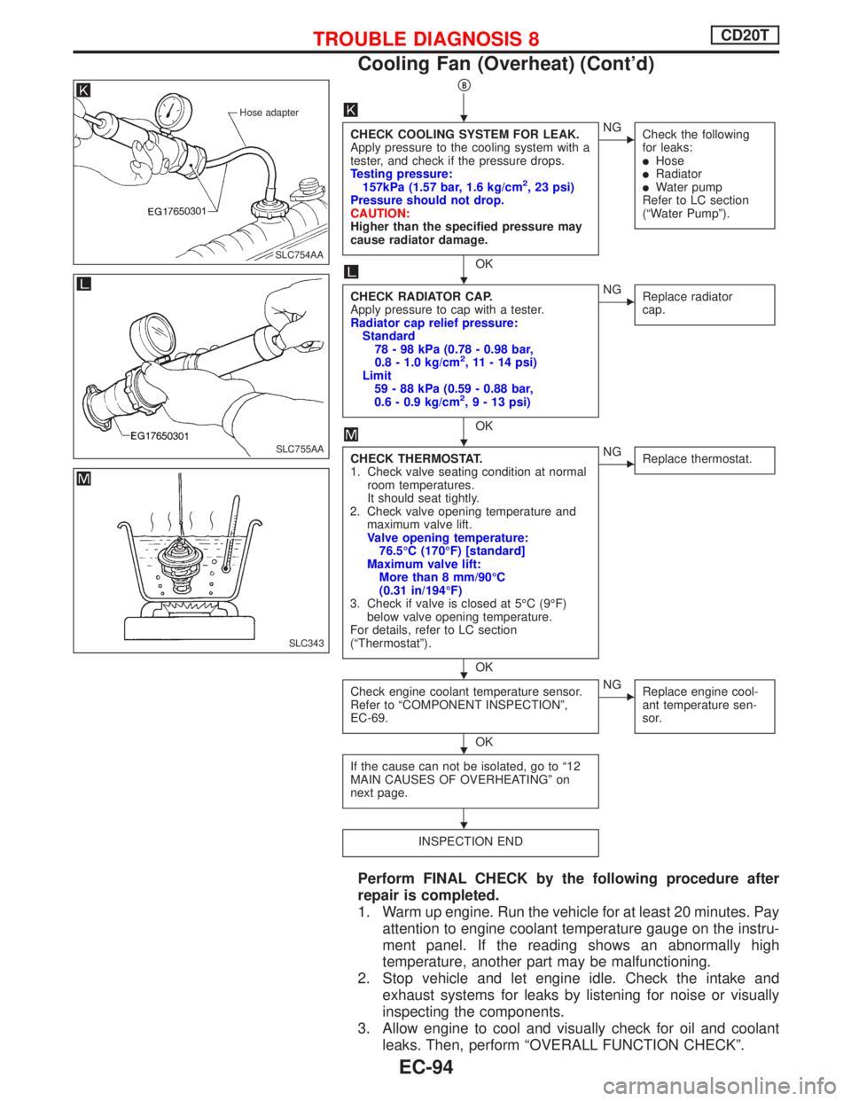
pB
CHECK COOLING SYSTEM FOR LEAK.
Apply pressure to the cooling system with a
tester, and check if the pressure drops.
Testing pressure:
157kPa (1.57 bar, 1.6 kg/cm
2, 23 psi)
Pressure should not drop.
CAUTION:
Higher than the specified pressure may
cause radiator damage.
OK
ENG
Check the following
for leaks:
lHoselRadiatorlWater pump
Refer to LC section
(ªWater Pumpº).
CHECK RADIATOR CAP.
Apply pressure to cap with a tester.
Radiator cap relief pressure:
Standard
78 - 98 kPa (0.78 - 0.98 bar,
0.8 - 1.0 kg/cm
2, 11 - 14 psi)
Limit
59 - 88 kPa (0.59 - 0.88 bar,
0.6 - 0.9 kg/cm
2,9-13psi)
OK
ENG
Replace radiator
cap.
CHECK THERMOSTAT.
1. Check valve seating condition at normal
room temperatures.
It should seat tightly.
2. Check valve opening temperature and
maximum valve lift.
Valve opening temperature:
76.5ÉC (170ÉF) [standard]
Maximum valve lift:
More than 8 mm/90ÉC
(0.31 in/194ÉF)
3. Check if valve is closed at 5ÉC (9ÉF)
below valve opening temperature.
For details, refer to LC section
(ªThermostatº).
OK
ENG
Replace thermostat.
Check engine coolant temperature sensor.
Refer to ªCOMPONENT INSPECTIONº,
EC-69.
OK
ENG
Replace engine cool-
ant temperature sen-
sor.
If the cause can not be isolated, go to ª12
MAIN CAUSES OF OVERHEATINGº on
next page.
INSPECTION END
Perform FINAL CHECK by the following procedure after
repair is completed.
1. Warm up engine. Run the vehicle for at least 20 minutes. Pay
attention to engine coolant temperature gauge on the instru-
ment panel. If the reading shows an abnormally high
temperature, another part may be malfunctioning.
2. Stop vehicle and let engine idle. Check the intake and
exhaust systems for leaks by listening for noise or visually
inspecting the components.
3. Allow engine to cool and visually check for oil and coolant
leaks. Then, perform ªOVERALL FUNCTION CHECKº.
Hose adapter
.SLC754AA
SLC755AA
SLC343
H
H
H
H
H
H
TROUBLE DIAGNOSIS 8CD20T
Cooling Fan (Overheat) (Cont'd)
EC-94
Page 389 of 2267
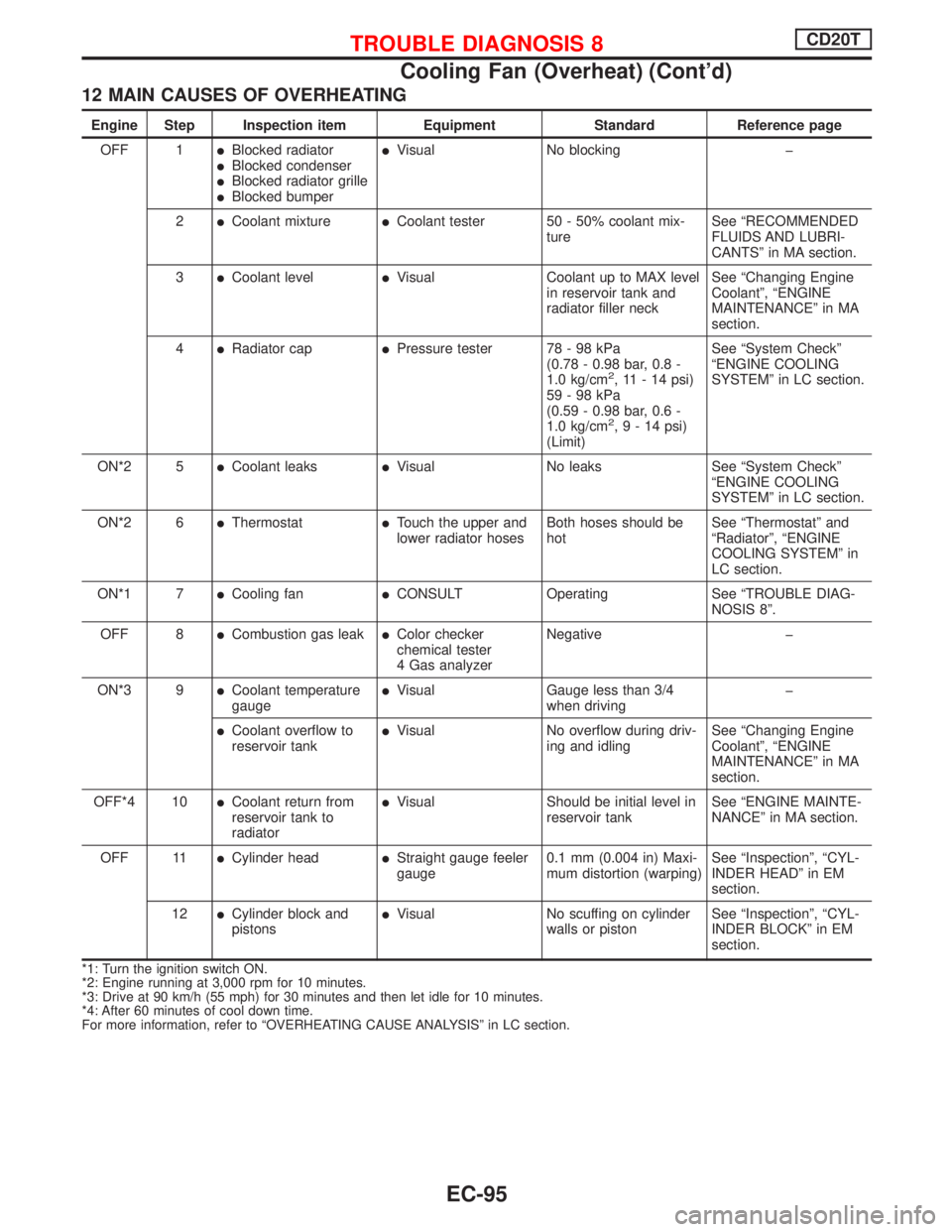
12 MAIN CAUSES OF OVERHEATING
Engine Step Inspection item Equipment Standard Reference page
OFF 1
lBlocked radiatorlBlocked condenserlBlocked radiator grillelBlocked bumper
lVisual No blocking þ
2
lCoolant mixturelCoolant tester 50 - 50% coolant mix-
tureSee ªRECOMMENDED
FLUIDS AND LUBRI-
CANTSº in MA section.
3
lCoolant levellVisual Coolant up to MAX level
in reservoir tank and
radiator filler neckSee ªChanging Engine
Coolantº, ªENGINE
MAINTENANCEº in MA
section.
4
lRadiator caplPressure tester 78 - 98 kPa
(0.78 - 0.98 bar, 0.8 -
1.0 kg/cm
2, 11 - 14 psi)
59-98kPa
(0.59 - 0.98 bar, 0.6 -
1.0 kg/cm
2,9-14psi)
(Limit)See ªSystem Checkº
ªENGINE COOLING
SYSTEMº in LC section.
ON*2 5
lCoolant leakslVisual No leaks See ªSystem Checkº
ªENGINE COOLING
SYSTEMº in LC section.
ON*2 6
lThermostatlTouch the upper and
lower radiator hosesBoth hoses should be
hotSee ªThermostatº and
ªRadiatorº, ªENGINE
COOLING SYSTEMº in
LC section.
ON*1 7
lCooling fanlCONSULT Operating See ªTROUBLE DIAG-
NOSIS 8º.
OFF 8
lCombustion gas leaklColor checker
chemical tester
4 Gas analyzerNegative þ
ON*3 9
lCoolant temperature
gaugelVisual Gauge less than 3/4
when drivingþ
lCoolant overflow to
reservoir tanklVisual No overflow during driv-
ing and idlingSee ªChanging Engine
Coolantº, ªENGINE
MAINTENANCEº in MA
section.
OFF*4 10
lCoolant return from
reservoir tank to
radiatorlVisual Should be initial level in
reservoir tankSee ªENGINE MAINTE-
NANCEº in MA section.
OFF 11
lCylinder headlStraight gauge feeler
gauge0.1 mm (0.004 in) Maxi-
mum distortion (warping)See ªInspectionº, ªCYL-
INDER HEADº in EM
section.
12
lCylinder block and
pistonslVisual No scuffing on cylinder
walls or pistonSee ªInspectionº, ªCYL-
INDER BLOCKº in EM
section.
*1: Turn the ignition switch ON.
*2: Engine running at 3,000 rpm for 10 minutes.
*3: Drive at 90 km/h (55 mph) for 30 minutes and then let idle for 10 minutes.
*4: After 60 minutes of cool down time.
For more information, refer to ªOVERHEATING CAUSE ANALYSISº in LC section.
TROUBLE DIAGNOSIS 8CD20T
Cooling Fan (Overheat) (Cont'd)
EC-95
Page 522 of 2267
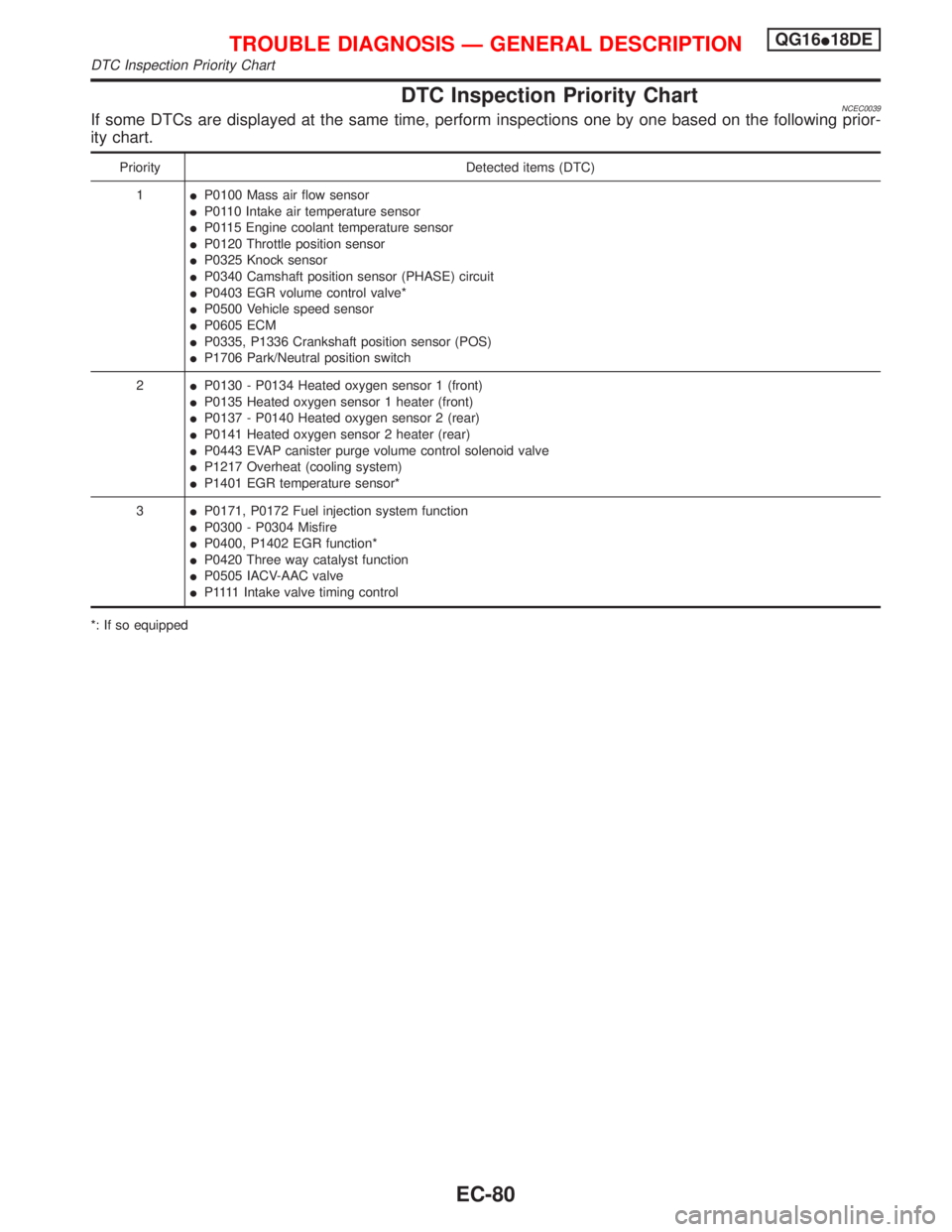
DTC Inspection Priority ChartNCEC0039If some DTCs are displayed at the same time, perform inspections one by one based on the following prior-
ity chart.
Priority Detected items (DTC)
1IP0100 Mass air flow sensor
IP0110 Intake air temperature sensor
IP0115 Engine coolant temperature sensor
IP0120 Throttle position sensor
IP0325 Knock sensor
IP0340 Camshaft position sensor (PHASE) circuit
IP0403 EGR volume control valve*
IP0500 Vehicle speed sensor
IP0605 ECM
IP0335, P1336 Crankshaft position sensor (POS)
IP1706 Park/Neutral position switch
2IP0130 - P0134 Heated oxygen sensor 1 (front)
IP0135 Heated oxygen sensor 1 heater (front)
IP0137 - P0140 Heated oxygen sensor 2 (rear)
IP0141 Heated oxygen sensor 2 heater (rear)
IP0443 EVAP canister purge volume control solenoid valve
IP1217 Overheat (cooling system)
IP1401 EGR temperature sensor*
3IP0171, P0172 Fuel injection system function
IP0300 - P0304 Misfire
IP0400, P1402 EGR function*
IP0420 Three way catalyst function
IP0505 IACV-AAC valve
IP 1111Intake valve timing control
*: If so equipped
TROUBLE DIAGNOSIS Ð GENERAL DESCRIPTIONQG16I18DE
DTC Inspection Priority Chart
EC-80
Page 524 of 2267
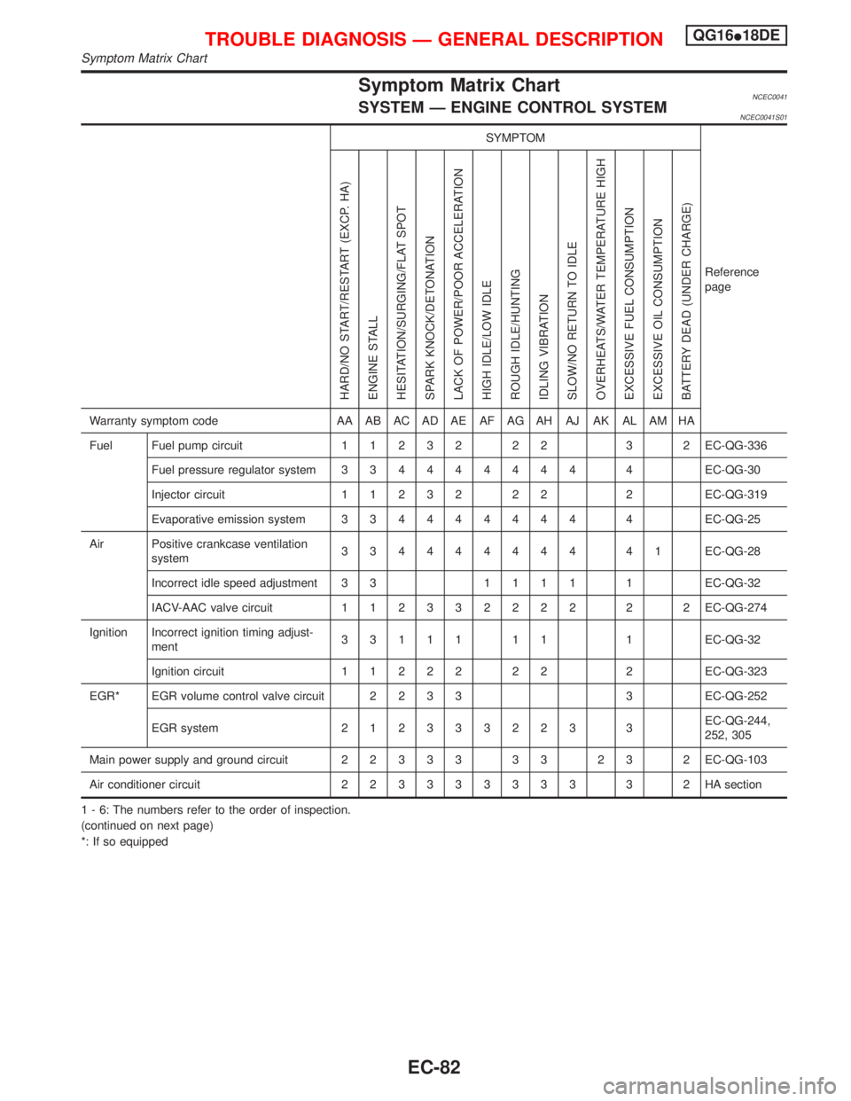
Symptom Matrix ChartNCEC0041SYSTEM Ð ENGINE CONTROL SYSTEMNCEC0041S01
SYMPTOM
Reference
page
HARD/NO START/RESTART (EXCP. HA)
ENGINE STALL
HESITATION/SURGING/FLAT SPOT
SPARK KNOCK/DETONATION
LACK OF POWER/POOR ACCELERATION
HIGH IDLE/LOW IDLE
ROUGH IDLE/HUNTING
IDLING VIBRATION
SLOW/NO RETURN TO IDLE
OVERHEATS/WATER TEMPERATURE HIGH
EXCESSIVE FUEL CONSUMPTION
EXCESSIVE OIL CONSUMPTION
BATTERY DEAD (UNDER CHARGE)
Warranty symptom code AA AB AC AD AE AF AG AH AJ AK AL AM HA
Fuel Fuel pump circuit11232 22 3 2EC-QG-336
Fuel pressure regulator system334444444 4EC-QG-30
Injector circuit11232 22 2EC-QG-319
Evaporative emission system334444444 4EC-QG-25
Air Positive crankcase ventilation
system334444444 41EC-QG-28
Incorrect idle speed adjustment 3 31111 1EC-QG-32
IACV-AAC valve circuit112332222 2 2EC-QG-274
Ignition Incorrect ignition timing adjust-
ment33111 11 1EC-QG-32
Ignition circuit11222 22 2EC-QG-323
EGR* EGR volume control valve circuit2233 3EC-QG-252
EGR system212333223 3EC-QG-244,
252, 305
Main power supply and ground circuit22333 33 23 2EC-QG-103
Air conditioner circuit223333333 3 2HAsection
1 - 6: The numbers refer to the order of inspection.
(continued on next page)
*: If so equipped
TROUBLE DIAGNOSIS Ð GENERAL DESCRIPTIONQG16I18DE
Symptom Matrix Chart
EC-82
Page 525 of 2267
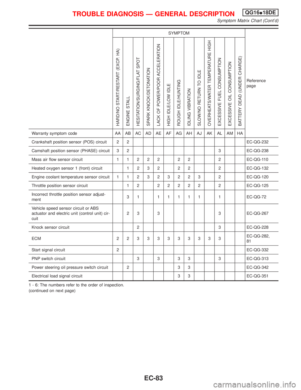
SYMPTOM
Reference
page
HARD/NO START/RESTART (EXCP. HA)
ENGINE STALL
HESITATION/SURGING/FLAT SPOT
SPARK KNOCK/DETONATION
LACK OF POWER/POOR ACCELERATION
HIGH IDLE/LOW IDLE
ROUGH IDLE/HUNTING
IDLING VIBRATION
SLOW/NO RETURN TO IDLE
OVERHEATS/WATER TEMPERATURE HIGH
EXCESSIVE FUEL CONSUMPTION
EXCESSIVE OIL CONSUMPTION
BATTERY DEAD (UNDER CHARGE)
Warranty symptom code AA AB AC AD AE AF AG AH AJ AK AL AM HA
Crankshaft position sensor (POS) circuit 2 2 EC-QG-232
Camshaft position sensor (PHASE) circuit 3 2 3 EC-QG-238
Mass air flow sensor circuit11222 22 2EC-QG-110
Heated oxygen sensor 1 (front) circuit1232 22 2EC-QG-132
Engine coolant temperature sensor circuit112323223 2EC-QG-120
Throttle position sensor circuit 1 222222 2EC-QG-125
Incorrect throttle position sensor adjust-
ment31 11111 1EC-QG-72
Vehicle speed sensor circuit or ABS
actuator and electric unit (control unit) cir-
cuit2 3 3 3 EC-QG-267
Knock sensor circuit 2 3 EC-QG-228
ECM 22333333333EC-QG-282,
81
Start signal circuit 2 EC-QG-332
PNP switch circuit 3 3 3 3 3 EC-QG-313
Power steering oil pressure switch circuit 2 3 3 EC-QG-342
Electrical load signal circuit 3 3 EC-QG-351
1 - 6: The numbers refer to the order of inspection.
(continued on next page)
TROUBLE DIAGNOSIS Ð GENERAL DESCRIPTIONQG16I18DE
Symptom Matrix Chart (Cont'd)
EC-83
Page 526 of 2267
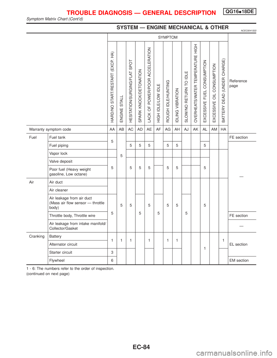
SYSTEM Ð ENGINE MECHANICAL & OTHERNCEC0041S03
SYMPTOM
Reference
page
HARD/NO START/RESTART (EXCP. HA)
ENGINE STALL
HESITATION/SURGING/FLAT SPOT
SPARK KNOCK/DETONATION
LACK OF POWER/POOR ACCELERATION
HIGH IDLE/LOW IDLE
ROUGH IDLE/HUNTING
IDLING VIBRATION
SLOW/NO RETURN TO IDLE
OVERHEATS/WATER TEMPERATURE HIGH
EXCESSIVE FUEL CONSUMPTION
EXCESSIVE OIL CONSUMPTION
BATTERY DEAD (UNDER CHARGE)
Warranty symptom code AA AB AC AD AE AF AG AH AJ AK AL AM HA
Fuel Fuel tank
5
5FE section
Fuel piping 5 5 5 5 5 5
Ð Vapor lock
Valve deposit
5 555 55 5
Poor fuel (Heavy weight
gasoline, Low octane)
Air Air duct
55555 5 Air cleaner
Air leakage from air duct
(Mass air flow sensor Ð throttle
body)
5555
Throttle body, Throttle wireFE section
Air leakage from intake manifold/
Collector/GasketÐ
Cranking Battery
111111
11
EL section Alternator circuit
Starter circuit 3
Flywheel 6 EM section
1 - 6: The numbers refer to the order of inspection.
(continued on next page)
TROUBLE DIAGNOSIS Ð GENERAL DESCRIPTIONQG16I18DE
Symptom Matrix Chart (Cont'd)
EC-84
Page 527 of 2267
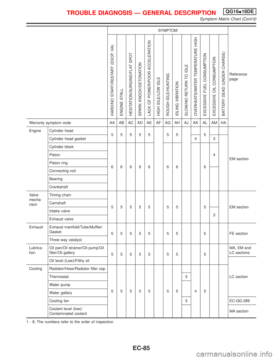
SYMPTOM
Reference
page
HARD/NO START/RESTART (EXCP. HA)
ENGINE STALL
HESITATION/SURGING/FLAT SPOT
SPARK KNOCK/DETONATION
LACK OF POWER/POOR ACCELERATION
HIGH IDLE/LOW IDLE
ROUGH IDLE/HUNTING
IDLING VIBRATION
SLOW/NO RETURN TO IDLE
OVERHEATS/WATER TEMPERATURE HIGH
EXCESSIVE FUEL CONSUMPTION
EXCESSIVE OIL CONSUMPTION
BATTERY DEAD (UNDER CHARGE)
Warranty symptom code AA AB AC AD AE AF AG AH AJ AK AL AM HA
Engine Cylinder head
55555 55 5
EM section Cylinder head gasket 4 3
Cylinder block
66666 66 64 Piston
Piston ring
Connecting rod
Bearing
Crankshaft
Valve
mecha-
nismTiming chain
55555 55 5 EMsection Camshaft
Intake valve
3
Exhaust valve
Exhaust Exhaust manifold/Tube/Muffler/
Gasket
55555 55 5 FEsection
Three way catalyst
Lubrica-
tionOil pan/Oil strainer/Oil pump/Oil
filter/Oil gallery
55555 55 5MA, EM and
LC sections
Oil level (Low)/Filthy oil
LC section Cooling Radiator/Hose/Radiator filler cap
55555 55 45 Thermostat 5
Water pump
Water gallery
Cooling fan 5 EC-QG-289
Coolant level (low)/
Contaminated coolantMA section
1 - 6: The numbers refer to the order of inspection.
TROUBLE DIAGNOSIS Ð GENERAL DESCRIPTIONQG16I18DE
Symptom Matrix Chart (Cont'd)
EC-85