1999 NISSAN PICK-UP ESP
[x] Cancel search: ESPPage 2 of 666
FOREWORD
This manual contains maintenance and repair procedures for NISSAN
PICKUP, model D22 series.
In order to assure your safety and the efficient functioning of the vehicle,
this manual should be read thoroughly. It is especially important that the
PRECAUTIONS in the GI section be completely understood before starting
any repair task.
All information in this manual is based on the latest product information
at the time of publication. The right is reserved to make changes in speci-
®cations and methods at any time without notice.
IMPORTANT SAFETY NOTICE
The proper performance of service is essential for both the safety of the
technician and the efficient functioning of the vehicle.
The service methods in this Service Manual are described in such a man-
ner that the service may be performed safely and accurately.
Service varies with the procedures used, the skills of the technician and the
tools and parts available. Accordingly, anyone using service procedures,
tools or parts which are not speci®cally recommended by NISSAN must
®rst completely satisfy himself that neither his safety nor the vehicle's
safety will be jeopardized by the service method selected.
NISSAN EUROPE S.A.S.
Service Engineering Section
Paris, France
Page 471 of 666
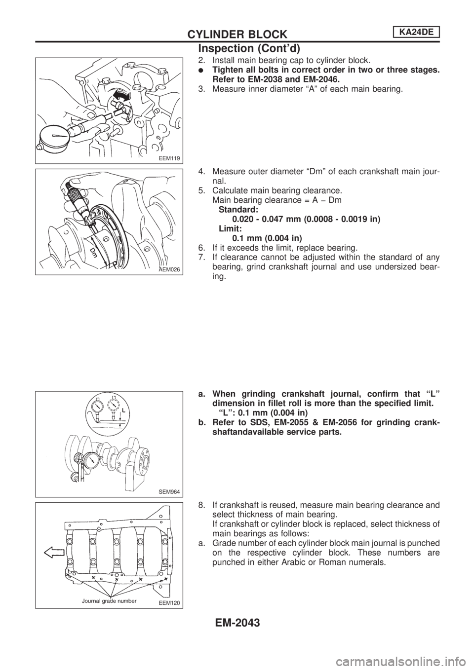
2. Install main bearing cap to cylinder block.
lTighten all bolts in correct order in two or three stages.
Refer to EM-2038 and EM-2046.
3. Measure inner diameter ªAº of each main bearing.
4. Measure outer diameter ªDmº of each crankshaft main jour-
nal.
5. Calculate main bearing clearance.
Main bearing clearance=AþDm
Standard:
0.020 - 0.047 mm (0.0008 - 0.0019 in)
Limit:
0.1 mm (0.004 in)
6. If it exceeds the limit, replace bearing.
7. If clearance cannot be adjusted within the standard of any
bearing, grind crankshaft journal and use undersized bear-
ing.
a. When grinding crankshaft journal, confirm that ªLº
dimension in fillet roll is more than the specified limit.
ªLº: 0.1 mm (0.004 in)
b. Refer to SDS, EM-2055 & EM-2056 for grinding crank-
shaftandavailable service parts.
8. If crankshaft is reused, measure main bearing clearance and
select thickness of main bearing.
If crankshaft or cylinder block is replaced, select thickness of
main bearings as follows:
a. Grade number of each cylinder block main journal is punched
on the respective cylinder block. These numbers are
punched in either Arabic or Roman numerals.
EEM119
AEM026
SEM964
EEM120
CYLINDER BLOCKKA24DE
Inspection (Cont'd)
EM-2043
Page 475 of 666
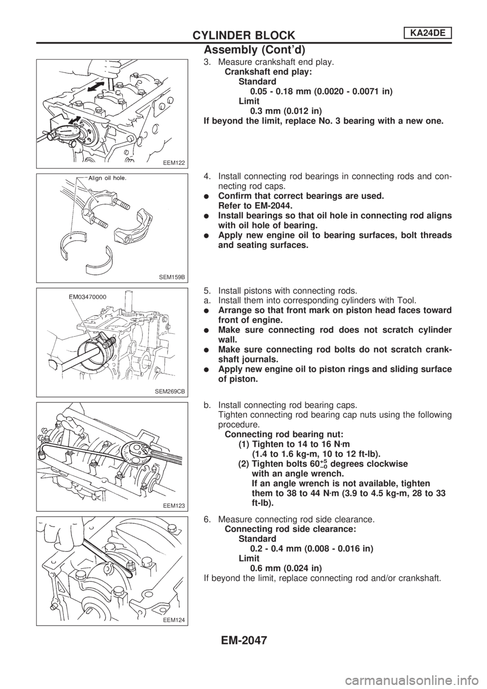
3. Measure crankshaft end play.
Crankshaft end play:
Standard
0.05 - 0.18 mm (0.0020 - 0.0071 in)
Limit
0.3 mm (0.012 in)
If beyond the limit, replace No. 3 bearing with a new one.
4. Install connecting rod bearings in connecting rods and con-
necting rod caps.
lConfirm that correct bearings are used.
Refer to EM-2044.
lInstall bearings so that oil hole in connecting rod aligns
with oil hole of bearing.
lApply new engine oil to bearing surfaces, bolt threads
and seating surfaces.
5. Install pistons with connecting rods.
a. Install them into corresponding cylinders with Tool.
lArrange so that front mark on piston head faces toward
front of engine.
lMake sure connecting rod does not scratch cylinder
wall.
lMake sure connecting rod bolts do not scratch crank-
shaft journals.
lApply new engine oil to piston rings and sliding surface
of piston.
b. Install connecting rod bearing caps.
Tighten connecting rod bearing cap nuts using the following
procedure.
Connecting rod bearing nut:
(1) Tighten to 14 to 16 Nzm
(1.4 to 1.6 kg-m, 10 to 12 ft-lb).
(2) Tighten bolts 60
+5
þ0degrees clockwise
with an angle wrench.
If an angle wrench is not available, tighten
them to 38 to 44 Nzm (3.9 to 4.5 kg-m, 28 to 33
ft-lb).
6. Measure connecting rod side clearance.
Connecting rod side clearance:
Standard
0.2 - 0.4 mm (0.008 - 0.016 in)
Limit
0.6 mm (0.024 in)
If beyond the limit, replace connecting rod and/or crankshaft.
EEM122
SEM159B
SEM269CB
EEM123
EEM124
CYLINDER BLOCKKA24DE
Assembly (Cont'd)
EM-2047
Page 536 of 666
VA
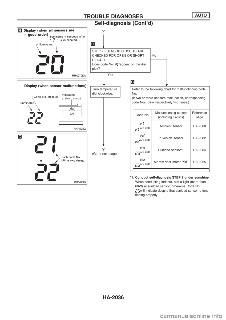
STEP 2 - SENSOR CIRCUITS ARE
CHECKED FOR OPEN OR SHORT
CIRCUIT.
Does code No.
appear on the dis-
play?
YesNo
.
Turn temperature
dial clockwise.Refer to the following chart for malfunctioning code
No.
(If two or more sensors malfunction, corresponding
code Nos. blink respectively two times.)
*1: Conduct self-diagnosis STEP 2 under sunshine.
When conducting indoors, aim a light (more than
60W) at sunload sensor, otherwise Code No.
will indicate despite that sunload sensor is func-
tioning properly.
VB
(Go to next page.)
Code No.Malfunctioning sensor
(including circuits)Reference
page
Ambient sensor HA-2080A/C LED
In-vehicle sensor HA-2082A/C LED
Sunload sensor*1 HA-2084A/C LED
Air mix door motor PBR HA-2055A/C LED
RHA970DA
RHA528G
RHA501A
.
.
.
TROUBLE DIAGNOSESAUTO
Self-diagnosis (Cont'd)
HA-2036
Page 537 of 666
VB
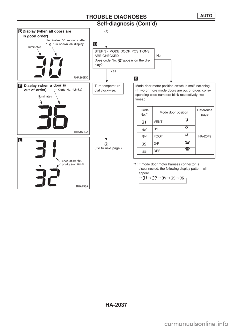
STEP 3 - MODE DOOR POSITIONS
ARE CHECKED.
Does code No.
appear on the dis-
play?
YesNo
.
Turn temperature
dial clockwise.Mode door motor position switch is malfunctioning.
(If two or more mode doors are out of order, corre-
sponding code numbers blink respectively two
times.)
*1: If mode door motor harness connector is
disconnected, the following display pattern will
appear.
®
®®®®þ
VC
(Go to next page.)
Code
No.*1Mode door positionReference
page
VENT
HA-2049
B/L
FOOT
D/F
DEF
RHA869DC
RHA168DA
RHA498A
.
.
.
TROUBLE DIAGNOSESAUTO
Self-diagnosis (Cont'd)
HA-2037
Page 649 of 666
![NISSAN PICK-UP 1999 Repair Manual If no malfunction is detected on ``SELF-DIAG [CURRENT] even
though malfunction is detected by the ``AIR BAG warning lamp,
check the battery voltage.
If the battery voltage is less than 9V, charge NISSAN PICK-UP 1999 Repair Manual If no malfunction is detected on ``SELF-DIAG [CURRENT] even
though malfunction is detected by the ``AIR BAG warning lamp,
check the battery voltage.
If the battery voltage is less than 9V, charge](/manual-img/5/57373/w960_57373-648.png)
If no malfunction is detected on ``SELF-DIAG [CURRENT]'' even
though malfunction is detected by the ``AIR BAG'' warning lamp,
check the battery voltage.
If the battery voltage is less than 9V, charge the battery. Then
go to DIAGNOSTIC PROCEDURE 4 for final checking, page
RS-2030.
If the battery voltage is OK, go to DIAGNOSTIC PROCEDURE
6, page RS-2034, to diagnose the following situations:
lSelf-diagnostic result (previously stored in the memory)
might not be erased after repair.
lThe SRS system malfunctions intermittently.
8. Touch ``PRINT''.
9. Compare diagnostic codes to the CONSULT DIAGNOSTIC
CODE CHART, page RS-2028.
10. Touch ``BACK'' key of CONSULT until ``SELECT SYSTEM''
appears in order to return to User mode from Diagnosis
mode, then turn off CONSULT.
11. Turn ignition switch ``OFF'', then disconnect CONSULT and
both battery cables.
12. Repair the system as outlined by the ``Repair order'' in CON-
SULT DIAGNOSTIC CODE CHART, that corresponds to the
self-diagnostic result. For replacement procedure of compo-
nent parts, refer to RS-2007.
13. After repairing the system, go to DIAGNOSTIC PROCE-
DURE 4 for final checking, page RS-2030.SRS049
TROUBLE DIAGNOSES Ð Supplemental Restraint System (SRS)
Self-diagnosis (Cont'd)
RS-2027
Page 658 of 666
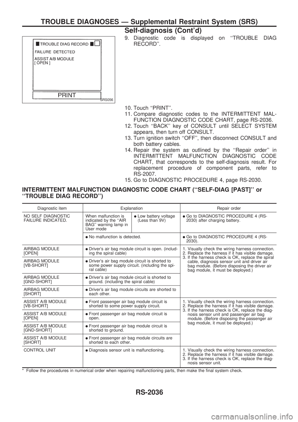
9. Diagnostic code is displayed on ``TROUBLE DIAG
RECORD''.
10. Touch ``PRINT''.
11. Compare diagnostic codes to the INTERMITTENT MAL-
FUNCTION DIAGNOSTIC CODE CHART, page RS-2036.
12. Touch ``BACK'' key of CONSULT until SELECT SYSTEM
appears, then turn off CONSULT.
13. Turn ignition switch ``OFF'', then disconnect CONSULT and
both battery cables.
14. Repair the system as outlined by the ``Repair order'' in
INTERMITTENT MALFUNCTION DIAGNOSTIC CODE
CHART, that corresponds to the self-diagnosis result. For
replacement procedure of component parts, refer to
RS-2007.
15. Go to DIAGNOSTIC PROCEDURE 4, page RS-2030.
INTERMITTENT MALFUNCTION DIAGNOSTIC CODE CHART (``SELF-DIAG [PAST]'' or
``TROUBLE DIAG RECORD'')
Diagnostic item Explanation Repair order
NO SELF DIAGNOSTIC
FAILURE INDICATED.When malfunction is
indicated by the ``AIR
BAG'' warning lamp in
User mode
lLow battery voltage
(Less than 9V)lGo to DIAGNOSTIC PROCEDURE 4 (RS-
2030) after charging battery.
lNo malfunction is detected.lGo to DIAGNOSTIC PROCEDURE 4 (RS-
2030).
AIRBAG MODULE
[OPEN]
lDriver's air bag module circuit is open. (includ-
ing the spiral cable)1. Visually check the wiring harness connection.
2. Replace the harness if it has visible damage.
3. If the harness check is OK, replace the spiral
cable, diagnosis sensor unit and driver air
bag module. (Before disposing the driver air
bag module, it must be deployed.) AIRBAG MODULE
[VB-SHORT]
lDriver's air bag module circuit is shorted to
some power supply circuit. (including the spi-
ral cable)
AIRBAG MODULE
[GND-SHORT]
lDriver's air bag module circuit is shorted to
ground. (including the spiral cable)
AIRBAG MODULE
[SHORT]
lDriver's air bag module circuits are shorted to
each other.
ASSIST A/B MODULE
[VB-SHORT]
lFront passenger air bag module circuit is
shorted to some power supply circuit.1. Visually check the wiring harness connection.
2. Replace the harness if it has visible damage.
3. If the harness check is OK, replace the diag-
nosis sensor unit and passenger air bag
module. (Before disposing the passenger air
bag module, it must be deployed.) ASSIST A/B MODULE
[OPEN]
lFront passenger air bag module circuit is
open.
ASSIST A/B MODULE
[GND-SHORT]
lFront passenger air bag module circuit is
shorted to ground.
ASSIST A/B MODULE
[SHORT]
lFront passenger air bag module circuits are
shorted to each other.
CONTROL UNIT
lDiagnosis sensor unit is malfunctioning. 1. Visually check the wiring harness connection.
2. Replace the harness if it has visible damage.
3. If the harness check is OK, replace the diag-
nosis sensor unit.
* Follow the procedures in numerical order when repairing malfunctioning parts, then make the final system check.
SRS056
TROUBLE DIAGNOSES Ð Supplemental Restraint System (SRS)
Self-diagnosis (Cont'd)
RS-2036