Page 26 of 558

11-1
ENGINE
CONTENTS
GENERAL INFORMATION 2. . . . . . . . . . . . . . . .
SPECIFICATIONS 3. . . . . . . . . . . . . . . . . . . . . . . .
Service Specifications 3. . . . . . . . . . . . . . . . . . . . . .
Torque Specifications 5. . . . . . . . . . . . . . . . . . . . . .
New Tightening Method by Use of Bolts
to Be Tightened in Plastic Area 9. . . . . . . . . . . .
Sealants 9. . . . . . . . . . . . . . . . . . . . . . . . . . . . . . . . . .
Form-In-Place Gasket 10. . . . . . . . . . . . . . . . . . . .
SPECIAL TOOLS 11. . . . . . . . . . . . . . . . . . . . . . .
ALTERNATOR AND IGNITION SYSTEM 14.
TIMING BELT 15. . . . . . . . . . . . . . . . . . . . . . . . .
FUEL AND EMISSION CONTROL PARTS 27
SECONDARY AIR SYSTEM AND INTAKE
MANIFOLD 29. . . . . . . . . . . . . . . . . . . . . . . . . . . . EXHAUST MANIFOLD 31. . . . . . . . . . . . . . . . .
WATER PUMP AND WATER HOSE 34. . . . .
ROCKER ARMS AND CAMSHAFT 37. . . . . .
CYLINDER HEAD AND VALVES 43. . . . . . . .
FRONT CASE, COUNTERBALANCE
SHAFT AND OIL PAN 51. . . . . . . . . . . . . . . . .
PISTON AND CONNECTING ROD 59. . . . . .
CRANKSHAFT AND FLYWHEEL 67. . . . . . . .
THROTTLE BODY 73. . . . . . . . . . . . . . . . . . . . .
TURBOCHARGER 75. . . . . . . . . . . . . . . . . . . . .
ALTERNATOR 79. . . . . . . . . . . . . . . . . . . . . . . . .
STARTER MOTOR 83. . . . . . . . . . . . . . . . . . . . .
Page 96 of 558

ENGINE – Crankshaft and Flywheel11-71
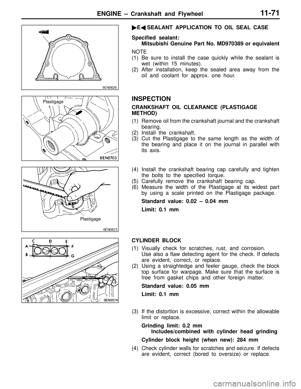
�E�SEALANT APPLICATION TO OIL SEAL CASE
Specified sealant:
Mitsubishi Genuine Part No. MD970389 or equivalent
NOTE
(1) Be sure to install the case quickly while the sealant is
wet (within 15 minutes).
(2) After installation, keep the sealed area away from the
oil and coolant for approx. one hour.
INSPECTION
CRANKSHAFT OIL CLEARANCE (PLASTIGAGE
METHOD)
(1) Remove oil from the crankshaft journal and the crankshaft
bearing.
(2) Install the crankshaft.
(3) Cut the Plastigage to the same length as the width of
the bearing and place it on the journal in parallel with
its axis.
(4) Install the crankshaft bearing cap carefully and tighten
the bolts to the specified torque.
(5) Carefully remove the crankshaft bearing cap.
(6) Measure the width of the Plastigage at its widest part
by using a scale printed on the Plastigage package.
Standard value: 0.02 – 0.04 mm
Limit: 0.1 mm
CYLINDER BLOCK
(1) Visually check for scratches, rust, and corrosion.
Use also a flaw detecting agent for the check. If defects
are evident, correct, or replace.
(2) Using a straightedge and feeler gauge, check the block
top surface for warpage. Make sure that the surface is
free from gasket chips and other foreign matter.
Standard value: 0.05 mm
Limit: 0.1 mm
(3) If the distortion is excessive, correct within the allowable
limit or replace.
Grinding limit: 0.2 mm
Includes/combined with cylinder head grinding
Cylinder block height (when new): 284 mm
(4) Check cylinder walls for scratches and seizure. If defects
are evident, correct (bored to oversize) or replace.
Plastigage
Plastigage
Page 239 of 558
FRONT SUSPENSION – General / Lower Arm 33A-1
GROUP 33A
FRONT SUSPENSION
GENERAL
OUTLINE OF CHANGE
�The installation method of the ball joint between the knuckle and the lower arm has been changed,
and accordingly the removal and installation procedures of the lower arm have been revised.
LOWER ARM
REMOVAL AND INSTALLATION
Caution
The part marked with * should be first temporarily tightened, then torqued to specification with the vehicle
on the ground in unloaded condition.
Post-installation Operation
�Push the Dust Cover of the Lower Arm and Stabilizer Link Ball Joint with a Finger to Check for Possible Cracks or Damage.
�Wheel Alignment Check and Adjustment
1
2
3
4
5
6
39 Nm
106 Nm*
5
98 – 118 Nm
74 – 87 Nm88 Nm
137 Nm
Removal steps
1. Stabilizer link mounting nut
2. Bolt
3. Stabilizer bracket
�A�4. Bushing assembly
5. Lower arm assembly6. Lower arm bracket assembly
NOTE
Follow the conventional procedures for installation service
points.