Page 99 of 558

ENGINE – Throttle Body11-74
DISASSEMBLY SERVICE POINTS
�A�THROTTLE POSITION SENSOR AND IDLE AIR
CONTROL MOTOR REMOVAL
(1) Do not disassemble the sensor and motor.
(2) Do not immerse solvent to clean the sensor and motor.
Clean then with shop towel.
�B�THROTTLE BODY REMOVAL
(1) Do not remove the throttle body.
(2) Check if the vacuum port or passage is clogged. Use
compressed air to clean the vacuum passage.
REASSEMBLY SERVICE POINT
�A�THROTTLE POSITION SENSOR INSTALLATION
(1) Install the throttle position sensor to the throttle body
as shown in the diagram.
(2) Turn throttle position sensor 90° clockwise to set it, and
tighten screws.
(3) Check the continuity between terminal No. 3 (Idle throttle
position switch) and No. 4 (Earth).
Throttle valve conditionContinuity
Fully closedConductive
Fully openNo conductive
If there is no continuity with the throttle valve fully closed,
turn the throttle position sensor counterclockwise, and
then check again.
Throttle position sensor
Earth TPS power supply
TPS outputIdle position switch
Page 100 of 558
ENGINE – Turbocharger11-75
TURBOCHARGER
DISASSEMBLY AND REASSEMBLY
1 2 3
4567
8
11 Nm
Disassembly steps
�F��Inspection of turbocharger waste gate
actuator operation
1. Snap pin
2. Waste gate actuator
�E�3. Coupling�D�4. Turbine housing
�A��C�5. Snap ring
�B��B�6. Turbine wheel assembly
7. Compressor cover
�A�8. O-ring
Page 101 of 558

ENGINE – Turbocharger11-76
DISASSEMBLY SERVICE POINTS
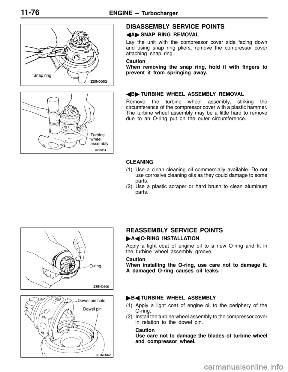
�A�SNAP RING REMOVAL
Lay the unit with the compressor cover side facing down
and using snap ring pliers, remove the compressor cover
attaching snap ring.
Caution
When removing the snap ring, hold it with fingers to
prevent it from springing away.
�B�TURBINE WHEEL ASSEMBLY REMOVAL
Remove the turbine wheel assembly, striking the
circumference of the compressor cover with a plastic hammer.
The turbine wheel assembly may be a little hard to remove
due to an O-ring put on the outer circumference.
CLEANING
(1) Use a clean cleaning oil commercially available. Do not
use corrosive cleaning oils as they could damage to some
parts.
(2) Use a plastic scraper or hard brush to clean aluminum
parts.
REASSEMBLY SERVICE POINTS
�A�O-RING INSTALLATION
Apply a light coat of engine oil to a new O-ring and fit in
the turbine wheel assembly groove.
Caution
When installing the O-ring, use care not to damage it.
A damaged O-ring causes oil leaks.
�B�TURBINE WHEEL ASSEMBLY
(1) Apply a light coat of engine oil to the periphery of the
O-ring.
(2) Install the turbine wheel assembly to the compressor cover
in relation to the dowel pin.
Caution
Use care not to damage the blades of turbine wheel
and compressor wheel.
Snap ring
Turbine
wheel
assembly
O-ring
Dowel pin hole
Dowel pin
Page 102 of 558

ENGINE – Turbocharger11-77
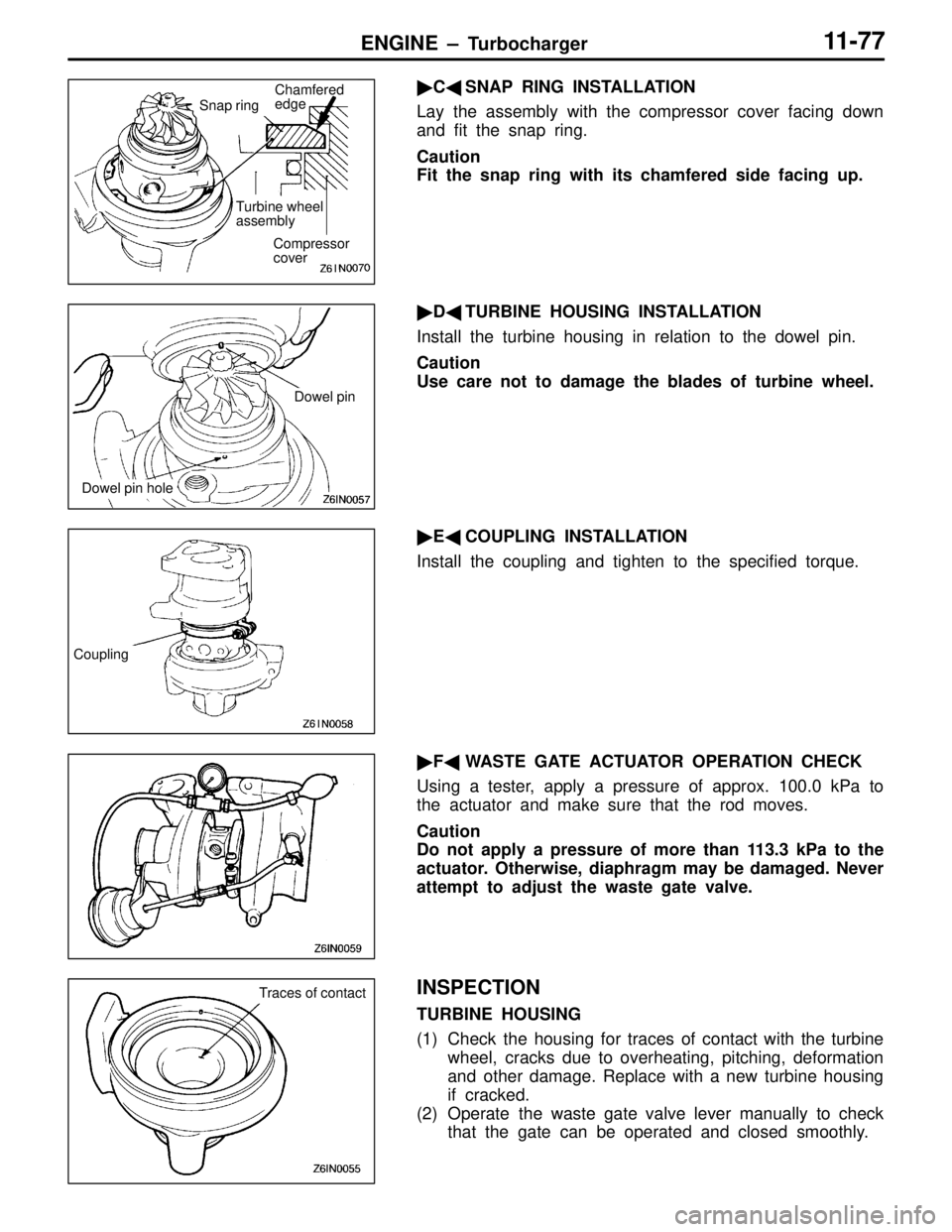
�C�SNAP RING INSTALLATION
Lay the assembly with the compressor cover facing down
and fit the snap ring.
Caution
Fit the snap ring with its chamfered side facing up.
�D�TURBINE HOUSING INSTALLATION
Install the turbine housing in relation to the dowel pin.
Caution
Use care not to damage the blades of turbine wheel.
�E�COUPLING INSTALLATION
Install the coupling and tighten to the specified torque.
�F�WASTE GATE ACTUATOR OPERATION CHECK
Using a tester, apply a pressure of approx. 100.0 kPa to
the actuator and make sure that the rod moves.
Caution
Do not apply a pressure of more than 113.3 kPa to the
actuator. Otherwise, diaphragm may be damaged. Never
attempt to adjust the waste gate valve.
INSPECTION
TURBINE HOUSING
(1) Check the housing for traces of contact with the turbine
wheel, cracks due to overheating, pitching, deformation
and other damage. Replace with a new turbine housing
if cracked.
(2) Operate the waste gate valve lever manually to check
that the gate can be operated and closed smoothly.
Compressor
cover
Turbine wheel
assembly
Chamfered
edge
Snap ring
Dowel pin
Dowel pin hole
Coupling
Traces of contact
Page 103 of 558
ENGINE – Turbocharger11-78
COMPRESSOR COVER
Check the compressor cover for traces of contact with the
compressor wheel and other damage.
TURBINE WHEEL ASSEMBLY
(1) Check the turbine and compressor wheel blades for bend,
burr, damage, corrosion and traces of contact on the
back side and replace if defective.
(2) Check the oil passage of the turbine wheel assembly
for deposit and clogging.
(3) In the case of water cooled type, check also the water
passage for deposit and clogging.
(4) Check the turbine wheel and compressor wheel for light
and smooth turning.Oil passage
Turbine wheel
Compressor
wheelWater passage
Page 104 of 558
ENGINE – Alternator11-79
ALTERNATOR
DISASSEMBLY AND REASSEMBLY
1
234
5
6
7
8910
11 12
1314
Disassembly steps
�A�1. Front bracket assembly
�B�2. Alternator pulley
�B�3. Rotor
4. Rear bearing
5. Bearing retainer
6. Front bearing
7. Front bracket�C�8. Stator
9. Plate
�C��A�10. Regulator assembly
11. Brush
12. Slinger
13. Rectifier
14. Rear bracket
Page 105 of 558

ENGINE – Alternator11-80
DISASSEMBLY SERVICE POINTS
�A�FRONT BRACKET ASSEMBLY REMOVAL
Insert a flat tip screwdrivers or the like in the clearance between
the front bracket assembly and stator core, to pry open and
separate the stator and front bracket.
Caution
Do not insert the screwdriver too far, or the stator coil
gets damaged.
�B�ALTERNATOR PULLEY REMOVAL
Face pulley side upward, fix the rotor with a work bench
and remove the pulley.
Caution
Use care not to damage the rotor.
�C�STATOR / REGULATOR ASSEMBLY REMOVAL
(1) Unsolder the stator with a soldering iron (180 to 250
W). Complete this work within four seconds not to transfer
heat to the diode.
(2) When removing rectifier from the regulator assembly,
remove the soldered sections to rectifier.
Caution
1. Use care to make sure that the heat of the soldering
iron is not transmitted to the diodes for a long
period.
2. Use care that no undue force is exerted to the
lead wires of the diodes.
REASSEMBLY SERVICE POINTS
�A�REGULATOR ASSEMBLY INSTALLATION
After installing the regulator assembly, insert a wire into the
hole provided on the rear bracket while pressing in the brush
to fix the brush.
NOTE
The brush is fixed when a wire is inserted, making rotor
installation easier.
Soldered
Rear bracket
Brush
WireWire
Page 106 of 558
ENGINE – Alternator11-81
�B�ROTOR INSTALLATION
After installing the rotor, remove the wire used to fix the brush.
INSPECTION
ROTOR CHECK
(1) Check the continuity between the rotor coil slip rings,
and replace the rotor if the resistance value is not at
the standard value.
Standard value: 3 – 5 Ω
(2) Check the continuity between the slip ring and core, and
if there is continuity, replace the rotor.
STATOR CHECK
(1) Check the continuity between the coil leads, and if there
is continuity, replace the stator.
(2) Check the continuity between the coil and core, and if
there is continuity, replace the stator.
Wire