Page 26 of 558

11-1
ENGINE
CONTENTS
GENERAL INFORMATION 2. . . . . . . . . . . . . . . .
SPECIFICATIONS 3. . . . . . . . . . . . . . . . . . . . . . . .
Service Specifications 3. . . . . . . . . . . . . . . . . . . . . .
Torque Specifications 5. . . . . . . . . . . . . . . . . . . . . .
New Tightening Method by Use of Bolts
to Be Tightened in Plastic Area 9. . . . . . . . . . . .
Sealants 9. . . . . . . . . . . . . . . . . . . . . . . . . . . . . . . . . .
Form-In-Place Gasket 10. . . . . . . . . . . . . . . . . . . .
SPECIAL TOOLS 11. . . . . . . . . . . . . . . . . . . . . . .
ALTERNATOR AND IGNITION SYSTEM 14.
TIMING BELT 15. . . . . . . . . . . . . . . . . . . . . . . . .
FUEL AND EMISSION CONTROL PARTS 27
SECONDARY AIR SYSTEM AND INTAKE
MANIFOLD 29. . . . . . . . . . . . . . . . . . . . . . . . . . . . EXHAUST MANIFOLD 31. . . . . . . . . . . . . . . . .
WATER PUMP AND WATER HOSE 34. . . . .
ROCKER ARMS AND CAMSHAFT 37. . . . . .
CYLINDER HEAD AND VALVES 43. . . . . . . .
FRONT CASE, COUNTERBALANCE
SHAFT AND OIL PAN 51. . . . . . . . . . . . . . . . .
PISTON AND CONNECTING ROD 59. . . . . .
CRANKSHAFT AND FLYWHEEL 67. . . . . . . .
THROTTLE BODY 73. . . . . . . . . . . . . . . . . . . . .
TURBOCHARGER 75. . . . . . . . . . . . . . . . . . . . .
ALTERNATOR 79. . . . . . . . . . . . . . . . . . . . . . . . .
STARTER MOTOR 83. . . . . . . . . . . . . . . . . . . . .
Page 30 of 558
ENGINE – Specifications11-5
ItemsLimit Standard value
Alternator
Rotor coil resistance ΩApprox. 3 – 5–
Protrusion length of brush mm–2
Starter motor
Commutator runout mm0.050.1
Commutator outer diameter mm32.031.4
Commutator undercut mm0.5–
TORQUE SPECIFICATIONS
ItemsNm
Alternator and ignition system
Oil level gauge guide13
Water pump pulley9
Alternator brace (Alternator side)21
Alternator brace (Tightened with water pump)23
Alternator pivot bolt44
Crankshaft pulley25
Center cover3
Spark plug25
Ignition coil10
Timing belt
Timing belt cover (Flange bolt)11
Timing belt cover (Washer bolt)9
Power steering pump bracket49
Tensioner pulley49
Tensioner arm24
Auto tensioner24
Idler pulley48
Crank angle sensor9
Oil pump sprocket54
Camshaft bolt11 8
Tensioner “B”19
Counterbalance shaft sprocket45
Page 39 of 558
ENGINE – Alternator and Ignition System11-14
ALTERNATOR AND IGNITION SYSTEM
REMOVAL AND INSTALLATION
44 Nm 10 Nm
25 Nm
21 Nm
9 Nm 13 Nm
23 Nm
25 Nm 3 Nm
2
1
34
5 67
89
10
11
12
13 1415
16
Removal steps
1. Oil level gauge
2. O-ring
3. Oil level gauge guide
4. O-ring
5. Water pump pulley
6. Alternator brace
7. Alternator
8. Crankshaft pulley9. Center cover
10. Spark plug cable
11. Ignition coil
12. Spark plug
13. Breather hose
14. PCV hose
15. PCV valve
16. PCV valve gasket
Page 54 of 558
ENGINE – Secondary Air System and Intake Manifold11-29
SECONDARY AIR SYSTEM AND INTAKE MANIFOLD
REMOVAL AND INSTALLATION
1 23 4 5
6
7
8 910
11
11 N m
35 Nm 24 Nm
11 N m
19 Nm
30 Nm 35 Nm 24 Nm
49 Nm 21 Nm
13 Nm
21 Nm
35 Nm
Removal steps
1. Exhaust manifold heat protector
2. Vacuum hose and vacuum pipe
�B�3. Air pipe assembly
4. Air control valve gasket
5. Air control valve assembly
6. Engine hanger�A�7. Air control valve bracket
8. Intake manifold stay
9. Alternator brace stay
10. Intake manifold
11. Intake manifold gasket
Page 104 of 558
ENGINE – Alternator11-79
ALTERNATOR
DISASSEMBLY AND REASSEMBLY
1
234
5
6
7
8910
11 12
1314
Disassembly steps
�A�1. Front bracket assembly
�B�2. Alternator pulley
�B�3. Rotor
4. Rear bearing
5. Bearing retainer
6. Front bearing
7. Front bracket�C�8. Stator
9. Plate
�C��A�10. Regulator assembly
11. Brush
12. Slinger
13. Rectifier
14. Rear bracket
Page 105 of 558

ENGINE – Alternator11-80
DISASSEMBLY SERVICE POINTS
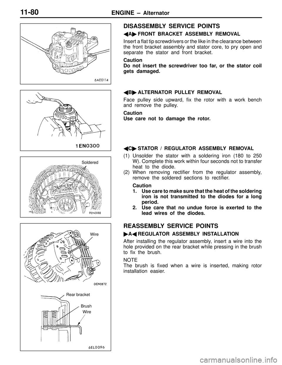
�A�FRONT BRACKET ASSEMBLY REMOVAL
Insert a flat tip screwdrivers or the like in the clearance between
the front bracket assembly and stator core, to pry open and
separate the stator and front bracket.
Caution
Do not insert the screwdriver too far, or the stator coil
gets damaged.
�B�ALTERNATOR PULLEY REMOVAL
Face pulley side upward, fix the rotor with a work bench
and remove the pulley.
Caution
Use care not to damage the rotor.
�C�STATOR / REGULATOR ASSEMBLY REMOVAL
(1) Unsolder the stator with a soldering iron (180 to 250
W). Complete this work within four seconds not to transfer
heat to the diode.
(2) When removing rectifier from the regulator assembly,
remove the soldered sections to rectifier.
Caution
1. Use care to make sure that the heat of the soldering
iron is not transmitted to the diodes for a long
period.
2. Use care that no undue force is exerted to the
lead wires of the diodes.
REASSEMBLY SERVICE POINTS
�A�REGULATOR ASSEMBLY INSTALLATION
After installing the regulator assembly, insert a wire into the
hole provided on the rear bracket while pressing in the brush
to fix the brush.
NOTE
The brush is fixed when a wire is inserted, making rotor
installation easier.
Soldered
Rear bracket
Brush
WireWire
Page 106 of 558
ENGINE – Alternator11-81
�B�ROTOR INSTALLATION
After installing the rotor, remove the wire used to fix the brush.
INSPECTION
ROTOR CHECK
(1) Check the continuity between the rotor coil slip rings,
and replace the rotor if the resistance value is not at
the standard value.
Standard value: 3 – 5 Ω
(2) Check the continuity between the slip ring and core, and
if there is continuity, replace the rotor.
STATOR CHECK
(1) Check the continuity between the coil leads, and if there
is continuity, replace the stator.
(2) Check the continuity between the coil and core, and if
there is continuity, replace the stator.
Wire
Page 107 of 558

ENGINE – Alternator11-82
RECTIFIERS CHECK
(1) Inspect the (+) heat sink by checking the continuity
between the (+) heat sink and stator coil lead wire
connection terminal using a tester probe.
If there is a continuity at both, the diode is short circuited,
so replace the rectifier.
(2) Inspect the (–) heat sink by checking the continuity
between the (–) heat sink and stator coil lead wire
connection terminal using a tester probe.
If there is a continuity at both, the diode is short circuited,
so replace the rectifier.
(3) Check the diode trio by connecting an ohmmeter to both
ends of each diode and check the continuity of the three
diodes.
If there is a continuity at both ends, or if there is no
continuity, the diode is damaged so replace the recitifier.
BRUSH CHECK
(1) Measure the length of the brush protrusion shown in the
illustration, and replace the brush if the measured value
is below the limit value.
Limit: 2 mm or less
(2) The brush can be removed if the solder of the brush
lead wire is removed.
(3) When installing a new brush, insert the brush into the
holder as shown in the illustration, and then solder the
lead wires.
Protrusion
length
Soldered