Page 29 of 558

ENGINE – Specifications11-4
ItemsLimit Standard value
Intake oversize rework dimensions of valve
guide hole mm
0.3 O.S.35.30 – 35.33–
guide hole mm0.6 O.S.35.60 – 35.63–
Exhaust oversize rework dimensions of
valve guide hole mm
0.3 O.S.33.30 – 33.33–
valve guide hole mm0.6 O.S.33.60 – 33.63–
Front case and oil pan
Oil pump side clearance mmDrive gear0.08 – 0.14–
Driven gear0.06 – 0.12–
Oil pressure at curb idle speed kPa [Oil temperature is 75 to 90°C]78 or more–
Piston and connecting rod
Piston outer diameter mm85.0–
Piston ring side clearance mmNo. 1 ring0.04 – 0.075–
No. 2 ring0.02 – 0.06–
Piston ring end gap mmNo. 1 ring0.25 – 0.350.8
No. 2 ring0.40 – 0.550.8
Oil ring0.10 – 0.401.0
Piston pin outer diameter mm21.0–
Piston pin press-in load N (Room temperature)7,350 – 17,200–
Crankshaft pin oil clearance mm0.02 – 0.050.1
Connecting rod big end side clearance mm0.10 – 0.250.4
Crankshaft and flywheel
Crankshaft end play mm0.05 – 0.250.40
Crankshaft journal outer diameter mm57.0–
Crankshaft pin outer diameter mm44.0–
Crankshaft journal oil clearance mm0.02 – 0.040.1
Bearing cap bolt shank length mm–Maximum 71.1
Piston to cylinder clearance mm0.02 – 0.04–
Cylinder block grinding limit of gasket surface mm
Total resurfacing depth of both cylinder head and cylinder block–0.2
Cylinder block overall height mm284–
Cylinder block inner diameter mm85.0–
Cylinder block cylinder mm0.01–
Turbocharger
Waste gate actuator operation check kPa100113.3
Page 93 of 558
ENGINE – Crankshaft and Flywheel11-68
INSTALLATION SERVICE POINTS
�A�CRANKSHAFT THRUST BEARING INSTALLATION
(1) Install the two thrust bearing in the number 3 bearing
bore in the cylinder block. For easier installation, apply
engine oil to the bearings; this will help hold them in
position.
(2) The thrust bearings must be installed with their groove
side toward the crankshaft web.
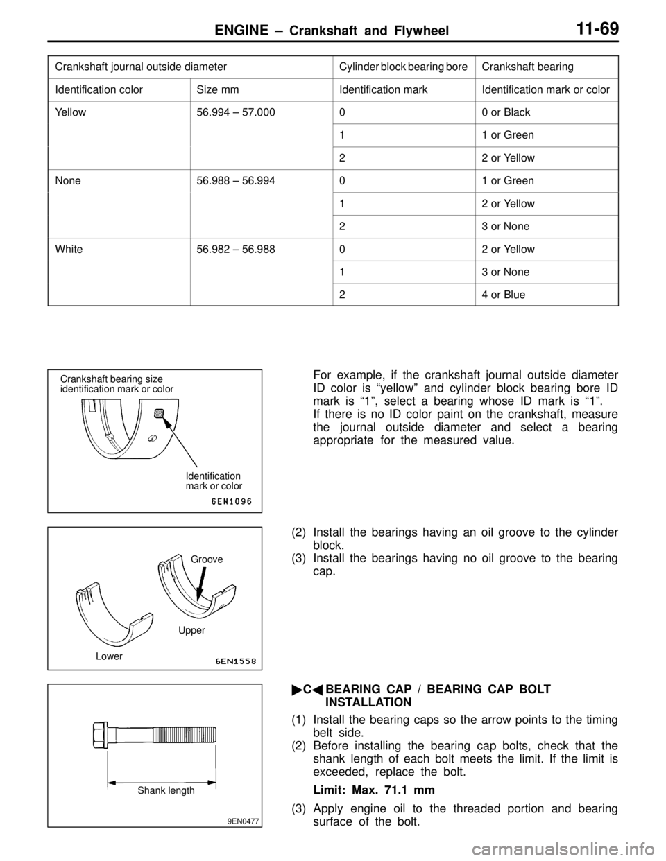
�B�CRANKSHAFT BEARING INSTALLATION
(1) From the following table, select a bearing whose size
is appropriate for the crankshaft journal outside diameter.
Groove
Identification color of crankshaft journal
Bearing bore size
identification mark
Bearing bore
identification
mark
Cylinder inner
diameter size
mark
Rear face of
cylinder block Bottom of
cylinder block No. 1 No. 2No. 3
No. 4No. 5
Page 94 of 558

ENGINE – Crankshaft and Flywheel11-69
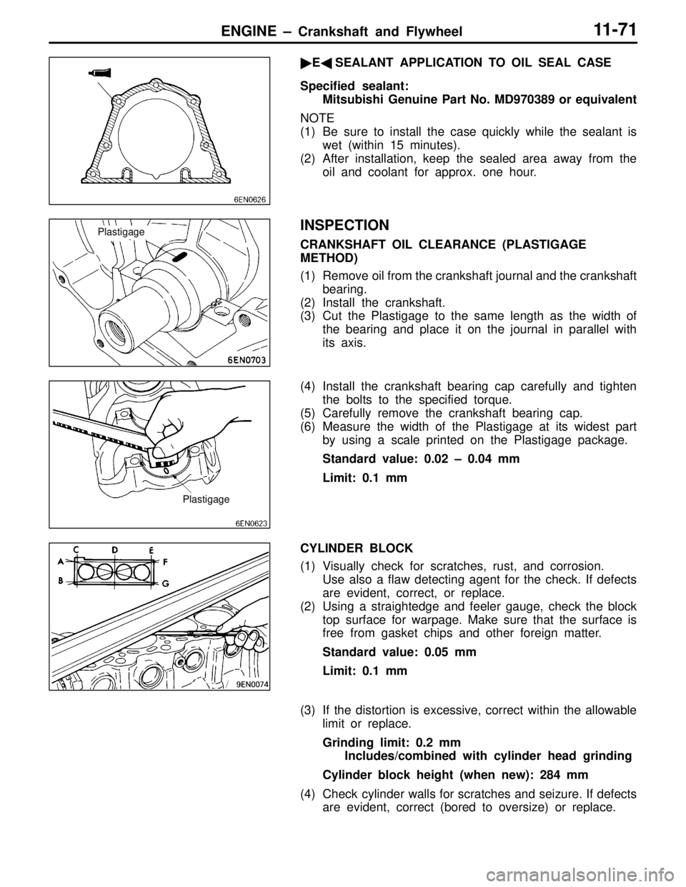
Crankshaft journal outside diameterCylinder block bearing boreCrankshaft bearing
Identification colorSize mmIdentification markIdentification mark or color
Yellow56.994 – 57.00000 or Black
11 or Green
22 or Yellow
None56.988 – 56.99401 or Green
12 or Yellow
23 or None
White56.982 – 56.98802 or Yellow
13 or None
24 or Blue
For example, if the crankshaft journal outside diameter
ID color is “yellow” and cylinder block bearing bore ID
mark is “1”, select a bearing whose ID mark is “1”.
If there is no ID color paint on the crankshaft, measure
the journal outside diameter and select a bearing
appropriate for the measured value.
(2) Install the bearings having an oil groove to the cylinder
block.
(3) Install the bearings having no oil groove to the bearing
cap.
�C�BEARING CAP / BEARING CAP BOLT
INSTALLATION
(1) Install the bearing caps so the arrow points to the timing
belt side.
(2) Before installing the bearing cap bolts, check that the
shank length of each bolt meets the limit. If the limit is
exceeded, replace the bolt.
Limit: Max. 71.1 mm
(3) Apply engine oil to the threaded portion and bearing
surface of the bolt.Crankshaft bearing size
identification mark or color
Identification
mark or color
UpperGroove
Lower
9EN0477
Shank length
Page 96 of 558

ENGINE – Crankshaft and Flywheel11-71
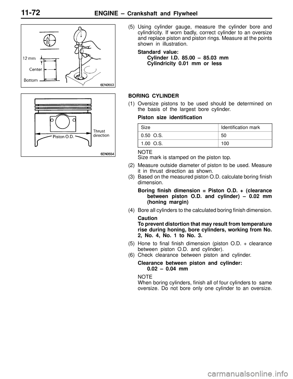
�E�SEALANT APPLICATION TO OIL SEAL CASE
Specified sealant:
Mitsubishi Genuine Part No. MD970389 or equivalent
NOTE
(1) Be sure to install the case quickly while the sealant is
wet (within 15 minutes).
(2) After installation, keep the sealed area away from the
oil and coolant for approx. one hour.
INSPECTION
CRANKSHAFT OIL CLEARANCE (PLASTIGAGE
METHOD)
(1) Remove oil from the crankshaft journal and the crankshaft
bearing.
(2) Install the crankshaft.
(3) Cut the Plastigage to the same length as the width of
the bearing and place it on the journal in parallel with
its axis.
(4) Install the crankshaft bearing cap carefully and tighten
the bolts to the specified torque.
(5) Carefully remove the crankshaft bearing cap.
(6) Measure the width of the Plastigage at its widest part
by using a scale printed on the Plastigage package.
Standard value: 0.02 – 0.04 mm
Limit: 0.1 mm
CYLINDER BLOCK
(1) Visually check for scratches, rust, and corrosion.
Use also a flaw detecting agent for the check. If defects
are evident, correct, or replace.
(2) Using a straightedge and feeler gauge, check the block
top surface for warpage. Make sure that the surface is
free from gasket chips and other foreign matter.
Standard value: 0.05 mm
Limit: 0.1 mm
(3) If the distortion is excessive, correct within the allowable
limit or replace.
Grinding limit: 0.2 mm
Includes/combined with cylinder head grinding
Cylinder block height (when new): 284 mm
(4) Check cylinder walls for scratches and seizure. If defects
are evident, correct (bored to oversize) or replace.
Plastigage
Plastigage
Page 97 of 558

ENGINE – Crankshaft and Flywheel11-72
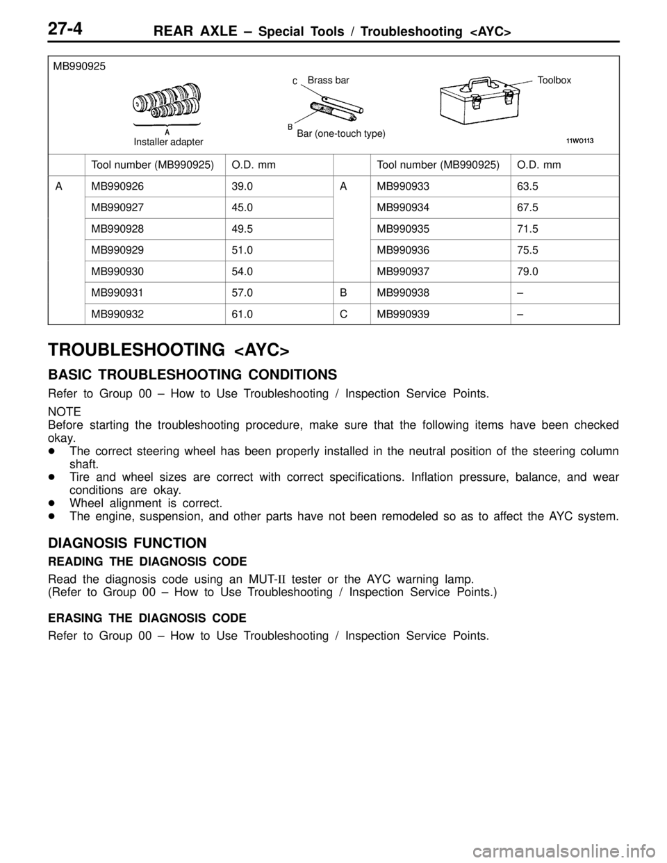
(5) Using cylinder gauge, measure the cylinder bore and
cylindricity. If worn badly, correct cylinder to an oversize
and replace piston and piston rings. Measure at the points
shown in illustration.
Standard value:
Cylinder I.D. 85.00 – 85.03 mm
Cylindricity 0.01 mm or less
BORING CYLINDER
(1) Oversize pistons to be used should be determined on
the basis of the largest bore cylinder.
Piston size identification
SizeIdentification mark
0.50 O.S.50
1.00 O.S.100
NOTE
Size mark is stamped on the piston top.
(2) Measure outside diameter of piston to be used. Measure
it in thrust direction as shown.
(3) Based on the measured piston O.D. calculate boring finish
dimension.
Boring finish dimension = Piston O.D. + (clearance
between piston O.D. and cylinder) – 0.02 mm
(honing margin)
(4) Bore all cylinders to the calculated boring finish dimension.
Caution
To prevent distortion that may result from temperature
rise during honing, bore cylinders, working from No.
2, No. 4, No. 1 to No. 3.
(5) Hone to final finish dimension (piston O.D. + clearance
between piston O.D. and cylinder).
(6) Check clearance between piston and cylinder.
Clearance between piston and cylinder:
0.02 – 0.04 mm
NOTE
When boring cylinders, finish all of four cylinders to same
oversize. Do not bore only one cylinder to an oversize.
Page 200 of 558

REAR AXLE – Special Tools / Troubleshooting 27-4
MB990925
Brass bar
Bar (one-touch type)Toolbox
Installer adapter
Tool number (MB990925)O.D. mmTool number (MB990925)O.D. mm
AMB99092639.0AMB99093363.5
MB99092745.0MB99093467.5
MB99092849.5MB99093571.5
MB99092951.0MB99093675.5
MB99093054.0MB99093779.0
MB99093157.0BMB990938–
MB99093261.0CMB990939–
TROUBLESHOOTING
BASIC TROUBLESHOOTING CONDITIONS
Refer to Group 00 – How to Use Troubleshooting / Inspection Service Points.
NOTE
Before starting the troubleshooting procedure, make sure that the following items have been checked
okay.
�The correct steering wheel has been properly installed in the neutral position of the steering column
shaft.
�Tire and wheel sizes are correct with correct specifications. Inflation pressure, balance, and wear
conditions are okay.
�Wheel alignment is correct.
�The engine, suspension, and other parts have not been remodeled so as to affect the AYC system.
DIAGNOSIS FUNCTION
READING THE DIAGNOSIS CODE
Read the diagnosis code using an MUT-II tester or the AYC warning lamp.
(Refer to Group 00 – How to Use Troubleshooting / Inspection Service Points.)
ERASING THE DIAGNOSIS CODE
Refer to Group 00 – How to Use Troubleshooting / Inspection Service Points.