Page 83 of 558
 Check oil holes for clogging.
(2) Check journals for seizure, damage and contact with
bearing. If there is anythi")
ENGINE – Front Case, Counterbalance Shaft and Oil Pan11-58
COUNTERBALANCE SHAFT
(1) Check oil holes for clogging.
(2) Check journals for seizure, damage and contact with
bearing. If there is anything wrong with the journal, replace
the counterbalance shaft, bearing or front case assembly.
OIL COOLER BY-PASS VALVE (ENGINE WITH AIR
COOLING TYPE OIL COOLER)
(1) Make sure that the valve moves smoothly.
(2) Ensure that the dimension (L) measures the standard
valve under normal temperature and humidity.
Standard value (L): 34.5 mm
(3) The dimension must be the standard value when
measured after the valve has been dipped in 100°C oil.
Standard value (L): 40 mm or more
OIL PUMP
(1) Assemble the oil pump gear to the front case and rotate
it to ensure smooth rotation with no looseness.
(2) Ensure that there is no ridge wear on the contact surface
between the front case and the gear surface of the oil
pump cover.
(3) Check the side clearance.
Standard value:
Drive gear 0.08 – 0.14 mm
Driven gear 0.06 – 0.12 mm
Valve
Page 84 of 558
ENGINE – Piston and Connecting Rod11-59
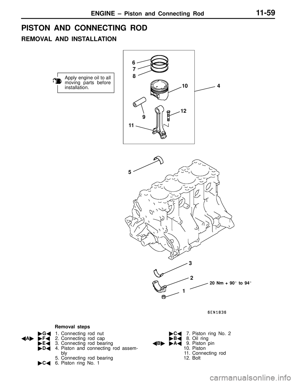
PISTON AND CONNECTING ROD
REMOVAL AND INSTALLATION
Apply engine oil to all
moving parts before
installation.
12 34
56
7
8
910
1112
20 Nm + 90� to 94�
Removal steps
�G�1. Connecting rod nut
�A��F�2. Connecting rod cap
�E�3. Connecting rod bearing
�D�4. Piston and connecting rod assem-
bly
5. Connecting rod bearing
�C�6. Piston ring No. 1�C�7. Piston ring No. 2
�B�8. Oil ring
�B��A�9. Piston pin
10. Piston
11. Connecting rod
12. Bolt
Page 85 of 558
ENGINE – Piston and Connecting Rod11-60
REMOVAL SERVICE POINTS
�A�CONNECTING ROD CAP REMOVAL
(1) Mark the cylinder number on the side of the connecting
rod big end for correct reassembly.
(2) Keep the removed connecting rods, caps, and bearings
in order according to the cylinder number.
�B�PISTON PIN REMOVAL
(1) Insert the special tool, Push Rod, into the piston from
the side on which the front mark is stamped in the piston
head, and attach the guide C to the push rod end.
(2) Place the piston and connecting rod assembly on the
special tool, Piston Pin Setting Base, with the front mark
facing upward.
(3) Using a press, remove the piston pin.
NOTE
Keep the disassembled pistons, piston pins and
connecting rods in order according to the cylinder number.
Page 86 of 558
 Measure the following dimensions of the piston, piston
pin and connecting rod.
A: Piston pin insert")
ENGINE – Piston and Connecting Rod11-61
INSTALLATION SERVICE POINTS
�A�PISTON PIN INSTALLATION
(1) Measure the following dimensions of the piston, piston
pin and connecting rod.
A: Piston pin insertion hole length
B: Distance between piston bosses
C: Piston pin length
D: Connecting rod small end width
(2) Obtain dimension L (to be used later) from the above
measurements by using by following formula.
L =
(A – C) – (B – D)
2
(3) Insert the special tool, Push Rod, into the piston pin and
attach the guide A to the push rod end.
(4) Assemble the connecting rod in the piston with their front
marks facing the same direction.
(5) Apply engine oil to the entire periphery of the piston pin.
(6) Insert the piston pin, push rod and guide A assembly
having assembled in step (3) from the guide A side into
the piston pin hole on the front marked side.
(7) Screw the guide B into the guide A until the gap between
both guides amounts to the value L obtained in step
(2) plus 3 mm.
(8) Place the piston and connecting rod assembly onto the
piston setting base with the front marks directed upward.
(9) Press-fit the piston pin using a press.
If the press-fitting force required is less than the standard
value, replace the piston and piston pin set or/and the
connecting rod.
Standard value: 7,350 – 17,200 N
3 mm + L
Page 87 of 558
ENGINE – Piston and Connecting Rod11-62
(10)Check that the piston moves smoothly
�B�OIL RING INSTALLATION
(1) Fit the oil ring spacer into the piston ring groove.
NOTE
1. The side rails and spacer may be installed in either
direction.
2. New spacers and side rails are colored for
identification of their sizes.
SizeIdentification color
StandardNone
0.50 mm oversizeRed
1.00 mm oversizeYellow
(2) Install the upper side rail.
To install the side rail, first fit one end of the rail into
the piston groove, then press the remaining portion into
position by finger. See illustration.
Use of ring expander to expand the side rail end gap
can break the side rail, unlike other piston rings.
Caution
Do not use piston ring expander when installing side
rail.
(3) Install the lower side rail in the same procedure as
described in step (2).
(4) Make sure that the side rails move smoothly in either
direction.
6EN1237
Lower side railSpacer
Upper
side rail
1EN0269
Side rail gap
Page 88 of 558
 Using piston ring expander, fit No. 2 and then No. 1 piston
ring into position.
NOTE
1. The ring end")
ENGINE – Piston and Connecting Rod11-63
�C�PISTON RING NO. 2 / PISTON RING NO. 1
INSTALLATION
(1) Using piston ring expander, fit No. 2 and then No. 1 piston
ring into position.
NOTE
1. The ring end is provided with identification mark.
ItemIdentification mark
No. 1 ring1R
No. 2 ring2R
2. Install piston rings with identification mark facing up,
to the piston crown side.
3. Size marks on position rings are as follows.
SizeSize mark
StandardNone
0.50 mm oversize50
1.00 mm oversize100
�D�PISTON AND CONNECTING ROD ASSEMBLY
INSTALLATION
(1) Liberally coat engine oil on the circumference of the piston,
piston ring, and oil ring.
(2) Arrange the piston ring and oil ring gaps (side rail and
spacer) as shown in the figure.
(3) Rotate the crankshaft so that crank pin is on the center
of cylinder bore.
(4) Use suitable thread protectors on the connecting rod bolts
before inserting piston and connecting rod assembly into
the cylinder block.
Care must be taken not to nick the crank pin.
(5) Using a suitable piston ring compressor tool, install the
piston and connecting rod assembly into the cylinder block.
�E�CONNECTING ROD BEARINGS INSTALLATION
When the bearing needs replacing, select and install a proper
bearing by the following procedure.
(1) Measure the crankshaft pin diameter and confirm its
classification from the following table. In the case of a
crankshaft supplied as a service part, identification colors
of its pins are painted at the positions shown in the
illustration.
9EN0524
Identification mark
Identification mark
Side mark
No. 1
No. 2
Timing belt side
Page 89 of 558
 The connecting rod bearing identification mark is stamped
at the position shown in the illustration.
Crankshaft pinConnecting rod bearing
Classi-
fication")
ENGINE – Piston and Connecting Rod11-64
(2) The connecting rod bearing identification mark is stamped
at the position shown in the illustration.
Crankshaft pinConnecting rod bearing
Classi-
ficationIdentifica-
tion markIdentifi-
cation
colorO. D. mmIdenti-
fication
markThickness mm
Produc-
tion partService
part
1NoneYellow44.995 – 45.00001.483 – 1.487
2NoneNone44.985 – 44.99511.487 – 1.491
3NoneWhite44.980 – 44.98521.491 – 1.495
Connecting rod I.D.: 48.000 – 48.015 mm
(3) Select a proper bearing from the above table on the basic
of the identification data confirmed under items (1) and
(2).
[Example]
If the measured value of a crankshaft pin outer diameter
is 44.996 mm, the pin is classified as “1” in the table.
In case the crankshaft is also replaced by a spare part,
check the identification colors of the pins painted on the
new crankshaft. If the color is yellow, for example, the
pin is classified as “1”. In the above cases, select the
connection rod bearing having identification mark “0”.
�F�CONNECTING ROD CAP INSTALLATION
(1) Verifying the mark made during disassembly, install the
bearing cap to the connecting rod. If the connecting rod
is new with no index mark, make sure that the bearing
locking notches come on the same side as shown.
(2) Make sure that the connecting rod big end side clearance
meets the specification.
Standard value: 0.10 – 0.25 mm
Limit: 0.4 mm
Identification mark
Page 90 of 558

ENGINE – Piston and Connecting Rod11-65
�G�CONNECTING ROD CAP NUT INSTALLATION
Caution
If the cylinder head has been installed before installing
the connecting rod cap nut, be sure to remove the spark
plugs.
(1) Since the connecting rod cap bolts and nuts are torqued
using the plastic area tightening method, the bolts should
be examined BEFORE reuse. If the bolt threads are
“necked down”, the bolt should be replaced.
Necking can be checked by running a nut with fingers
to the full length of the bolt threads. If the nut does not
run down smoothly, the bolt should be replaced.
(2) Before installation of each nut, apply engine oil to the
thread portion and bearing surface of the nut.
(3) Install each nut to the bolt and tighten it with fingers.
Then tighten the nuts alternately to install the cap properly.
(4) Tighten the nuts to a torque of 20 Nm.
(5) Make a paint mark on the head of each nut.
(6) Make a paint mark on the bolt end at the position 90°
to 94° from the paint mark made on the nut in the direction
of tightening the nut.
(7) Give a 90° to 94° turn to the nut and make sure that
the paint mark on the nut and that on the bolt are in
alignment.
Caution
1. If the nut is turned less than 90°, proper fastening
performance may not be expected. When
tightening the nut, therefore, be careful to give
a sufficient turn to it.
2. If the nut is overtightened (exceeding 94°), loosen
the nut completely and then retighten it by
repeating the tightening procedure from step (1).
INSPECTION
PISTON RING
(1) Check the piston ring for damage, excessive wear, and
breakage and replace if defects are evident. If the piston
has been replaced with a new one, the piston rings must
also be replaced with new ones.
(2) Check for the clearance between the piston ring and
ring groove. If the limit is exceeded, replace the ring or
piston, or both.
Standard value:
No. 1 ring 0.04 – 0.075 mm
No. 2 ring 0.02 – 0.06 mm
Limit: 0.1 mm
6AE0298
90° to 94°Paint mark
Paint
mark
NutBolt