1999 LAND ROVER DISCOVERY warning
[x] Cancel search: warningPage 1206 of 1529

AIR CONDITIONING
DESCRIPTION AND OPERATION 82-17
Timed recirculated air
The timed recirculated air mode sets the inlet air source to recirculated air for 5 ± 1 minutes, after which it automatically
reverts to fresh air. Timed recirculated air can be manually selected:
lIn the automatic mode, by pressing the fresh/recirculated air switch for 1.5 seconds or more; the audible warning
sounds twice.
lIn the economy or defrost modes, by pressing the fresh/recirculated air switch for less than 1.5 seconds; the
audible warning sounds once.
Latched recirculated air
The inlet air source can be latched to recirculated air:
lIn the automatic mode, by pressing the fresh/recirculated air switch for less than 1.5 seconds; the audible
warning sounds once.
lIn the economy or defrost modes, by pressing the fresh/recirculated air switch for 1.5 seconds or more; the
audible warning sounds twice.
Blower control
The ATC ECU operates a blower relay, power transistor and power relay to run the blower at one of 31 stepped
speeds. All speed steps are available in the automatic modes of blower control. In the manual mode, speed steps 3,
10, 16, 22 and 31 are used to provide slow, three intermediate and fast blower speeds. The ATC ECU energises the
blower relay and modulates the power transistor to operate the blower for speed steps 1 to 30. For speed step 31, the
ATC ECU energises the power relay, which switches the earth side of the blower motor direct to earth, bypassing the
power transistor.
In the automatic, economy and defrost modes, blower speed is corrected for vehicle speed to compensate for the
increase in ram effect on the inlet air as the vehicle speed increases. Correction begins at approximately 50 km/h,
when blower speed is progressively decreased as vehicle speed increases, until a maximum decrease of 13 steps
occurs at 123 km/h. Similarly, blower speed increases as vehicle speed decreases down to approximately 50 km/h.
In the automatic and economy modes, if the LH or RH temperature is set to LO or HI, the blower runs at maximum
speed with correction only for vehicle speed. If both the LH and RH outlet air temperatures are set to a specific
temperature, blower speed corrections are added to compensate for the heater coolant temperature, external air
temperature, and the solar load acting on the vehicle:
lDuring warm-up, the blower speed is set to 3 while the heater coolant temperature is below approximately 20 °C
(68 °F). From approximately 20 °C (68 °F), the blower speed is progressively increased as the coolant
temperature increases, until maximum speed is set at approximately 50 °C (122 °F).
lDuring cool down, blower speed is set to 3, for 5 seconds after the system is switched on. Over the following 6
seconds, the blower speed is progressively increased up to maximum speed.
lAs the temperature in the cabin approaches the selected temperatures, blower speed is progressively reduced
until, once the selected temperatures have been established, blower speed stabilises at approximately 6.
lSolar heating correction is employed when air distribution is set to face level or to face and footwells. The
correction progressively increases the blower speed, up to a maximum of 9 steps, with increasing values of solar
heating.
Page 1207 of 1529

AIR CONDITIONING
82-18DESCRIPTION AND OPERATION
Air distribution control
To control the air distribution within the cabin the ATC ECU signals the servo motor controlling the distribution flaps
in the heater assembly to move to the flaps to the appropriate position.
In the automatic and economy modes, if the LH or RH temperature selections are set to LO or HI, air distribution is
fixed as follows:
lIf one is set to LO and one is set to a specific temperature, to face level only.
lIf one is set to HI and one is set to a specific temperature, to footwells only.
lIf one is set to LO and one is set to HI, to face level and footwells.
When specific LH and RH temperature selections are set, air distribution is determined from the target air outlet
temperatures. For higher target air outlet temperatures, air distribution is set to footwells only. For lower target air
outlet temperatures, air distribution is set to face level only. For intermediate target air outlet temperatures, air
distribution is set to face level and footwells. When the air distribution is set to face level and footwells, the ATC ECU
varies the bias between the footwells and the face level outlets, in three stages, to provide a gradual transition of air
distribution from footwells only to face level only. The three stages of bias are also employed when the air distribution
is manually selected to face level and footwells.
During warm-up, the air distribution changes to face level and footwells for a period, then reverts to footwells only.
The period of air distribution at face level and footwells can be cancelled by pressing and holding the on/off and defrost
mode switches, then turning the ignition switch from off to on. Pressing and holding the AUTO and defrost switches,
then turning the ignition switch from off to on, restores the period of air distribution at face level and footwells.
Compressor control
To engage the compressor clutch, the ATC ECU outputs a compressor clutch request to the ECM, which then
energises the A/C compressor clutch relay. Compressor operation is governed by the evaporator outlet air
temperature, at one of two settings, dependent on the amount of cooling required. When more cooling is required, the
compressor clutch request is output if evaporator outlet air temperature increases to 4 °C (39 °F) and cancelled when
it decreases to 3 °C (37 °F). When less cooling is required, the compressor clutch request is output if evaporator outlet
air temperature increases to 11 °C (52 °F) and cancelled when it decreases to 10 °C (50 °F).
Engine cooling fan control
While the A/C system is on, operation of the electric engine cooling fan, to assist refrigerant condenser operation, is
determined by a combination of vehicle speed and external air temperature. When cooling fan operation is required,
the ATC ECU outputs a cooling fan request to the ECM, which then energises the cooling fan relay. The cooling fan
request is output if vehicle speed is 80 km/h or less while the external air temperature is 28 °C (82 °F) or more. The
request is cancelled, and the cooling fan switched off, if either the vehicle speed increases to 100 km/h, or the external
air temperature decreases to 25 °C (77 °F).
Default settings
If the battery power supply to the ATC ECU is disrupted for any reason, e.g. battery disconnected, the system reverts
to default settings when the battery power supply is restored. Default settings are:
lTemperature indications in °C (in some markets a conversion connector is fitted to the ATC ECU to change the
default temperature scale to °F).
lLH and RH outlet temperatures of 22 °C (72 °F).
laudible warning switched on.
lWarm-up air distribution (to face level and footwells) function switched on.
lIf the system is first switched on using the A/C on/off switch, the automatic mode is engaged, regardless of the
settings in use when the battery was disconnected.
Page 1208 of 1529

AIR CONDITIONING
DESCRIPTION AND OPERATION 82-19
Diagnostics
The ATC ECU performs a diagnostic check each time the ignition is switched on. To avoid nuisance fault indications
at low light levels, the sunlight sensor is omitted from the diagnostic check. If a fault is detected, the audible warning
sounds three times and the AUTO window on the control panel display flashes for 20 seconds. The ATC ECU then
reverts to normal control but uses a default value or strategy for the detected fault. Faults are identified by performing
a manual diagnostic check of the system.
A manual diagnostic check includes a check of the sunlight sensor, and is initiated by pressing and holding the AUTO
switch and the air distribution switch, then turning the ignition switch from off to on. The audible warning sounds once
and the indications on the control panel display illuminate. FC is shown in the LH temperature window and the results
of the check are shown as a two digit fault code in the RH temperature window. If a fault is detected, the audible
warning sounds three times and the AUTO window on the display flashes on and off for 20 seconds. If more than one
fault is detected, the fault codes cycle in numerical order, at 1 Hz. The audible warning sounds as each fault code is
shown. In low light conditions, to avoid false sunlight sensor fault indications, the sunlight sensor should be illuminated
with a strong light source.
Diagnostic fault codes and fault descriptions
Code Component Fault Default value/strategy
00 - No fault found -
11 In-car temperature sensor Open or short circuit 25°C (77°F)
12 Ambient temperature sensor Open or short circuit 10°C (50°F)
Cooling fan permanently on
Display shows "- -" if external air
temperature selected
13 Thermistor Open or short circuit 0°C (32°F)
14 Heater coolant temperature sensor Open or short circuit 70°C (158°F)
21 Sunlight sensor, left output Open or short circuit No solar heating correction
22 Sunlight sensor, right output Open or short circuit No solar heating correction
31 LH temperature servo motor Open or short circuit
Motor or flap mechanism seizedServo motor locked in position
32 RH temperature servo motor Open or short circuit
Motor or flap mechanism seizedServo motor locked in position
33 Distribution servo motor Open or short circuit
Motor or flap mechanism seizedServo motor locked in position
Page 1216 of 1529
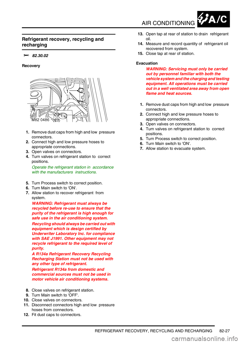
AIR CONDITIONING
REFRIGERANT RECOVERY, RECYCLING AND RECHARGING 82-27
REFRIGERANT RECOVERY, RECYCLING AND RECHARGING
Refrigerant recovery, recycling and
recharging
$% 82.30.02
Recovery
1.Remove dust caps from high and low pressure
connectors.
2.Connect high and low pressure hoses to
appropriate connections.
3.Open valves on connectors.
4.Turn valves on refrigerant station to correct
positions.
Operate the refrigerant station in accordance
with the manufacturers instructions.
5.Turn Process switch to correct position.
6.Turn Main switch to 'ON'.
7.Allow station to recover refrigerant from
system.
WARNING: Refrigerant must always be
recycled before re-use to ensure that the
purity of the refrigerant is high enough for
safe use in the air conditioning system.
Recycling should always be carried out with
equipment which is design certified by
Underwriter Laboratory Inc. for compliance
with SAE J1991. Other equipment may not
recycle refrigerant to the required level of
purity.
A R134a Refrigerant Recovery Recycling
Recharging Station must not be used with
any other type of refrigerant.
Refrigerant R134a from domestic and
commercial sources must not be used in
motor vehicle air conditioning systems.
8.Close valves on refrigerant station.
9.Turn Main switch to 'OFF'.
10.Close valves on connectors.
11.Disconnect connectors high and low pressure
hoses from connectors.
12.Fit dust caps to connectors. 13.Open tap at rear of station to drain refrigerant
oil.
14.Measure and record quantity of refrigerant oil
recovered from system.
15.Close tap at rear of station.
Evacuation
WARNING: Servicing must only be carried
out by personnel familiar with both the
vehicle system and the charging and testing
equipment. All operations must be carried
out in a well ventilated area away from open
flame and heat sources.
1.Remove dust caps from high and low pressure
connectors.
2.Connect high and low pressure hoses to
appropriate connections.
3.Open valves on connectors.
4.Turn valves on refrigerant station to correct
positions.
5.Turn Process switch to correct position.
6.Turn Main switch to 'ON'.
7.Allow station to evacuate system.
Page 1261 of 1529
WIPERS AND WASHERS
84-26 REPAIRS
Switch - wiper and washer - windscreen
$% 84.15.34
WARNING: It is imperative that before any work
is undertaken on the SRS system the appropriate
information is read thoroughly.
Remove
1.Remove rotary coupler.
+ RESTRAINT SYSTEMS, REPAIRS,
Rotary coupler.
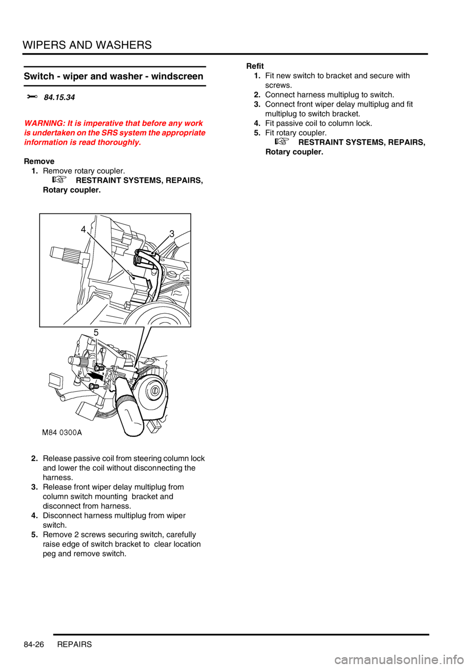
2.Release passive coil from steering column lock
and lower the coil without disconnecting the
harness.
3.Release front wiper delay multiplug from
column switch mounting bracket and
disconnect from harness.
4.Disconnect harness multiplug from wiper
switch.
5.Remove 2 screws securing switch, carefully
raise edge of switch bracket to clear location
peg and remove switch. Refit
1.Fit new switch to bracket and secure with
screws.
2.Connect harness multiplug to switch.
3.Connect front wiper delay multiplug and fit
multiplug to switch bracket.
4.Fit passive coil to column lock.
5.Fit rotary coupler.
+ RESTRAINT SYSTEMS, REPAIRS,
Rotary coupler.
Page 1271 of 1529
CHARGING AND STARTING
86-1-6 REPAIRS
Starter motor - diesel
$% 86.60.01
Remove
1.Release fixings and remove battery cover.
2.Disconnect battery earth lead.
3.Raise front of vehicle.
WARNING: Do not work on or under a
vehicle supported only by a jack. Always
support the vehicle on safety stands.
4.Remove underbelly panel.
+ EXTERIOR FITTINGS, REPAIRS,
Panel - underbelly.
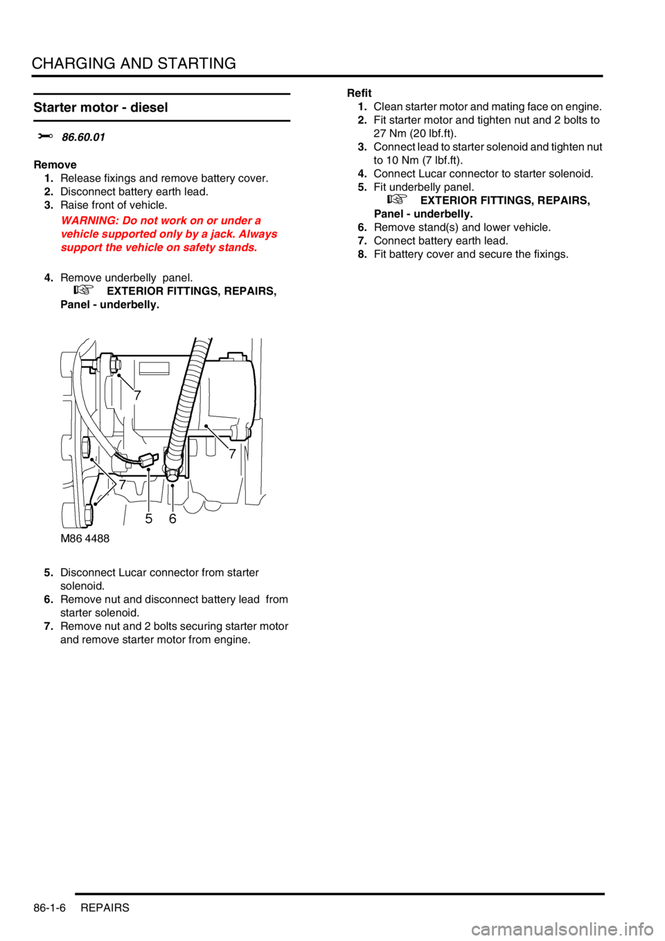
5.Disconnect Lucar connector from starter
solenoid.
6.Remove nut and disconnect battery lead from
starter solenoid.
7.Remove nut and 2 bolts securing starter motor
and remove starter motor from engine.Refit
1.Clean starter motor and mating face on engine.
2.Fit starter motor and tighten nut and 2 bolts to
27 Nm (20 lbf.ft).
3.Connect lead to starter solenoid and tighten nut
to 10 Nm (7 lbf.ft).
4.Connect Lucar connector to starter solenoid.
5.Fit underbelly panel.
+ EXTERIOR FITTINGS, REPAIRS,
Panel - underbelly.
6.Remove stand(s) and lower vehicle.
7.Connect battery earth lead.
8.Fit battery cover and secure the fixings.
Page 1272 of 1529
CHARGING AND STARTING
REPAIRS 86-1-7
Starter motor - V8
$% 86.60.01
Remove
1.Release fixings and remove battery cover.
2.Disconnect battery earth lead.
3.Raise front of vehicle.
WARNING: Do not work on or under a
vehicle supported only by a jack. Always
support the vehicle on safety stands.
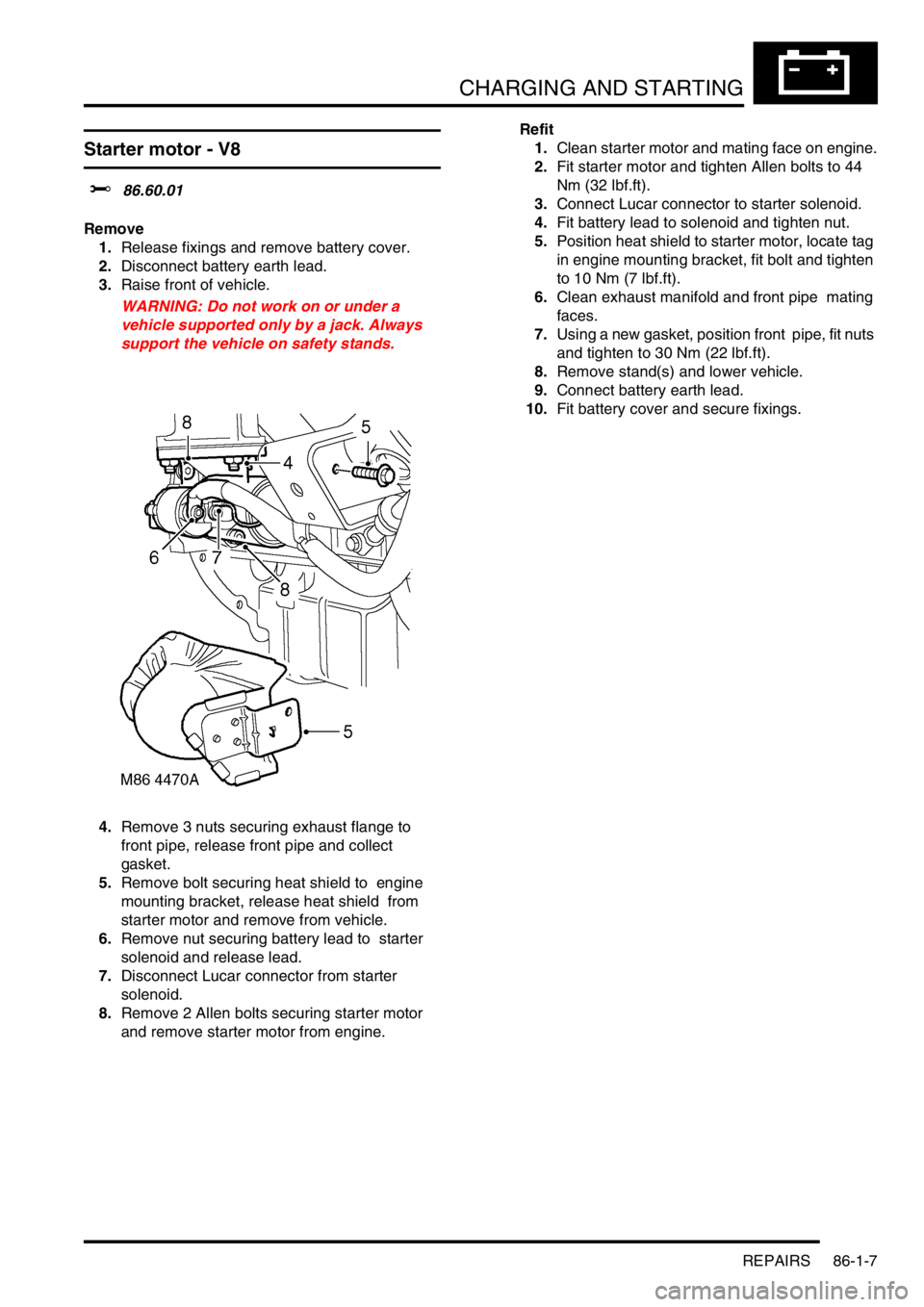
4.Remove 3 nuts securing exhaust flange to
front pipe, release front pipe and collect
gasket.
5.Remove bolt securing heat shield to engine
mounting bracket, release heat shield from
starter motor and remove from vehicle.
6.Remove nut securing battery lead to starter
solenoid and release lead.
7.Disconnect Lucar connector from starter
solenoid.
8.Remove 2 Allen bolts securing starter motor
and remove starter motor from engine. Refit
1.Clean starter motor and mating face on engine.
2.Fit starter motor and tighten Allen bolts to 44
Nm (32 lbf.ft).
3.Connect Lucar connector to starter solenoid.
4.Fit battery lead to solenoid and tighten nut.
5.Position heat shield to starter motor, locate tag
in engine mounting bracket, fit bolt and tighten
to 10 Nm (7 lbf.ft).
6.Clean exhaust manifold and front pipe mating
faces.
7.Using a new gasket, position front pipe, fit nuts
and tighten to 30 Nm (22 lbf.ft).
8.Remove stand(s) and lower vehicle.
9.Connect battery earth lead.
10.Fit battery cover and secure fixings.
Page 1286 of 1529
LIGHTING
REPAIRS 86-2-13
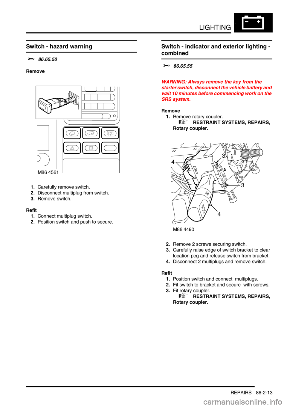
Switch - hazard warning
$% 86.65.50
Remove
1.Carefully remove switch.
2.Disconnect multiplug from switch.
3.Remove switch.
Refit
1.Connect multiplug switch.
2.Position switch and push to secure.
Switch - indicator and exterior lighting -
combined
$% 86.65.55
WARNING: Always remove the key from the
starter switch, disconnect the vehicle battery and
wait 10 minutes before commencing work on the
SRS system.
Remove
1.Remove rotary coupler.
+ RESTRAINT SYSTEMS, REPAIRS,
Rotary coupler.
2.Remove 2 screws securing switch.
3.Carefully raise edge of switch bracket to clear
location peg and release switch from bracket.
4.Disconnect 2 multiplugs and remove switch.
Refit
1.Position switch and connect multiplugs.
2.Fit switch to bracket and secure with screws.
3.Fit rotary coupler.
+ RESTRAINT SYSTEMS, REPAIRS,
Rotary coupler.