1999 LAND ROVER DISCOVERY warning
[x] Cancel search: warningPage 932 of 1529

RESTRAINT SYSTEMS
REPAIRS 75-29
Rotary coupler
$% 76.74.20
WARNING: It is imperative that before any work
is undertaken on the SRS system the appropriate
information is read thoroughly.
WARNING: Always disconnect both battery leads
before beginning work on the SRS system.
Disconnect the negative battery lead first. Never
reverse connect the battery.
Remove
1.Remove the key from the starter switch.
Disconnect both battery leads, negative lead
first. Wait ten minutes before starting work.
2.Remove steering wheel.
+ STEERING, REPAIRS, Steering
wheel.
3.Remove steering column nacelle.
+ STEERING, REPAIRS, Nacelle -
steering column.4.Release rotary coupler multiplug from bracket
and disconnect from harness.
5.Disconnect rotary coupler multiplug from
harness.
6.Remove rotary coupler.
Refit
1.Fit rotary coupler to steering column and
connect multiplug to harness.
2.Connect rotary coupler multiplug to harness
and secure to bracket.
3.Fit steering column nacelle.
+ STEERING, REPAIRS, Nacelle -
steering column.
4.Fit steering wheel.
+ STEERING, REPAIRS, Steering
wheel.
Page 954 of 1529

EXTERIOR FITTINGS
REPAIRS 76-2-7
Panel - underbelly
$% 76.10.50
Remove
1.Raise front of vehicle, support underbody and
lower front axle
WARNING: Do not work on or under a
vehicle supported only by a jack. Always
support the vehicle on safety stands.
2.Remove nut securing drag link to drop arm.
3.Using tool LRT-57-036 break taper joint and
release drag link from drop arm.
4.Remove nut and bolt securing steering damper
to chassis and remove damper.
5.Remove 7 screws securing underbelly panel.
6.Remove underbelly panel.
7.Remove 7 studs securing sound deadening to
underbelly panel.
8.Remove sound deadening.
Refit
1.Position sound deadening to underbelly panel
and secure with studs.
2.Fit underbelly panel and secure with screws.
3.Position steering damper, fit nut and bolt and
tighten to 125 Nm (92 lbf.ft)
4.Fit drag link to drop arm and tighten nut to 80
Nm (59 lbf.ft).
5.Lower front of vehicle.
Mirror - exterior - electric
$% 76.10.57
Remove
1.Release cheater panel from front door.
2.Remove anti-rattle foam pad from front door.
3.Release mirror multiplug from mounting plate.
4.Disconnect multiplug from mirror.
5.Remove 3 bolts securing mirror to door.
6.Remove mirror and collect mounting plate.
Refit
1.Fit mirror and mounting plate to door.
2.Fit bolts securing mirror to door and tighten to
4 Nm (3 lbf.ft).
3.Connect multiplug to mirror.
4.Secure multiplug to mounting plate.
5.Fit anti-rattle foam pad to front door.
6.Secure cheater panel to front door.
Page 991 of 1529

SCREENS
76-4-2 REPAIRS
Windscreen
$% 76.81.01
Introduction
The following equipment is required:
lCutting wire and handles.
lKent cutting knife.
lGlazing knife.
lWindscreen repair kit.
lSealant applicator gun.
lSuction cups.
lA felt covered table or stand to support glass.
WARNING: Wear protective gloves when
handling glass, solvents and primers.
WARNING: Wear suitable eye protection when
removing and refitting glass.
WARNING: If glass has splintered, protect eyes
and operate demister blower to remove glass
from heater ducts. Use a vacuum cleaner to
remove glass from fascia, carpet and seats.Remove
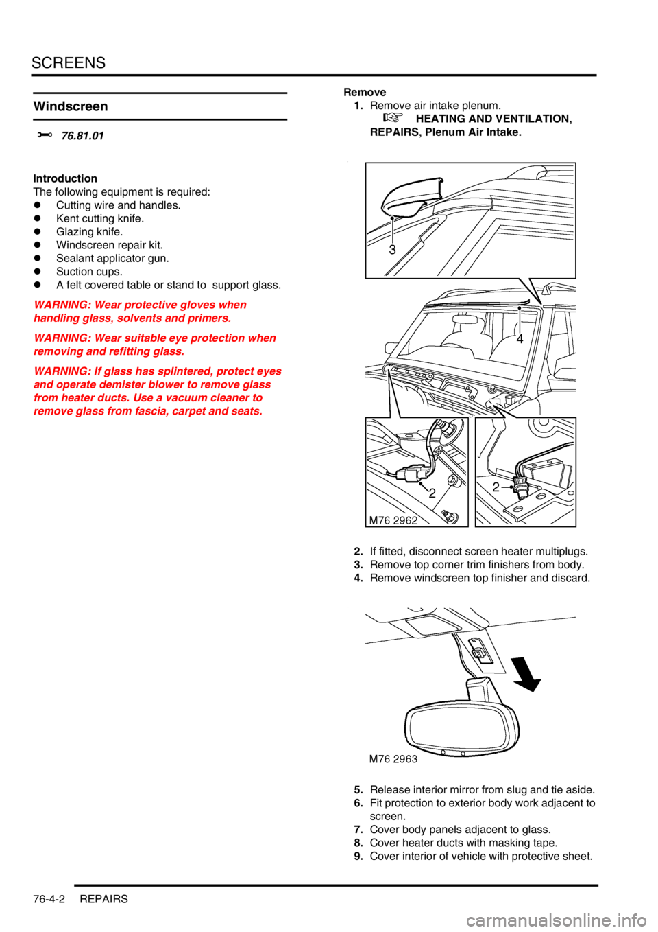
1.Remove air intake plenum.
+ HEATING AND VENTILATION,
REPAIRS, Plenum Air Intake.
2.If fitted, disconnect screen heater multiplugs.
3.Remove top corner trim finishers from body.
4.Remove windscreen top finisher and discard.
5.Release interior mirror from slug and tie aside.
6.Fit protection to exterior body work adjacent to
screen.
7.Cover body panels adjacent to glass.
8.Cover heater ducts with masking tape.
9.Cover interior of vehicle with protective sheet.
Page 993 of 1529

SCREENS
76-4-4 REPAIRS
15.Apply a continuous bead of sealant to sealant
face on screen as shown.
16.With assistance, lift screen into place and align
to screen supports and tape. Ensure top
finisher is located into correct position. Lightly
press glass to fully seat sealer.
CAUTION: Do not apply heavy pressure to
the sides of the windscreen. Lightly press
windscreen from centre outwards until
edges are to required gap. Pushing sides
into position can bend windscreen and lead
to cracking in service.
17.Remove protective covers and tape.
18.Test sealer for leaks, apply additional sealer if
necessary. If water is used, allow sealer to dry
before testing. Spray water around glass and
check for leaks. Mark any area that leaks. Dry
glass and sealer then apply additional sealer.
19.Fit interior mirror to slug.
20.If applicable, connect screen heater multiplugs.
21.Fit air intake plenum.
+ HEATING AND VENTILATION,
REPAIRS, Plenum Air Intake.
CAUTION: A curing time of 6 hours is
desirable. During this time leave a window
open to ventilate the vehicle interior. If the
vehicle must be used before the curing time
has elapsed, do not drive at speed or slam
the doors with the windows closed.
CAUTION: Vehicles fitted with a passenger
airbag should not be driven for 24 hours.
Glass - body side - rear
$% 76.81.18
Introduction
The following equipment is required:
lCutting wire and handles.
lKent cutting knife.
lGlazing knife.
lWindscreen repair kit.
lSealant applicator gun.
lSuction cups.
lA felt covered table or stand to support glass.
WARNING: Wear protective gloves when
handling glass, solvents and primers.
WARNING: Wear suitable eye protection when
removing and refitting glass.
Remove
1.If fitted, disconnect coaxial cable from terminal
on glass.
2.Fit protection to exterior body work adjacent to
glass.
3.Cover body panels adjacent to glass.
4.Fit protection to internal trim adjacent to glass.
5.Cover interior of vehicle with protective sheet.
Page 995 of 1529

SCREENS
76-4-6 REPAIRS
Glass - alpine light
$% 76.81.52
Introduction
The following equipment is required:
lCutting wire and handles.
lKent cutting knife.
lGlazing knife.
lWindscreen repair kit.
lSealant applicator gun.
lSuction cups.
lA felt covered table or stand to support glass.
WARNING: Wear protective gloves when
handling glass, solvents and primers.
WARNING: Wear suitable eye protection when
removing and refitting glass.
Remove
1.Fit protection to exterior body work adjacent to
glass.
2.Fit cover over adjacent body work.
3.Fit protection to internal trim adjacent to glass.
4.Cover interior of vehicle with protective sheet.
5.From outside of vehicle, use a Kent knife and
carefully cut through sealant to release glass
from body. Any remaining sealant not
accessible with Kent knife can be severed
using cutting wire or knife.
CAUTION: Hold the cutting wire as close to
the glass as possible to prevent damage to
the body and surrounding trim.
6.Remove glass.
CAUTION: Lay glass on felt covered
supports and be careful not to damage the
obscuration band. Do not stand on edge as
this can cause chips which subsequently
develop into cracks.Refit
1.Carefully remove sealant from body to leave a
smooth surface.
2.With assistance, fit glass without sealant to
body and apply masking tape to establish
reference marks as an alignment aid.
3.Remove glass and place aside.
4.Clean body and sealant face on glass with
solvent.
CAUTION: Do not touch cleaned or primed
surfaces with fingers.
5.Apply etch primer to any bare metal on body.
6.Apply glass primer to sealant face on glass and
allow to cure.
7.Apply primer over etch primer on body.
8.Apply activator over old sealant on body.
9.Allow activator to cure.
10.Fit pre-cut nozzle to sealant cartridge, remove
lid, shake out crystals, and fit cartridge to
applicator gun. If necessary modify the nozzle
to achieve required bead section.
11.Apply a continuous bead of sealant to sealant
face on glass as shown.
Page 1140 of 1529

CORROSION PREVENTION AND SEALING
CORROSION PREVENTION 77-4-7
The checks described above are intended to be visual only. It is not intended that the operator should remove trim
panels, finishers, rubbing strips or sound-deadening materials when checking the vehicle for corrosion and paint
damage.
With the vehicle on a lift, and using an inspection or spot lamp, visually check for the following:
lCorrosion damage and damaged paintwork, condition of underbody sealer on front and rear lower panels, sills
and wheel arches;
lDamage to underbody sealer. Corrosion in areas adjacent to suspension mountings and fuel tank fixings.
NOTE: The presence of small blisters in the underbody sealer is acceptable, providing they do not expose bare metal.
Pay special attention to signs of damage caused to panels or corrosion protection material by incorrect jack
positioning.
WARNING: It is essential to follow the correct jacking and lifting procedures.
With the vehicle lowered, visually check for evidence of damage and corrosion on all visible painted areas, in
particular the following:
lFront edge of bonnet;
lVisible flanges in engine compartment;
lLower body and door panels.
Rectify any bodywork damage or evidence of corrosion found during inspection as soon as is practicable, both to
minimise the extent of the damage and to ensure the long term effectiveness of the factory-applied corrosion
prevention treatment. Where the cost of rectification work is the owner's responsibility, the Dealer must advise the
owner and endorse the relevant documentation accordingly.
Where corrosion has become evident and is emanating from beneath a removable component (e.g. trim panel,
window glass, seat etc.), remove the component as required to permit effective rectification.
Underbody protection repairs
Whenever body repairs are carried out, ensure that full sealing and corrosion protection treatments are reinstated.
This applies both to the damaged areas and also to areas where protection has been indirectly impaired, as a result
either of accident damage or repair operations.
Remove corrosion protection from the damaged area before straightening or panel beating. This applies in particular
to panels coated with wax, PVC underbody sealer, sound deadening pads etc.
WARNING: DO NOT use oxy-acetylene gas equipment to remove corrosion prevention materials. Large
volumes of fumes and gases are liberated by these materials when they burn.
NOTE: Equipment for the removal of tough anti-corrosion sealers offers varying degrees of speed and effectiveness.
The compressed air-operated scraper (NOT an air chisel) offers a relatively quiet mechanical method using an
extremely rapid reciprocating action. Move the operating end of the tool along the work surface to remove the material.
The most common method of removal is by means of a hot air blower with integral scraper.
Another tool, and one of the most efficient methods, is the rapid-cutting 'hot knife'. This tool uses a wide blade and is
quick and versatile, able to be used easily in profiled sections where access is otherwise difficult.
Use the following procedure when repairing underbody coatings:
1Remove existing underbody coatings
2After panel repair, clean the affected area with a solvent wipe, and treat bare metal with an etch phosphate
material
3Re-prime the affected area
CAUTION: DO NOT, under any circumstances, apply underbody sealer directly to bare metal surfaces.
4Replace all heat-fusible plugs which have been disturbed. Where such plugs are not available use rubber
grommets of equivalent size, ensuring that they are embedded in sealer
5Mask off all mounting faces from which mechanical components, hoses and pipe clips, have been removed.
Underbody sealer must be applied before such components are refitted
6Brush sealer into all exposed seams
7Spray the affected area with an approved service underbody sealer
8Remove masking from component mounting faces, and touch-in where necessary. Allow adequate drying time
before applying underbody wax
Page 1202 of 1529

AIR CONDITIONING
DESCRIPTION AND OPERATION 82-13
The control panel switches are all non-latching pushswitches except for the LH and RH temperature switches, which
are centre-off rocker switches. The switches have the following functions:
LH and RH temperature switches. Enabled only while the system is on:
lEach press increases or decreases the related temperature setting, in steps of 1 °C (2 °F), between 16 and 28
°C (60 and 84 °F).
lIf the decrease side of the switch is pressed when a temperature of 16 °C (60 °F) is set, the display changes to
LO (maximum cold).
lIf the increase side of the switch is pressed when a temperature of 28 °C (84 °F) is set, the display changes to
HI (maximum hot).
lIf a switch is kept depressed, step changes occur every 0.4 seconds.
A/C on/off switch. Switches the system on and off. When used to switch the system on, the system resumes the
configuration in use prior to the previous off selection.
Blower switch. Enabled only while the system is on. Provides manual control of blower speed:
lEach press changes the blower speed, in sequence, through off (only available if economy mode is selected on)
and five incremental speeds.
lIf the switch is kept depressed, after 1 second subsequent speed increments occur every 0.4 second until blower
reaches high speed. Releasing and then pressing the switch again changes blower back to off or low speed.
Distribution switch. Enabled only while the system is on. Provides manual control of air distribution:
lEach press changes the air distribution, in sequence, through footwells only, footwells and windscreen/side
windows demist, windscreen/side windows demist only, face level only, face level and footwells.
lIf the switch is kept depressed, after 1 second subsequent distribution changes occur every 0.4 seconds until
distribution reaches face level and footwells. Releasing and then pressing the switch again changes distribution
back to footwells only.
External air temperature (EXT) switch. Enabled while the system is on or off. Switches the external temperature output
on and off:
lIf the system is already on, the temperature output overrides the system outputs for approximately 7 seconds,
then the display reverts to system outputs.
lIf the system is switched on while the external temperature output is on, the system outputs override the external
temperature output.
Fresh/Recirculated air switch. Enabled only while the system is on. Provides manual control of inlet air selection.
Defrost mode switch. Starts the system in, or switches the system to and from, defrost mode.
Automatic mode (AUTO) switch. Starts the system in, or switches the system to and from, the automatic mode.
Economy mode (ECON) switch. Enabled only while the system is on. Provides manual on/off control of the refrigerant
system compressor, to reduce fuel consumption when there is no requirement for cool or dehumidified air, e.g. when
the ambient temperature is lower than the LH and RH temperature settings.
Temperature settings: The LH and RH temperature settings are reference inputs used by the control system and give
an approximation of the temperatures that will be established in the cabin. They are not necessarily actual distribution
outlet temperatures, or the temperatures at specific points in the cabin.
Audible warning: A 'beep' is emitted from the ATC ECU each time it receives a control switch input. This audible
warning can be switched off and on by pressing and holding the AUTO switch, then pressing and holding the A/C on/
off switch until the audible warning sounds (approximately 3 seconds). While switched off, the audible warning still
sounds when:
lSwitching between °F and °C on the display.
lSwitching the audible warning from off to on.
lSwitching the timed feet function on and off.
lSwitching the timed recirculated inlet air on and off.
lSwitching the latched recirculated inlet air on and off.
lWhen there is a fault warning.
lRunning the self diagnostic routine.
Page 1203 of 1529

AIR CONDITIONING
82-14DESCRIPTION AND OPERATION
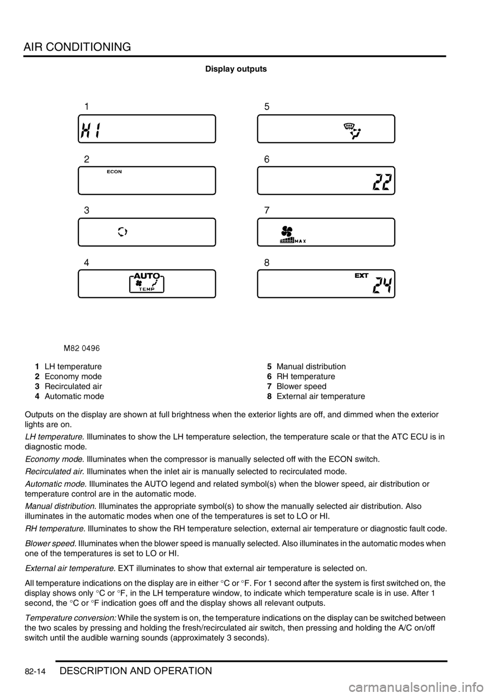
Display outputs
1LH temperature
2Economy mode
3Recirculated air
4Automatic mode5Manual distribution
6RH temperature
7Blower speed
8External air temperature
Outputs on the display are shown at full brightness when the exterior lights are off, and dimmed when the exterior
lights are on.
LH temperature. Illuminates to show the LH temperature selection, the temperature scale or that the ATC ECU is in
diagnostic mode.
Economy mode. Illuminates when the compressor is manually selected off with the ECON switch.
Recirculated air. Illuminates when the inlet air is manually selected to recirculated mode.
Automatic mode. Illuminates the AUTO legend and related symbol(s) when the blower speed, air distribution or
temperature control are in the automatic mode.
Manual distribution. Illuminates the appropriate symbol(s) to show the manually selected air distribution. Also
illuminates in the automatic modes when one of the temperatures is set to LO or HI.
RH temperature. Illuminates to show the RH temperature selection, external air temperature or diagnostic fault code.
Blower speed. Illuminates when the blower speed is manually selected. Also illuminates in the automatic modes when
one of the temperatures is set to LO or HI.
External air temperature. EXT illuminates to show that external air temperature is selected on.
All temperature indications on the display are in either °C or °F. For 1 second after the system is first switched on, the
display shows only °C or °F, in the LH temperature window, to indicate which temperature scale is in use. After 1
second, the °C or °F indication goes off and the display shows all relevant outputs.
Temperature conversion: While the system is on, the temperature indications on the display can be switched between
the two scales by pressing and holding the fresh/recirculated air switch, then pressing and holding the A/C on/off
switch until the audible warning sounds (approximately 3 seconds).