1999 DODGE RAM parking brake
[x] Cancel search: parking brakePage 859 of 1691

junction block. See WIRING DIAGRAMS.
4) Turn ignition off. Disconnect negative battery cable.
Disconnect parking brake switch connector. Switch is located at base
of parking brake lever. Ensure parking brake lever is released. Check
continuity between ground and parking brake switch terminal. If
continuity does not exist, go to next step. If continuity exists,
adjust or replace parking brake switch.
5) Ensure parking brake switch is still disconnected. Turn
ignition off. Remove instrument cluster. See INSTRUMENT CLUSTER under
REMOVAL & INSTALLATION. Check continuity between ground and park brake
switch connector. If continuity does not exist, go to next step. If
continuity exists, repair short to ground between instrument cluster
and park brake switch.
6) Check continuity between park brake switch connector and
instrument cluster connector C1, terminal No. 3 (White/Pink wire on
Ram Van and Ram Wagon; White/Light Green wire on Ram Pickup). See
Fig. 1. If continuity does not exist, repair open circuit. See WIRING
DIAGRAMS. If continuity exists, see PRELIMINARY DIAGNOSIS under SELF-
DIAGNOSTIC SYSTEM.
FOUR WHEEL DRIVE (4WD) LIGHT INOPERATIVE (RAM PICKUP)
1) Remove and inspect fuse No. 17 (10-amp) in junction block\
.
Junction block is located at left end cover of instrument panel. If
fuse is okay, go to next step. If fuse is blown, locate and repair
cause of blown fuse. Install new fuse and recheck system operation.
2) Turn ignition on. Measure voltage between ground and power
side of fuse No. 17. If battery voltage is present, go to next step.
If battery voltage is not present, locate and repair open circuit
between ignition switch and junction block.
3) Turn ignition off. Disconnect negative battery cable.
Disconnect 4WD switch connector. 4WD switch connector is located at
right side of front axle. Check continuity between 4WD switch
connector Black wire and ground. If continuity does not exist, repair
open Black wire between 4WD switch and ground. If continuity exists,
go to next step.
4) Reconnect battery cable. Turn ignition on. Install jumper
wire between 4WD switch connector terminals. 4WD light should
illuminate. If light illuminates, replace 4WD switch. If light does
not illuminate, go to next step.
5) Turn ignition off. Disconnect negative battery cable.
Ensure 4WD switch is still disconnected. Remove instrument cluster.
See INSTRUMENT CLUSTER under REMOVAL & INSTALLATION. Check continuity
between ground and instrument cluster connector C2 terminal No. 10
(Gray wire). See Fig. 1. If continuity does not exist, go to next
step. If continuity exists, repair short to ground in wire between
instrument cluster and 4WD switch.
6) Check continuity of wire between 4WD switch connector and
terminal No. 10 at instrument cluster connector C2. If continuity does
not exist, repair open wire. If continuity exists, replace bulb.
LOW WASHER FLUID LIGHT INOPERATIVE
1) Remove and inspect fuse No. 17 (10-amp) on Ram Pickup or
fuse No. 11 (10-amp) on Ram Van and Ram Wagon in junction block.
Junction block is located at left end cover of instrument panel. If
fuse is okay, go to next step. If fuse is blown, locate and repair
cause of blown fuse. Install new fuse and recheck system operation.
2) Turn ignition on. Measure voltage between ground and power
side of fuse No. 14 (10-amp) on Ram Pickup or fuse No. 11 (10-amp) o\
n
Ram Van and Ram Wagon. If battery voltage is present, go to next step.
If battery voltage is not present, locate and repair open circuit
between ignition switch and junction block.
Page 862 of 1691

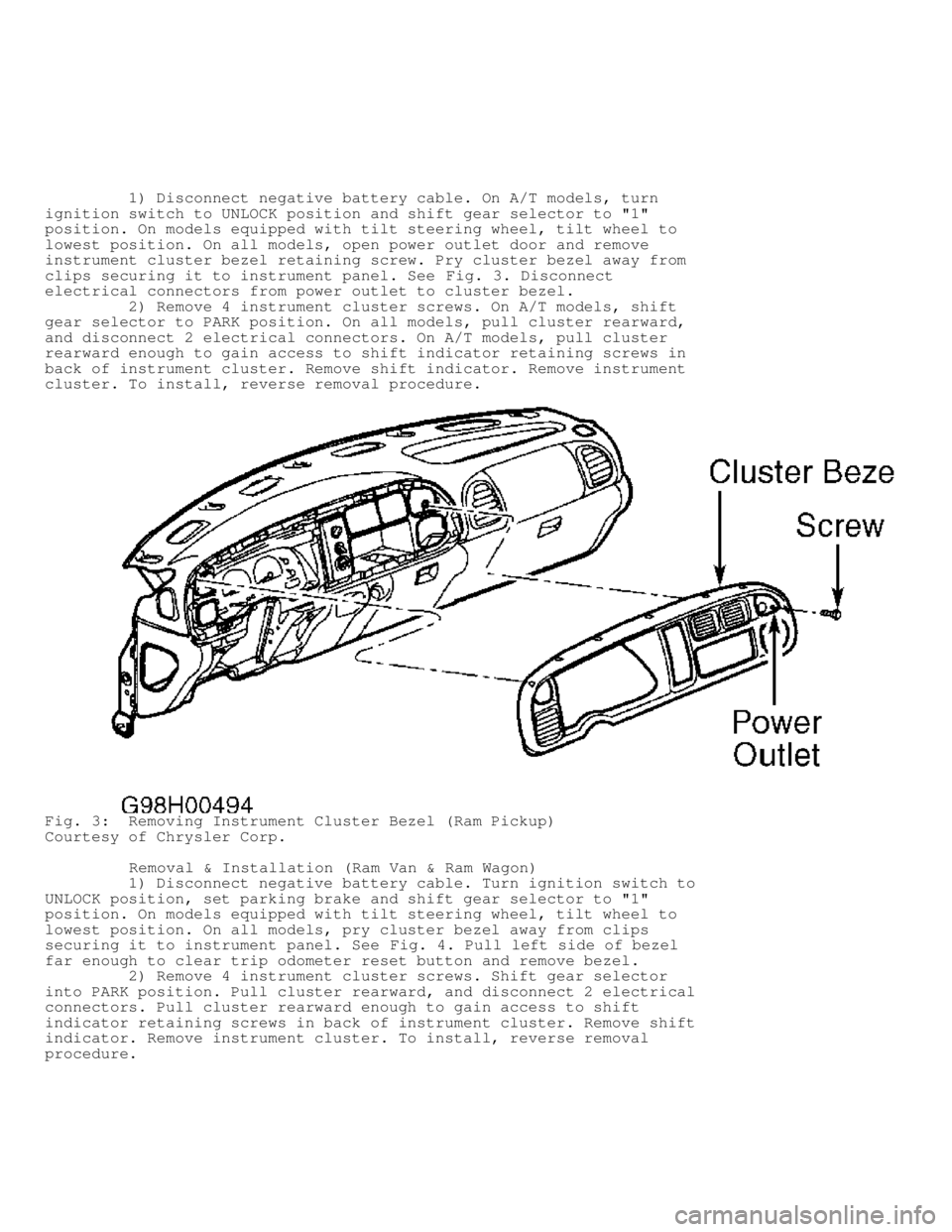
1) Disconnect negative battery cable. On A/T models, turn
ignition switch to UNLOCK position and shift gear selector to "1"
position. On models equipped with tilt steering wheel, tilt wheel to
lowest position. On all models, open power outlet door and remove
instrument cluster bezel retaining screw. Pry cluster bezel away from
clips securing it to instrument panel. See Fig. 3. Disconnect
electrical connectors from power outlet to cluster bezel.
2) Remove 4 instrument cluster screws. On A/T models, shift
gear selector to PARK position. On all models, pull cluster rearward,
and disconnect 2 electrical connectors. On A/T models, pull cluster
rearward enough to gain access to shift indicator retaining screws in
back of instrument cluster. Remove shift indicator. Remove instrument
cluster. To install, reverse removal procedure.
Fig. 3: Removing Instrument Cluster Bezel (Ram Pickup)
Courtesy of Chrysler Corp.
Removal & Installation (Ram Van & Ram Wagon)
1) Disconnect negative battery cable. Turn ignition switch to
UNLOCK position, set parking brake and shift gear selector to "1"
position. On models equipped with tilt steering wheel, tilt wheel to
lowest position. On all models, pry cluster bezel away from clips
securing it to instrument panel. See Fig. 4. Pull left side of bezel
far enough to clear trip odometer reset button and remove bezel.
2) Remove 4 instrument cluster screws. Shift gear selector
into PARK position. Pull cluster rearward, and disconnect 2 electrical
connectors. Pull cluster rearward enough to gain access to shift
indicator retaining screws in back of instrument cluster. Remove shift
indicator. Remove instrument cluster. To install, reverse removal
procedure.
Page 899 of 1691

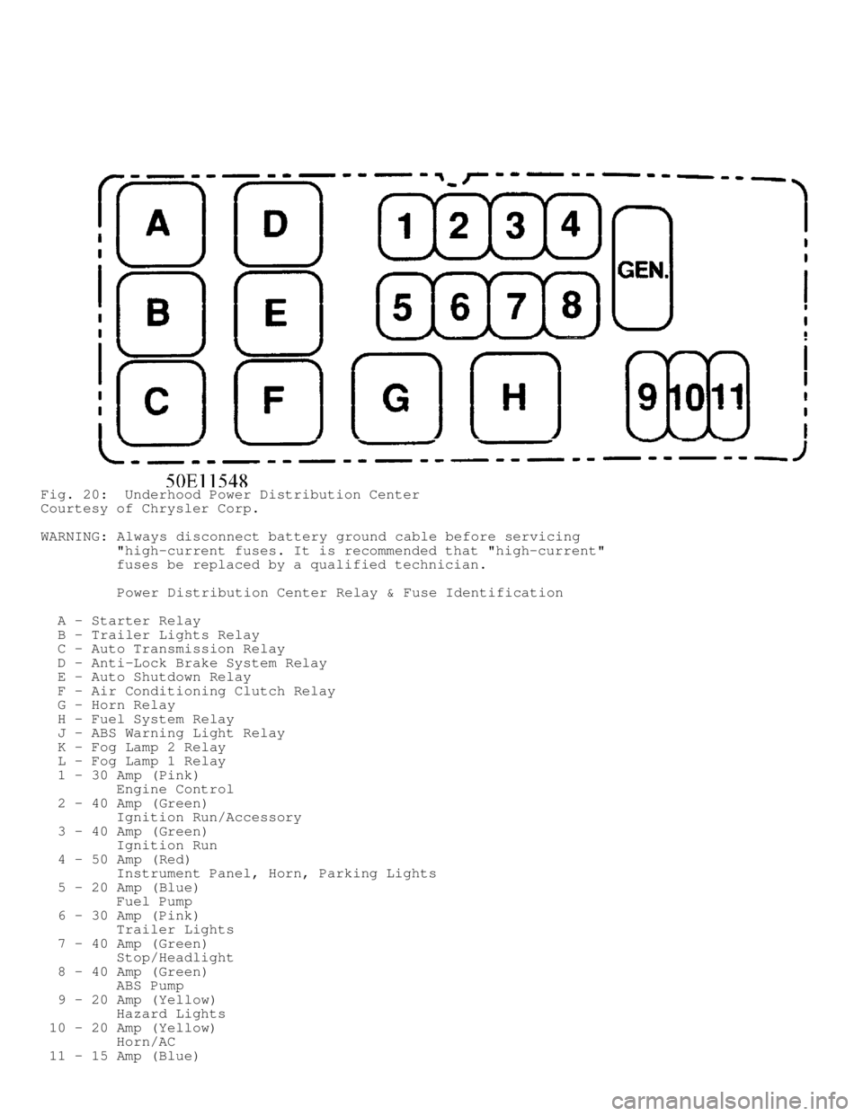
Fig. 20: Underhood Power Distribution Center
Courtesy of Chrysler Corp.
WARNING: Always disconnect battery ground cable before servicing
"high-current fuses. It is recommended that "high-current"
fuses be replaced by a qualified technician.
Power Distribution Center Relay & Fuse Identification
A - Starter Relay
B - Trailer Lights Relay
C - Auto Transmission Relay
D - Anti-Lock Brake System Relay
E - Auto Shutdown Relay
F - Air Conditioning Clutch Relay
G - Horn Relay
H - Fuel System Relay
J - ABS Warning Light Relay
K - Fog Lamp 2 Relay
L - Fog Lamp 1 Relay
1 - 30 Amp (Pink)
Engine Control
2 - 40 Amp (Green)
Ignition Run/Accessory
3 - 40 Amp (Green)
Ignition Run
4 - 50 Amp (Red)
Instrument Panel, Horn, Parking Lights
5 - 20 Amp (Blue)
Fuel Pump
6 - 30 Amp (Pink)
Trailer Lights
7 - 40 Amp (Green)
Stop/Headlight
8 - 40 Amp (Green)
ABS Pump
9 - 20 Amp (Yellow)
Hazard Lights
10 - 20 Amp (Yellow)
Horn/AC
11 - 15 Amp (Blue)
Page 926 of 1691

Removal (A/T Models)
Raise and support vehicle. Disconnect electrical connector
from park/neutral switch. Park/neutral switch is located on side of
transmission case, near shift linkage. Unscrew park/neutral switch
from transmission case. Remove seal ring from park/neutral switch.
Installation
1) Apply parking brake. Place shift lever in Park and
Neutral. Ensure park/neutral switch operating levers in transmission
are centered in the park/neutral switch opening on transmission case.
2) Using NEW seal ring, install park/neutral switch. Tighten
park/neutral switch to specification. See TORQUE SPECIFICATIONS.
Install electrical connector. Add ATF as necessary.
ACCELERATOR PEDAL POSITION SENSOR (APPS)
NOTE: APPS is replaced as assembly, including lever, brackets, and
sensor.
Removal
1) Disconnect negative battery cables. Remove cable cover.
Using finger pressure only, disconnect end of speed control servo
cable from throttle lever pin by pulling forward on connector while
holding lever rearward. Using 2 small screwdrivers, pry throttle cable
connector socket from throttle lever ball.
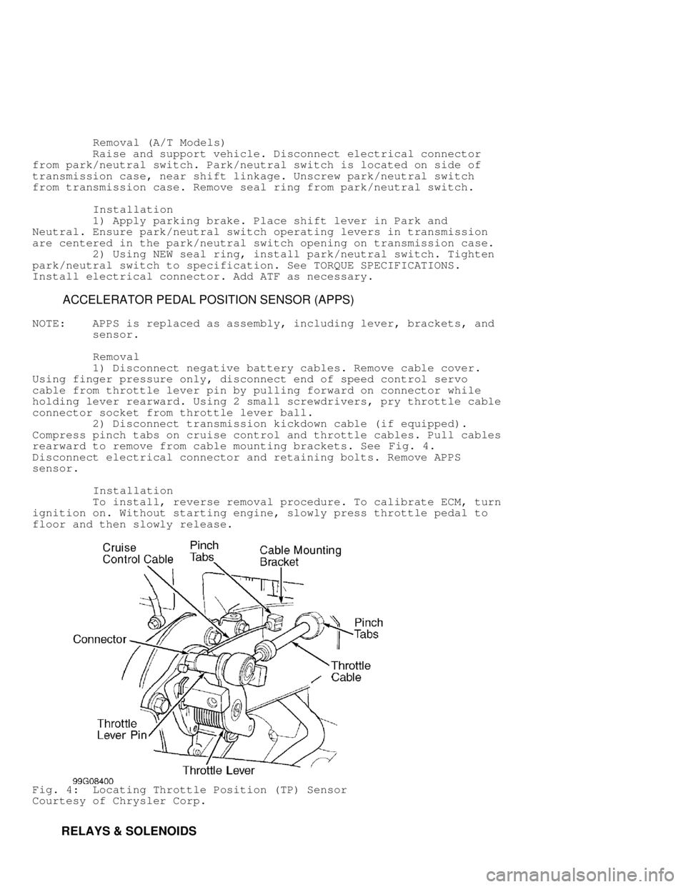
2) Disconnect transmission kickdown cable (if equipped).
Compress pinch tabs on cruise control and throttle cables. Pull cables
rearward to remove from cable mounting brackets. See Fig. 4.
Disconnect electrical connector and retaining bolts. Remove APPS
sensor.
Installation
To install, reverse removal procedure. To calibrate ECM, turn
ignition on. Without starting engine, slowly press throttle pedal to
floor and then slowly release.
Fig. 4: Locating Throttle Position (TP) Sensor
Courtesy of Chrysler Corp.
RELAYS & SOLENOIDS
Page 930 of 1691

FUEL LINE BLEEDING
NOTE: Fuel line bleeding is necessary if fuel injection pump is
replaced, fuel filter/water separator is not filled with
diesel fuel before installing or vehicle ran out off fuel.
Bleed high-pressure fuel lines if connections are loosened or
replaced. If engine has not been operated for an extended
time, bleed fuel lines before next initial engine start-up.
WARNING: DO NOT bleed fuel lines on a hot engine, as high exhaust
temperatures may cause a fire. Carefully bleed fuel lines, as
fuel is under extremely high pressure and could penetrate
skin. Use safety goggles and protective clothing when
bleeding fuel lines.
1) Loosen banjo bolt holding low-pressure fuel supply line to
side of fuel injection pump. Wrap a towel around banjo fitting to
catch fuel. Crank engine quickly and release key before engine starts.
This will operate fuel transfer pump for about 25 seconds.
2) If fuel is not present at fuel supply line after 25
seconds, turn ignition off. Repeat engine crank procedure until fuel
is present at fuel supply line. Tighten banjo bolt at fuel supply line
to specification. See TORQUE SPECIFICATIONS.
CAUTION: Ensure parking brake is applied and transmission is in
Neutral before bleeding fuel injection pump or high-pressure
fuel lines. DO NOT operate starter for more than 30 seconds
when bleeding fuel injection pump or high-pressure fuel
lines. Allow 2-minute intervals between starter operations.
3) To bleed air from fuel injection pump, ensure parking
brake is applied and transmission is in Neutral, as engine may start
when operating starter to bleed air from fuel injection pump. Operate
starter for 30 seconds to bleed any trapped air in fuel injection
pump.
4) To bleed high-pressure fuel lines, ensure parking brake is
applied and transmission is in Neutral, as engine may start when
operating starter to bleed high-pressure fuel lines. Loosen high-
pressure fuel line nut at fuel injector.
5) Operate starter until steady fuel flow exists at high-
pressure fuel line. Tighten high-pressure fuel line nut to
specification. See TORQUE SPECIFICATIONS. Start engine. Repeat
procedure on each high-pressure fuel line until engine operates
smoothly.
FUEL FILTER/WATER SEPARATOR & WATER-IN-FUEL SENSOR
NOTE: Vehicle also contains an in-tank fuel filter located on
bottom of fuel tank module. For servicing procedure, see FUEL
TANK MODULE & IN-TANK FUEL FILTER under FUEL SYSTEM.
NOTE: When fuel filter/water separator is being replaced,
manufacturer recommends cleaning the pre-filter. See FUEL
HEATER under FUEL SYSTEM for servicing of pre-filter.
Removal
1) Ensure engine is off. Place drain pan below drain tube at
fuel filter/water separator. See Fig. 3. Rotate handle on drain valve
forward, toward front of vehicle to DRAIN position. Drain valve is
located near top of fuel filter/water separator. See Fig. 3. Once fuel
is drained from fuel filter/water separator, rotate handle on drain
valve back to CLOSE position.
Page 945 of 1691

bracket. Ensure alignment tab on brake switch aligns with opening on
mounting bracket.
CAUTION: When adjusting brake switch, DO NOT pull brake pedal back
toward brake switch with excessive pressure, or brake switch
may be damaged.
3) When brake switch is fully installed in mounting bracket,
rotate brake switch clockwise approximately 30 degrees. To ensure
proper brake switch adjustment, gently pull brake pedal back toward
brake switch as far as possible. DO NOT apply excessive pressure on
brake pedal and brake switch.
Removal (Ram Van & Ram Wagon)
1) Brake switch is located near top of brake pedal. Remove
lower steering column cover. Remove data link connector, hood release
lever and parking brake lever from lower instrument panel cover.
2) Remove lower instrument panel cover for access to brake
switch. Depress and hold brake pedal downward. Rotate brake switch
counterclockwise approximately 1/16 turn to so locking collar on brake
switch aligns with opening on mounting bracket. Pull brake switch
rearward from mounting bracket. Disconnect electrical connector from
brake switch.
NOTE: Before installing brake switch, plunger on brake switch must
be pulled outward to fully extended position and then pushed
inward 4 detent positions to ensure proper brake switch
adjustment.
Installation
1) Pull plunger on brake switch outward to the fully extended
position. Push plunger on brake switch inward 4 detent positions. The
brake switch will click at each detent position when pushing plunger
inward.
2) Install electrical connector on brake switch. Depress
brake pedal as far as possible. Install brake switch in mounting
bracket. Ensure locking collar on brake switch aligns with opening on
mounting bracket.
CAUTION: When adjusting brake switch, DO NOT pull brake pedal back
toward brake switch with excessive pressure, or brake switch
may be damaged.
3) When brake switch is fully installed in mounting bracket,
rotate brake switch clockwise approximately 1/16 turn. To ensure
proper brake switch adjustment, gently pull brake pedal back toward
brake switch as far as possible. DO NOT apply excessive pressure on
brake pedal and brake switch.
CAMSHAFT POSITION SENSOR
Removal & Installation
See CAMSHAFT POSITION SENSOR under IGNITION SYSTEM.
CRANKSHAFT POSITION SENSOR
Removal & Installation
See CRANKSHAFT POSITION SENSOR under IGNITION SYSTEM.
DOWNSTREAM OXYGEN SENSOR
NOTE: Downstream oxygen sensor may also be referred to as post
-catalyst oxygen sensor.
Page 952 of 1691

NOTE: Park/neutral switch may also be referred to as park/neutral
position switch.
Removal (A/T Models)
Raise and support vehicle. Disconnect 3-pin electrical
connector from park/neutral switch. Park/neutral switch is located on
driver's side of transmission case, near shift linkage. See Fig. 10.
Unscrew park/neutral switch from transmission case. Remove seal ring
from park/neutral switch.
Installation
1) Apply parking brake. Place shift lever in Neutral. Ensure
park/neutral switch operating levers in transmission are centered in
the park/neutral switch opening on transmission case.
2) Using NEW seal ring, install park/neutral switch. Tighten
park/neutral switch to specification. See TORQUE SPECIFICATIONS.
Install electrical connector. Add Mopar Plus 7176 ATF as necessary.
POWER STEERING PRESSURE SWITCH
Removal & Installation (Dakota 2.5L)
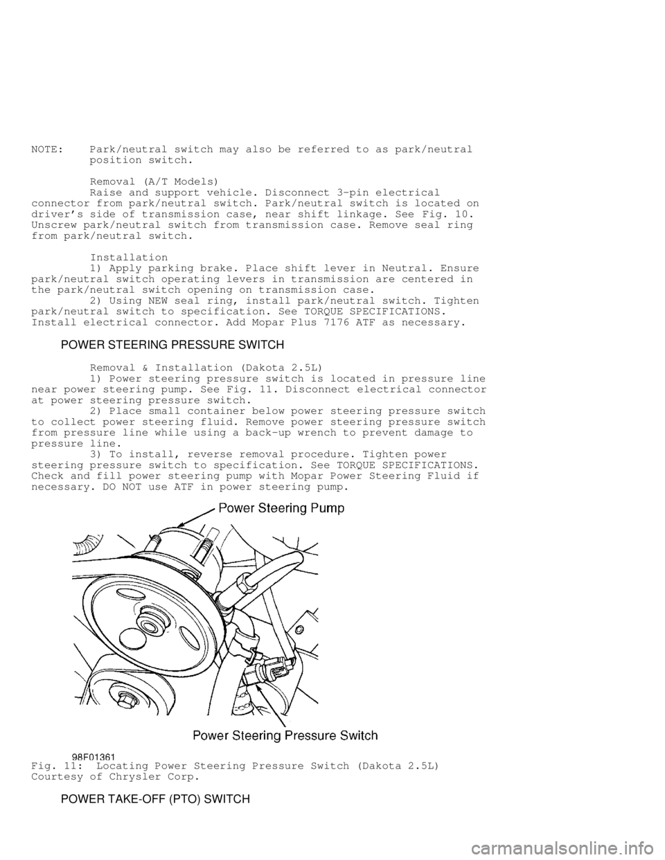
1) Power steering pressure switch is located in pressure line
near power steering pump. See Fig. 11. Disconnect electrical connector
at power steering pressure switch.
2) Place small container below power steering pressure switch
to collect power steering fluid. Remove power steering pressure switch
from pressure line while using a back-up wrench to prevent damage to
pressure line.
3) To install, reverse removal procedure. Tighten power
steering pressure switch to specification. See TORQUE SPECIFICATIONS.
Check and fill power steering pump with Mopar Power Steering Fluid if
necessary. DO NOT use ATF in power steering pump.
Fig. 11: Locating Power Steering Pressure Switch (Dakota 2.5L)
Courtesy of Chrysler Corp.
POWER TAKE-OFF (PTO) SWITCH
Page 1210 of 1691

ON-VEHICLE TESTING
CAUTION: When battery is disconnected, vehicle computer and memory
systems may lose memory data. Driveability problems may exist
until computer systems have completed a relearn cycle. See
COMPUTER RELEARN PROCEDURES article in GENERAL INFORMATION
before disconnecting battery.
DISABLING/ENABLING IGNITION & FUEL SYSTEMS
WARNING: To prevent engine from starting while performing tests,
always disable ignition and fuel systems.
Disabling Ignition & Fuel Systems
Remove Automatic Shutdown Relay (ASD) located in Power
Distribution Center (PDC). Refer to PDC cover for proper relay
location. PDC is located in engine compartment. On 5.9L diesel
engines, also disconnect fuel shutdown solenoid connector. Solenoid is
located behind upper intake manifold. See appropriate SYSTEM &
COMPONENT TESTING article in ENGINE PERFORMANCE section.
Enabling Ignition & Fuel Systems
When testing and/or repairs have been completed, verify
battery condition. Recharge battery as necessary, after starter tests
have been completed. Disconnect all test equipment. Install ASD relay.
On 5.9L diesel engines, reconnect fuel shutdown relay connector. On
all models, start engine several times to verify malfunction has been
corrected.
CRANKING TEST
NOTE: Ensure engine is at normal operating temperature. High
viscosity oil, extreme cold temperatures, or tight engine
will increase amperage draw.
1) Using a battery load tester, connect positive and negative
leads to battery. Connect inductive ammeter pick-up to positive
battery cable. Disable ignition and fuel systems. See
DISABLING/ENABLING IGNITION & FUEL SYSTEMS.
2) Ensure all lights and accessories are off. Place A/T in
Park position or M/T in Neutral position. Apply parking brake. Crank
engine and observe voltmeter reading. If voltage is more than 9.6
volts and cranking amperage draw is more than specified amps, proceed
to CIRCUIT RESISTANCE TESTS. See STARTER SPECIFICATIONS - CARS or
STARTER SPECIFICATIONS - TRUCKS.
3) If voltage is 12.5 volts or more and cranking amperage
draw is less than specified, check starter circuit components in the
following order:
starter solenoid, starter relay, starter relay circuit, park/neutral
position switch or transmission range sensor (A/T), clutch pedal
position switch (M/T), ignition switch, wiring harness and
connections.
CIRCUIT RESISTANCE TESTS
NOTE: If excessive resistance is not found in circuits being
tested, remove starter and proceed to BENCH TESTING.
Battery Connection Resistance Test
1) Disable vehicle ignition and fuel systems. See
DISABLING/ENABLING IGNITION & FUEL SYSTEMS. A voltmeter accurate to
one tenth of a volt will be needed for the following tests.