1999 DODGE NEON Head
[x] Cancel search: HeadPage 9 of 1200
DISCONNECT CABLE CLAMPS AS FOLLOWS:
²Disconnect BLACK cable clamp from engine
ground on disabled vehicle.
²When using a Booster vehicle, disconnect
BLACK cable clamp from battery negative terminal.
Disconnect RED cable clamp from battery positive
terminal.
²Disconnect RED cable clamp from battery posi-
tive terminal on disabled vehicle.
TOWING RECOMMENDATIONS
WARNING: DO NOT ALLOW TOWING ATTACH-
MENT DEVICES TO CONTACT THE FUEL TANK OR
LINES, FUEL LEAK CAN RESULT. DO NOT LIFT OR
TOW VEHICLE BY FRONT OR REAR BUMPER, OR
BUMPER ENERGY ABSORBER UNITS. DO NOT
VENTURE UNDER A LIFTED VEHICLE IF NOT SUP-
PORTED PROPERLY ON SAFETY STANDS. DO NOT
ALLOW PASSENGERS TO RIDE IN A TOWED VEHI-
CLE. USE A SAFETY CHAIN THAT IS INDEPENDENT
FROM THE TOWING ATTACHMENT DEVICE.
CAUTION: Do not damage brake lines, exhaust
system, shock absorbers, sway bars, or any other
under vehicle components when attaching towing
device to vehicle. Do not attach towing device to
front or rear suspension components. Do not
secure vehicle to towing device by the use of front
or rear suspension or steering components.
Remove or secure loose or protruding objects from
a damaged vehicle before towing. Refer to state and
local rules and regulations before towing a vehicle.
Do not allow weight of towed vehicle to bear on
lower fascia, air dams, or spoilers.
RECOMMENDED TOWING EQUIPMENT
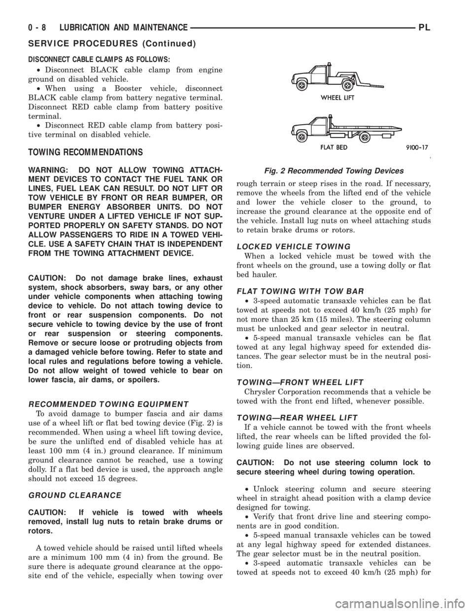
To avoid damage to bumper fascia and air dams
use of a wheel lift or flat bed towing device (Fig. 2) is
recommended. When using a wheel lift towing device,
be sure the unlifted end of disabled vehicle has at
least 100 mm (4 in.) ground clearance. If minimum
ground clearance cannot be reached, use a towing
dolly. If a flat bed device is used, the approach angle
should not exceed 15 degrees.
GROUND CLEARANCE
CAUTION: If vehicle is towed with wheels
removed, install lug nuts to retain brake drums or
rotors.
A towed vehicle should be raised until lifted wheels
are a minimum 100 mm (4 in) from the ground. Be
sure there is adequate ground clearance at the oppo-
site end of the vehicle, especially when towing overrough terrain or steep rises in the road. If necessary,
remove the wheels from the lifted end of the vehicle
and lower the vehicle closer to the ground, to
increase the ground clearance at the opposite end of
the vehicle. Install lug nuts on wheel attaching studs
to retain brake drums or rotors.
LOCKED VEHICLE TOWING
When a locked vehicle must be towed with the
front wheels on the ground, use a towing dolly or flat
bed hauler.
FLAT TOWING WITH TOW BAR
²3-speed automatic transaxle vehicles can be flat
towed at speeds not to exceed 40 km/h (25 mph) for
not more than 25 km (15 miles). The steering column
must be unlocked and gear selector in neutral.
²5-speed manual transaxle vehicles can be flat
towed at any legal highway speed for extended dis-
tances. The gear selector must be in the neutral posi-
tion.
TOWINGÐFRONT WHEEL LIFT
Chrysler Corporation recommends that a vehicle be
towed with the front end lifted, whenever possible.
TOWINGÐREAR WHEEL LIFT
If a vehicle cannot be towed with the front wheels
lifted, the rear wheels can be lifted provided the fol-
lowing guide lines are observed.
CAUTION: Do not use steering column lock to
secure steering wheel during towing operation.
²Unlock steering column and secure steering
wheel in straight ahead position with a clamp device
designed for towing.
²Verify that front drive line and steering compo-
nents are in good condition.
²5-speed manual transaxle vehicles can be towed
at any legal highway speed for extended distances.
The gear selector must be in the neutral position.
²3-speed automatic transaxle vehicles can be
towed at speeds not to exceed 40 km/h (25 mph) for
Fig. 2 Recommended Towing Devices
0 - 8 LUBRICATION AND MAINTENANCEPL
SERVICE PROCEDURES (Continued)
Page 13 of 1200
COMPETITION PACKAGE ALIGNMENT
If a vehicle is equipped with the optional competi-
tion package, (S/C ACR) the front wheel camber is
adjustable.
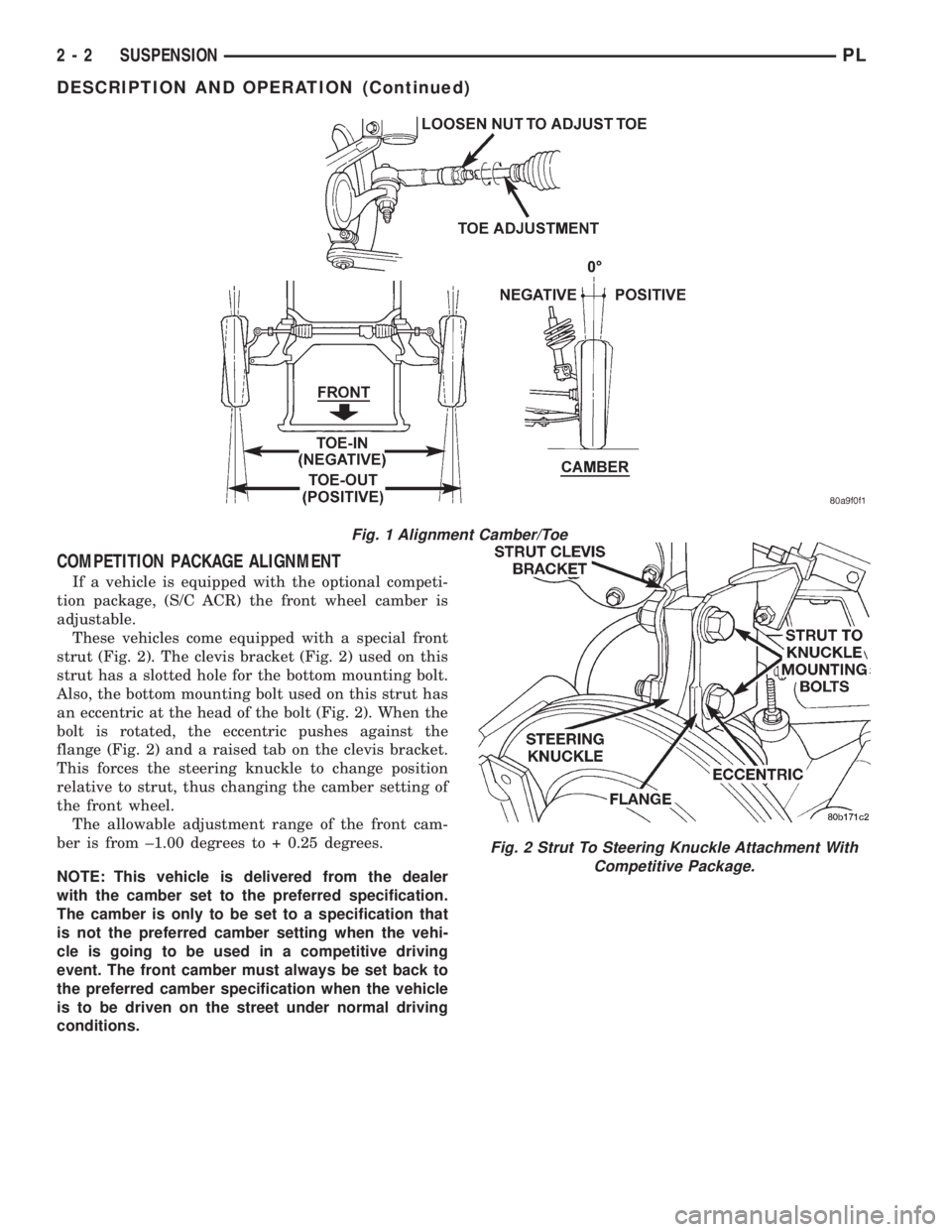
These vehicles come equipped with a special front
strut (Fig. 2). The clevis bracket (Fig. 2) used on this
strut has a slotted hole for the bottom mounting bolt.
Also, the bottom mounting bolt used on this strut has
an eccentric at the head of the bolt (Fig. 2). When the
bolt is rotated, the eccentric pushes against the
flange (Fig. 2) and a raised tab on the clevis bracket.
This forces the steering knuckle to change position
relative to strut, thus changing the camber setting of
the front wheel.
The allowable adjustment range of the front cam-
ber is from ±1.00 degrees to + 0.25 degrees.
NOTE: This vehicle is delivered from the dealer
with the camber set to the preferred specification.
The camber is only to be set to a specification that
is not the preferred camber setting when the vehi-
cle is going to be used in a competitive driving
event. The front camber must always be set back to
the preferred camber specification when the vehicle
is to be driven on the street under normal driving
conditions.
Fig. 1 Alignment Camber/Toe
Fig. 2 Strut To Steering Knuckle Attachment With
Competitive Package.
2 - 2 SUSPENSIONPL
DESCRIPTION AND OPERATION (Continued)
Page 18 of 1200
COMPETITION PACKAGE ALIGNMENT PROCEDURE
If a vehicle is equipped with the optional competi-
tion package, (S/C ACR) the front wheel camber is
adjustable.
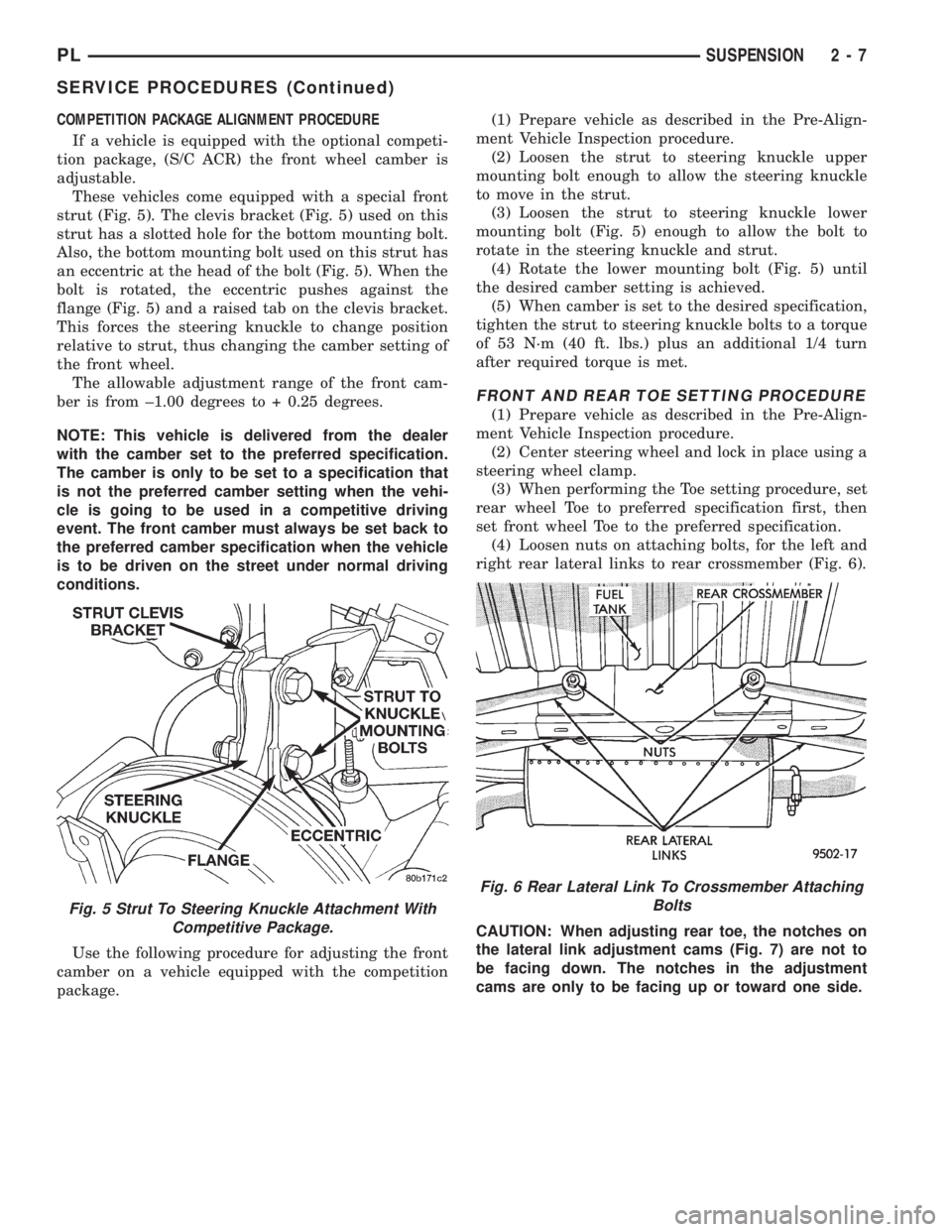
These vehicles come equipped with a special front
strut (Fig. 5). The clevis bracket (Fig. 5) used on this
strut has a slotted hole for the bottom mounting bolt.
Also, the bottom mounting bolt used on this strut has
an eccentric at the head of the bolt (Fig. 5). When the
bolt is rotated, the eccentric pushes against the
flange (Fig. 5) and a raised tab on the clevis bracket.
This forces the steering knuckle to change position
relative to strut, thus changing the camber setting of
the front wheel.
The allowable adjustment range of the front cam-
ber is from ±1.00 degrees to + 0.25 degrees.
NOTE: This vehicle is delivered from the dealer
with the camber set to the preferred specification.
The camber is only to be set to a specification that
is not the preferred camber setting when the vehi-
cle is going to be used in a competitive driving
event. The front camber must always be set back to
the preferred camber specification when the vehicle
is to be driven on the street under normal driving
conditions.
Use the following procedure for adjusting the front
camber on a vehicle equipped with the competition
package.(1) Prepare vehicle as described in the Pre-Align-
ment Vehicle Inspection procedure.
(2) Loosen the strut to steering knuckle upper
mounting bolt enough to allow the steering knuckle
to move in the strut.
(3) Loosen the strut to steering knuckle lower
mounting bolt (Fig. 5) enough to allow the bolt to
rotate in the steering knuckle and strut.
(4) Rotate the lower mounting bolt (Fig. 5) until
the desired camber setting is achieved.
(5) When camber is set to the desired specification,
tighten the strut to steering knuckle bolts to a torque
of 53 N´m (40 ft. lbs.) plus an additional 1/4 turn
after required torque is met.
FRONT AND REAR TOE SETTING PROCEDURE
(1) Prepare vehicle as described in the Pre-Align-
ment Vehicle Inspection procedure.
(2) Center steering wheel and lock in place using a
steering wheel clamp.
(3) When performing the Toe setting procedure, set
rear wheel Toe to preferred specification first, then
set front wheel Toe to the preferred specification.
(4) Loosen nuts on attaching bolts, for the left and
right rear lateral links to rear crossmember (Fig. 6).
CAUTION: When adjusting rear toe, the notches on
the lateral link adjustment cams (Fig. 7) are not to
be facing down. The notches in the adjustment
cams are only to be facing up or toward one side.
Fig. 5 Strut To Steering Knuckle Attachment With
Competitive Package.
Fig. 6 Rear Lateral Link To Crossmember Attaching
Bolts
PLSUSPENSION 2 - 7
SERVICE PROCEDURES (Continued)
Page 40 of 1200
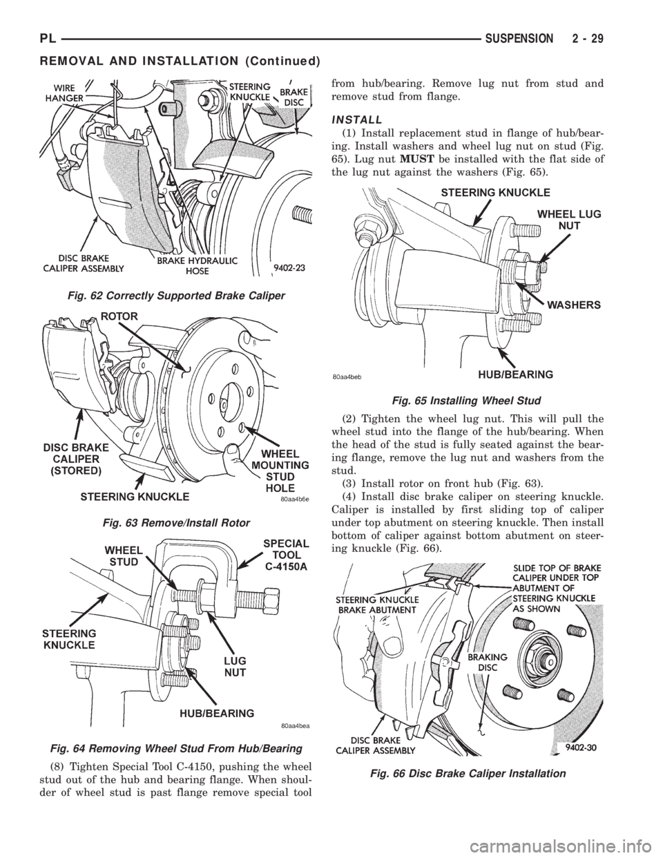
(8) Tighten Special Tool C-4150, pushing the wheel
stud out of the hub and bearing flange. When shoul-
der of wheel stud is past flange remove special toolfrom hub/bearing. Remove lug nut from stud and
remove stud from flange.
INSTALL
(1) Install replacement stud in flange of hub/bear-
ing. Install washers and wheel lug nut on stud (Fig.
65). Lug nutMUSTbe installed with the flat side of
the lug nut against the washers (Fig. 65).
(2) Tighten the wheel lug nut. This will pull the
wheel stud into the flange of the hub/bearing. When
the head of the stud is fully seated against the bear-
ing flange, remove the lug nut and washers from the
stud.
(3) Install rotor on front hub (Fig. 63).
(4) Install disc brake caliper on steering knuckle.
Caliper is installed by first sliding top of caliper
under top abutment on steering knuckle. Then install
bottom of caliper against bottom abutment on steer-
ing knuckle (Fig. 66).
Fig. 62 Correctly Supported Brake Caliper
Fig. 63 Remove/Install Rotor
Fig. 64 Removing Wheel Stud From Hub/Bearing
Fig. 65 Installing Wheel Stud
Fig. 66 Disc Brake Caliper Installation
PLSUSPENSION 2 - 29
REMOVAL AND INSTALLATION (Continued)
Page 57 of 1200

sequence until all nuts are torqued to half specifica-
tion. Then repeat the tightening sequence to the full
specified torque of 129 N´m (95 ft. lbs.).
(5) Lower the vehicle to the ground.
(6) With suspension supporting the full weight of
the vehicle, securely tighten the stabilizer bar
retainer to frame rail attaching bolts (Fig. 11).
KNUCKLE
REMOVE
(1) Raise vehicle on jackstands or centered on a
frame contact type hoist. See Hoisting in the Lubri-
cation and Maintenance section of this manual, for
the required lifting procedure to be used for this
vehicle.
(2) Remove the rear wheel and tire.
(3) If vehicle is equipped with rear disc brakes,
remove the rear caliper from the adapter. Refer to
Rear Disk Brakes in Group 5 Brakes of this Service
manual for required caliper removal procedure. After
removing the caliper, store the caliper by hanging it
from frame of the vehicle (Fig. 14). Do not let weight
of rear caliper hang from flexible brake hose.
(4) If vehicle is equipped with rear disc brakes,
remove rotor from hub. If vehicle is equipped with
rear drum brakes, remove brake drum from hub.
(5) If vehicle is equipped with ABS brakes, remove
wheel speed sensor from rear disc brake adapter
(Fig. 15).
(6) Remove rear hub/bearing retaining nut (Fig.
16). Then remove the hub/bearing from the knuckle.(7) If vehicle is equipped with rear drum brakes
remove the 4 bolts (Fig. 17) attaching rear brake sup-
port plate to knuckle. Then remove brake support
plate, brake shoes and wheel cylinder as an assembly
from rear knuckle (Fig. 17).It is not necessary to
remove brake flex hose from wheel cylinder
when removing support plate.Brake support
plate when removed, must be supported in same
manner as caliper assembly.
(8) On vehicles equipped with rear disc brakes,
remove the 4 bolts attaching disc brake adapter to
rear knuckle (Fig. 18). Then remove the adapter,
rotor shield, park brake shoes and park brake cable
as an assembly from knuckle.
CAUTION: The knuckle to strut assembly attaching
bolts are serrated and must not be turned during
removal. Loosen and remove nuts while holding
bolts stationary in knuckle.
Fig. 14 Storing Rear Caliper
Fig. 15 Speed Sensor Head Attachment To Disc
Brake Adapter
Fig. 16 Hub/ Bearing Retaining Nut
2 - 46 SUSPENSIONPL
REMOVAL AND INSTALLATION (Continued)
Page 59 of 1200

(4) Install tension strut bushing, tension strut
retainer and nut on tension strut (Fig. 21).When
installing tension strut retainers, the retainers
must be installed on tension strut, with cupped
side of retainer facing away from bushing and
knuckle (Fig. 21).
(5) Position a large adjustable wrench on flat of
tension strut to keep it from turning, (Fig. 22) and
then torque tension strut nut to 95 N´m (70 ft. lbs.).
(6) On vehicles equipped with rear drum brakes,
install rear brake support plate assembly onto the
knuckle (Fig. 17). Install the 4 bolts (Fig. 17) attach-
ing rear brake support plate to rear knuckle. Torque
attaching bolts to 68 N´m (50 ft. lbs.).
(7) On vehicles equipped with rear disc brakes,
install the disc brake adapter on knuckle (Fig. 18)
Install the 4 bolts attaching the disc brake adapter to
knuckle (Fig. 18). Torque attaching bolts to 68 N´m
(50 ft. lbs.).(8) If vehicle is equipped with ABS brakes, install
speed sensor head into rear brake support plate or
disc brake adapter (Fig. 15). Tighten wheel speed
sensor mounting bolt to a torque of 7 N´m (60 in.
lbs.).
CAUTION: The hub/bearing retaining nut must be
tightened to but must not exceed its required
torque specification. The proper torque specifica-
tion of the retaining nut is critical to the life of the
hub bearing.
(9) Install rear hub and bearing assembly on
knuckle. Install hub and bearing assembly retaining
nut (Fig. 16), and torque to 217 N´m (160 ft. lbs).
(10) If vehicle is equipped with rear disc brakes,
install rear braking disc on hub. If vehicle is
equipped with rear drum brakes, install the brake
drum on hub.
(11) If vehicle is equipped with rear disc brakes,
install rear braking disc on hub. Carefully install
rear brake caliper over braking disc and install on
adapter. Tighten the caliper assembly to adapter
mounting bolts to 22 N´m (192 in. lbs.). Refer to Rear
Disc Brakes in Group 5 Brakes in this service man-
ual for required caliper installation procedure.
(12) Install wheel and tire assembly on vehicle.
Tighten the wheel mounting stud nuts in proper
sequence until all nuts are torqued to half specifica-
tion. Then repeat the tightening sequence to the full
specified torque of 135 N´m (100 ft. lbs.).
(13) Lower vehicle.
(14) With suspension supporting total weight of
vehicle, and lateral links at correct curb height,
torque both lateral link attaching bolts to 95 N´m (70
ft. lbs.).
(15) Check and reset rear wheel TOE to specifica-
tions if required. Refer to Front And Rear Toe Setting
Procedure in the Wheel Alignment Check And
Adjustment section in this group of the service man-
ual for the required Toe setting procedure.
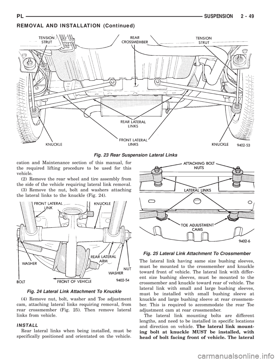
LATERAL LINKS
The rear suspension lateral links (Fig. 23) are only
serviced as complete assemblies. The isolator bush-
ings used in the lateral links are not serviced as sep-
arate components. The rear lateral link assemblies
are unique, having different size bushings to accom-
modate the rear Toe adjustment cams. The rearward
lateral links, must be installed with small bushing
sleeve at knuckle and large bushing sleeve at rear
crossmember. This is required to accommodate the
rear Toe adjustment cam.
REMOVE
(1) Raise vehicle on jackstands or centered on a
frame contact type hoist. See Hoisting in the Lubri-
Fig. 21 Tension Strut Bushings Installed On Tension
Strut
Fig. 22 Torquing Tension Strut Nut
2 - 48 SUSPENSIONPL
REMOVAL AND INSTALLATION (Continued)
Page 60 of 1200
cation and Maintenance section of this manual, for
the required lifting procedure to be used for this
vehicle.
(2) Remove the rear wheel and tire assembly from
the side of the vehicle requiring lateral link removal.
(3) Remove the nut, bolt and washers attaching
the lateral links to the knuckle (Fig. 24).
(4) Remove nut, bolt, washer and Toe adjustment
cam, attaching lateral links requiring removal, from
rear crossmember (Fig. 25). Then remove lateral
links from vehicle.
INSTALL
Rear lateral links when being installed, must be
specifically positioned and orientated on the vehicle.The lateral link having same size bushing sleeves,
must be mounted to the crossmember and knuckle
toward front of vehicle. The lateral link with differ-
ent size bushing sleeves, must be mounted to the
crossmember and knuckle toward rear of vehicle. The
lateral link with small and large bushing sleeves,
must be installed with small bushing sleeve at
knuckle and large bushing sleeve at rear crossmem-
ber. This is required to accommodate the rear Toe
adjustment cam at rear crossmember.
The lateral link mounting bolts are different
lengths, and need to be installed in specific locations
and direction on vehicle.The lateral link mount-
ing bolt at knuckle MUST be installed, with
head of bolt facing front of vehicle. The lateral
Fig. 23 Rear Suspension Lateral Links
Fig. 24 Lateral Link Attachment To Knuckle
Fig. 25 Lateral Link Attachment To Crossmember
PLSUSPENSION 2 - 49
REMOVAL AND INSTALLATION (Continued)
Page 61 of 1200
link mounting bolt at crossmember MUST be
installed, with head of bolt facing rear of vehi-
cle. The long attaching bolt must be used at
rear crossmember and short bolt used at
knuckle.
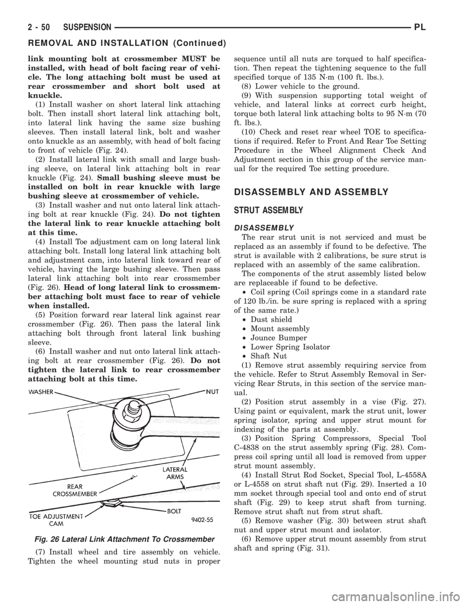
(1) Install washer on short lateral link attaching
bolt. Then install short lateral link attaching bolt,
into lateral link having the same size bushing
sleeves. Then install lateral link, bolt and washer
onto knuckle as an assembly, with head of bolt facing
to front of vehicle (Fig. 24).
(2) Install lateral link with small and large bush-
ing sleeve, on lateral link attaching bolt in rear
knuckle (Fig. 24).Small bushing sleeve must be
installed on bolt in rear knuckle with large
bushing sleeve at crossmember of vehicle.
(3) Install washer and nut onto lateral link attach-
ing bolt at rear knuckle (Fig. 24).Do not tighten
the lateral link to rear knuckle attaching bolt
at this time.
(4) Install Toe adjustment cam on long lateral link
attaching bolt. Install long lateral link attaching bolt
and adjustment cam, into lateral link toward rear of
vehicle, having the large bushing sleeve. Then pass
lateral link attaching bolt into rear crossmember
(Fig. 26).Head of long lateral link to crossmem-
ber attaching bolt must face to rear of vehicle
when installed.
(5) Position forward rear lateral link against rear
crossmember (Fig. 26). Then pass the lateral link
attaching bolt through front lateral link bushing
sleeve.
(6) Install washer and nut onto lateral link attach-
ing bolt at rear crossmember (Fig. 26).Do not
tighten the lateral link to rear crossmember
attaching bolt at this time.
(7) Install wheel and tire assembly on vehicle.
Tighten the wheel mounting stud nuts in propersequence until all nuts are torqued to half specifica-
tion. Then repeat the tightening sequence to the full
specified torque of 135 N´m (100 ft. lbs.).
(8) Lower vehicle to the ground.
(9) With suspension supporting total weight of
vehicle, and lateral links at correct curb height,
torque both lateral link attaching bolts to 95 N´m (70
ft. lbs.).
(10) Check and reset rear wheel TOE to specifica-
tions if required. Refer to Front And Rear Toe Setting
Procedure in the Wheel Alignment Check And
Adjustment section in this group of the service man-
ual for the required Toe setting procedure.
DISASSEMBLY AND ASSEMBLY
STRUT ASSEMBLY
DISASSEMBLY
The rear strut unit is not serviced and must be
replaced as an assembly if found to be defective. The
strut is available with 2 calibrations, be sure strut is
replaced with an assembly of the same calibration.
The components of the strut assembly listed below
are replaceable if found to be defective.
²Coil spring (Coil springs come in a standard rate
of 120 lb./in. be sure spring is replaced with a spring
of the same rate.)
²Dust shield
²Mount assembly
²Jounce Bumper
²Lower Spring Isolator
²Shaft Nut
(1) Remove strut assembly requiring service from
the vehicle. Refer to Strut Assembly Removal in Ser-
vicing Rear Struts, in this section of the service man-
ual.
(2) Position strut assembly in a vise (Fig. 27).
Using paint or equivalent, mark the strut unit, lower
spring isolator, spring and upper strut mount for
indexing of the parts at assembly.
(3) Position Spring Compressors, Special Tool
C-4838 on the strut assembly spring (Fig. 28). Com-
press coil spring until all load is removed from upper
strut mount assembly.
(4) Install Strut Rod Socket, Special Tool, L-4558A
or L-4558 on strut shaft nut (Fig. 29). Inserted a 10
mm socket through special tool and onto end of strut
shaft (Fig. 29) to keep strut shaft from turning.
Remove strut shaft nut from strut shaft.
(5) Remove washer (Fig. 30) between strut shaft
nut and upper strut mount and isolator.
(6) Remove upper strut mount assembly from strut
shaft and spring (Fig. 31).
Fig. 26 Lateral Link Attachment To Crossmember
2 - 50 SUSPENSIONPL
REMOVAL AND INSTALLATION (Continued)