1999 DODGE NEON Head
[x] Cancel search: HeadPage 160 of 1200
A visual inspection for loose, disconnected, or mis-
routed wires should be done before attempting to
diagnose or service the ITT Teves Mark 20 antilock
brake system. A visual inspection will eliminate
unnecessary testing and diagnostics time. A thorough
visual inspection will include the following compo-
nents and areas of the vehicle.
(1) Inspect fuses in the power distribution center
(PDC) and the wiring junction block. Verify that all
fuses are fully inserted into the PDC and wring junc-
tion block. A label on the underside of the PDC cover
identifies the locations of the ABS fuses in the PDC.
(2) Inspect the 25-way electrical connector at the
CAB for damage, spread or backed-out wiring termi-
nals. Verify that the 25-way connector is fully
inserted in the socket on the CAB. Be sure that wires
are not stretched tight or pulled out of the connector.
(3) Verify that all the wheel speed sensor connec-
tions are secure.
(4) Poor mating of connector halves or terminals
not fully seated in the connector body.
(5) Improperly formed or damaged terminals. All
connector terminals in a suspect circuit should be
carefully reformed to increase contact tension.
(6) Poor terminal to wire connection. This requires
removing the terminal from the connector body to
inspect.
(7) Pin presence in the connector assembly
(8) Proper ground connections. Check all ground
connections for signs of corrosion, tight fasteners, or
other potential defects. Refer to wiring diagram man-
ual for ground locations.
(9) Problems with main power sources of the vehi-
cle. Inspect battery, generator, ignition circuits and
other related relays and fuses.
(10) If a visual check does not find the cause of the
problem, operate the car in an attempt to duplicate
the condition and record the trouble code.
(11) Most failures of the ABS system will disable
ABS function for the entire ignition cycle even if the
fault clears before key-off. There are some failure
conditions, however, which will allow ABS operation
to resume during the ignition cycle in which a failure
occurred if the failure conditions are no longer
present. The following conditions may result in inter-
mittent illumination of the ABS Warning Lamp. All
other failures will cause the lamp to remain on until
the ignition switch is turned off. Circuits involving
these inputs to the CAB should be investigated if a
complaint of intermittent warning system operation
is encountered.
(12) Low system voltage. If Low System Voltage is
detected by the CAB, the CAB will turn on the ABS
Warning Lamp until normal system voltage is
achieved. Once normal voltage is seen at the CAB,
normal operation resumes.(13) High system voltage. If high system voltage is
detected by the CAB, the CAB will turn on the
Amber ABS Warning Lamp until normal system volt-
age is achieved. Once normal voltage is again
detected by the CAB, normal ABS operation resumes.
(14) Additionally, any condition which results in
interruption of electrical current to the CAB or mod-
ulator assembly may cause the ABS Warning Lamp
to turn on intermittently.
(15) The body controller can turn on the (yellow)
ABS warning lamp if CCD communication between
the body controller and the CAB is interupted.
TONEWHEEL INSPECTION
CAUTION: The tone wheels used on this vehicle
equipped with the Teves Mark 20 Antilock Brake
System are different then those used on past mod-
els of this vehicle equipped with antilock brakes.
Reduced braking performance will result if this part
is used on earlier model vehicles and an accident
could result. Do not use on pre-1998 model year
vehicles.
Carefully inspect tonewheel at the suspected faulty
wheel speed sensor for missing, chipped or broken
teeth, this can cause erratic speed sensor signals.
Tonewheels should show no evidence of contact
with the wheel speed sensors. If contact was made,
determine cause and correct before replacing the
wheel speed sensor.
Excessive runout of the tonewheel can cause
erratic wheel speed sensor signals. Refer to Tone-
wheel Runout in the Specification Section in this sec-
tion of the service manual for the tonewheel runout
specification. Replace drive shaft assembly or rear
hub/bearing assembly if tonewheel runout exceeds
the specification.
Inspect tonewheels for looseness on their mounting
surfaces. Tonewheels are pressed onto their mounting
surfaces and should not rotate independently from
the mounting surface.
Check the wheel speed sensor head alignment to
the tone wheel. Also check the gap between the speed
sensor head and the tone wheel to ensure it is at
specification. Refer to Wheel Speed Sensor Clearance
in the Specification Section in this section of the ser-
vice manual.
PROPORTIONING VALVE
CAUTION: Proportioning valves should never be
disassembled.
If premature rear wheel skid occurs on a hard
brake application, it could be an indication that a
PLBRAKES 5 - 79
DIAGNOSIS AND TESTING (Continued)
Page 168 of 1200
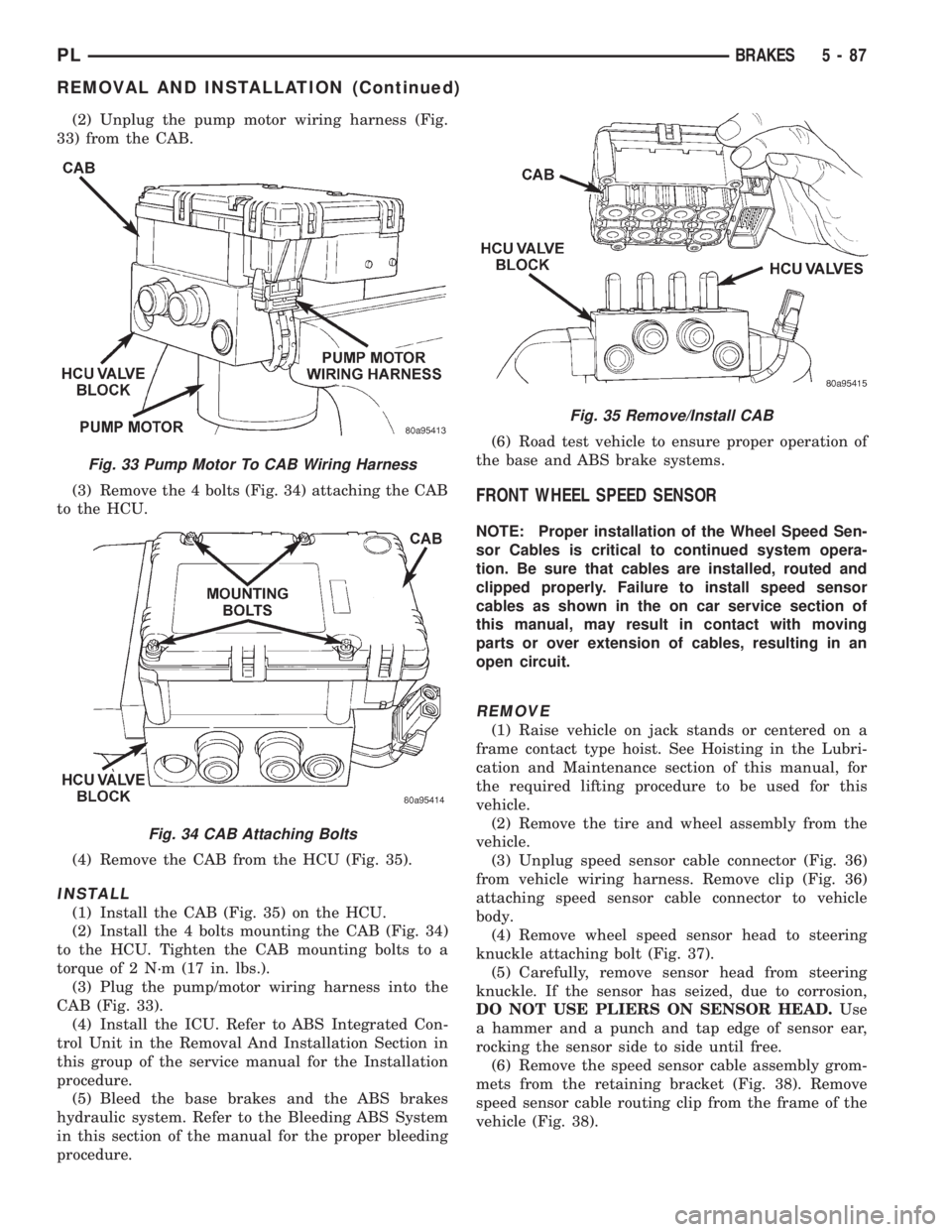
(2) Unplug the pump motor wiring harness (Fig.
33) from the CAB.
(3) Remove the 4 bolts (Fig. 34) attaching the CAB
to the HCU.
(4) Remove the CAB from the HCU (Fig. 35).
INSTALL
(1) Install the CAB (Fig. 35) on the HCU.
(2) Install the 4 bolts mounting the CAB (Fig. 34)
to the HCU. Tighten the CAB mounting bolts to a
torque of 2 N´m (17 in. lbs.).
(3) Plug the pump/motor wiring harness into the
CAB (Fig. 33).
(4) Install the ICU. Refer to ABS Integrated Con-
trol Unit in the Removal And Installation Section in
this group of the service manual for the Installation
procedure.
(5) Bleed the base brakes and the ABS brakes
hydraulic system. Refer to the Bleeding ABS System
in this section of the manual for the proper bleeding
procedure.(6) Road test vehicle to ensure proper operation of
the base and ABS brake systems.
FRONT WHEEL SPEED SENSOR
NOTE: Proper installation of the Wheel Speed Sen-
sor Cables is critical to continued system opera-
tion. Be sure that cables are installed, routed and
clipped properly. Failure to install speed sensor
cables as shown in the on car service section of
this manual, may result in contact with moving
parts or over extension of cables, resulting in an
open circuit.
REMOVE
(1) Raise vehicle on jack stands or centered on a
frame contact type hoist. See Hoisting in the Lubri-
cation and Maintenance section of this manual, for
the required lifting procedure to be used for this
vehicle.
(2) Remove the tire and wheel assembly from the
vehicle.
(3) Unplug speed sensor cable connector (Fig. 36)
from vehicle wiring harness. Remove clip (Fig. 36)
attaching speed sensor cable connector to vehicle
body.
(4) Remove wheel speed sensor head to steering
knuckle attaching bolt (Fig. 37).
(5) Carefully, remove sensor head from steering
knuckle. If the sensor has seized, due to corrosion,
DO NOT USE PLIERS ON SENSOR HEAD.Use
a hammer and a punch and tap edge of sensor ear,
rocking the sensor side to side until free.
(6) Remove the speed sensor cable assembly grom-
mets from the retaining bracket (Fig. 38). Remove
speed sensor cable routing clip from the frame of the
vehicle (Fig. 38).
Fig. 33 Pump Motor To CAB Wiring Harness
Fig. 34 CAB Attaching Bolts
Fig. 35 Remove/Install CAB
PLBRAKES 5 - 87
REMOVAL AND INSTALLATION (Continued)
Page 170 of 1200
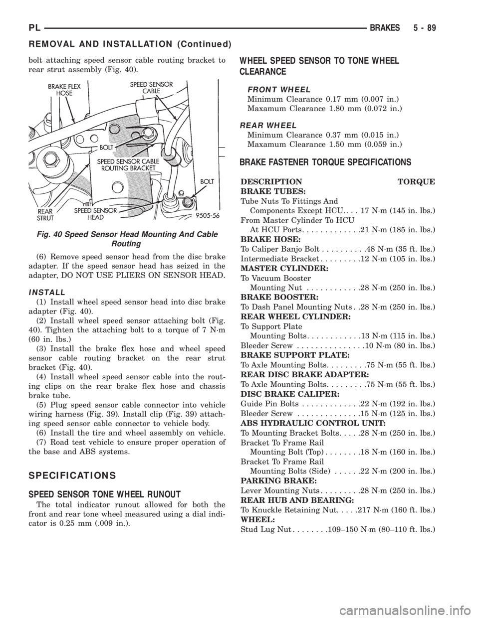
bolt attaching speed sensor cable routing bracket to
rear strut assembly (Fig. 40).
(6) Remove speed sensor head from the disc brake
adapter. If the speed sensor head has seized in the
adapter, DO NOT USE PLIERS ON SENSOR HEAD.
INSTALL
(1) Install wheel speed sensor head into disc brake
adapter (Fig. 40).
(2) Install wheel speed sensor attaching bolt (Fig.
40). Tighten the attaching bolt to a torque of 7 N´m
(60 in. lbs.)
(3) Install the brake flex hose and wheel speed
sensor cable routing bracket on the rear strut
bracket (Fig. 40).
(4) Install wheel speed sensor cable into the rout-
ing clips on the rear brake flex hose and chassis
brake tube.
(5) Plug speed sensor cable connector into vehicle
wiring harness (Fig. 39). Install clip (Fig. 39) attach-
ing speed sensor cable connector to vehicle body.
(6) Install the tire and wheel assembly on vehicle.
(7) Road test vehicle to ensure proper operation of
the base and ABS systems.
SPECIFICATIONS
SPEED SENSOR TONE WHEEL RUNOUT
The total indicator runout allowed for both the
front and rear tone wheel measured using a dial indi-
cator is 0.25 mm (.009 in.).
WHEEL SPEED SENSOR TO TONE WHEEL
CLEARANCE
FRONT WHEEL
Minimum Clearance 0.17 mm (0.007 in.)
Maxamum Clearance 1.80 mm (0.072 in.)
REAR WHEEL
Minimum Clearance 0.37 mm (0.015 in.)
Maxamum Clearance 1.50 mm (0.059 in.)
BRAKE FASTENER TORQUE SPECIFICATIONS
DESCRIPTION TORQUE
BRAKE TUBES:
Tube Nuts To Fittings And
Components Except HCU. . . . 17 N´m (145 in. lbs.)
From Master Cylinder To HCU
At HCU Ports.............21N´m(185 in. lbs.)
BRAKE HOSE:
To Caliper Banjo Bolt..........48N´m(35ft.lbs.)
Intermediate Bracket.........12N´m(105 in. lbs.)
MASTER CYLINDER:
To Vacuum Booster
Mounting Nut............28N´m(250 in. lbs.)
BRAKE BOOSTER:
To Dash Panel Mounting Nuts . .28 N´m (250 in. lbs.)
REAR WHEEL CYLINDER:
To Support Plate
Mounting Bolts............13N´m(115in.lbs.)
Bleeder Screw...............10N´m(80in.lbs.)
BRAKE SUPPORT PLATE:
To Axle Mounting Bolts.........75N´m(55ft.lbs.)
REAR DISC BRAKE ADAPTER:
To Axle Mounting Bolts.........75N´m(55ft.lbs.)
DISC BRAKE CALIPER:
Guide Pin Bolts.............22N´m(192 in. lbs.)
Bleeder Screw..............15N´m(125 in. lbs.)
ABS HYDRAULIC CONTROL UNIT:
To Mounting Bracket Bolts.....28N´m(250 in. lbs.)
Bracket To Frame Rail
Mounting Bolt (Top)........18N´m(160 in. lbs.)
Bracket To Frame Rail
Mounting Bolts (Side)......22N´m(200 in. lbs.)
PARKING BRAKE:
Lever Mounting Nuts.........28N´m(250 in. lbs.)
REAR HUB AND BEARING:
To Knuckle Retaining Nut.....217 N´m (160 ft. lbs.)
WHEEL:
Stud Lug Nut........109±150 N´m (80±110 ft. lbs.)
Fig. 40 Speed Sensor Head Mounting And Cable
Routing
PLBRAKES 5 - 89
REMOVAL AND INSTALLATION (Continued)
Page 173 of 1200
The clutch cable has a unique self-adjuster mecha-
nism built into the cable which compensates for
clutch disc wear. The cable requires no maintenance
or lubrication. There are no serviceable components
on the cable assembly.
The clutch pedal is connected to the cable through
a plastic spacer. The upper end of the clutch pedal
pivots in the pedal bracket on two nylon bushings
and a shaft. These bushings are greased at assembly
and do not require periodic lubrication.
CLUTCH DISC AND COVER APPLICATION
The 2.0 single overhead cam engine uses a 216 mm
(8.5 in.) clutch disc. The manual transaxle is avail-
able only with the 2.0 liter engine.
CLUTCH REPLACEMENT
The transaxle must be removed to service the
clutch disc, pressure plate, flywheel/drive plate,
and/or clutch release bearing and lever.
DESCRIPTION AND OPERATION
CLUTCH CABLE
The manual transaxle clutch release system has a
unique self-adjusting mechanism to compensate for
clutch disc wear. This adjuster mechanism is located
within the clutch cable assembly. The preload spring
maintains tension on the cable. This tension keeps
the clutch release bearing continuously loaded
against the fingers of the clutch cover assembly.
CLUTCH PEDAL POSITION SWITCH
The clutch pedal position switch functions as a
safety interlock device. It prevents possible engine
cranking with the clutch engaged.
The clutch pedal position switch is wired in series
between the starter relay coil and the ignition
switch.
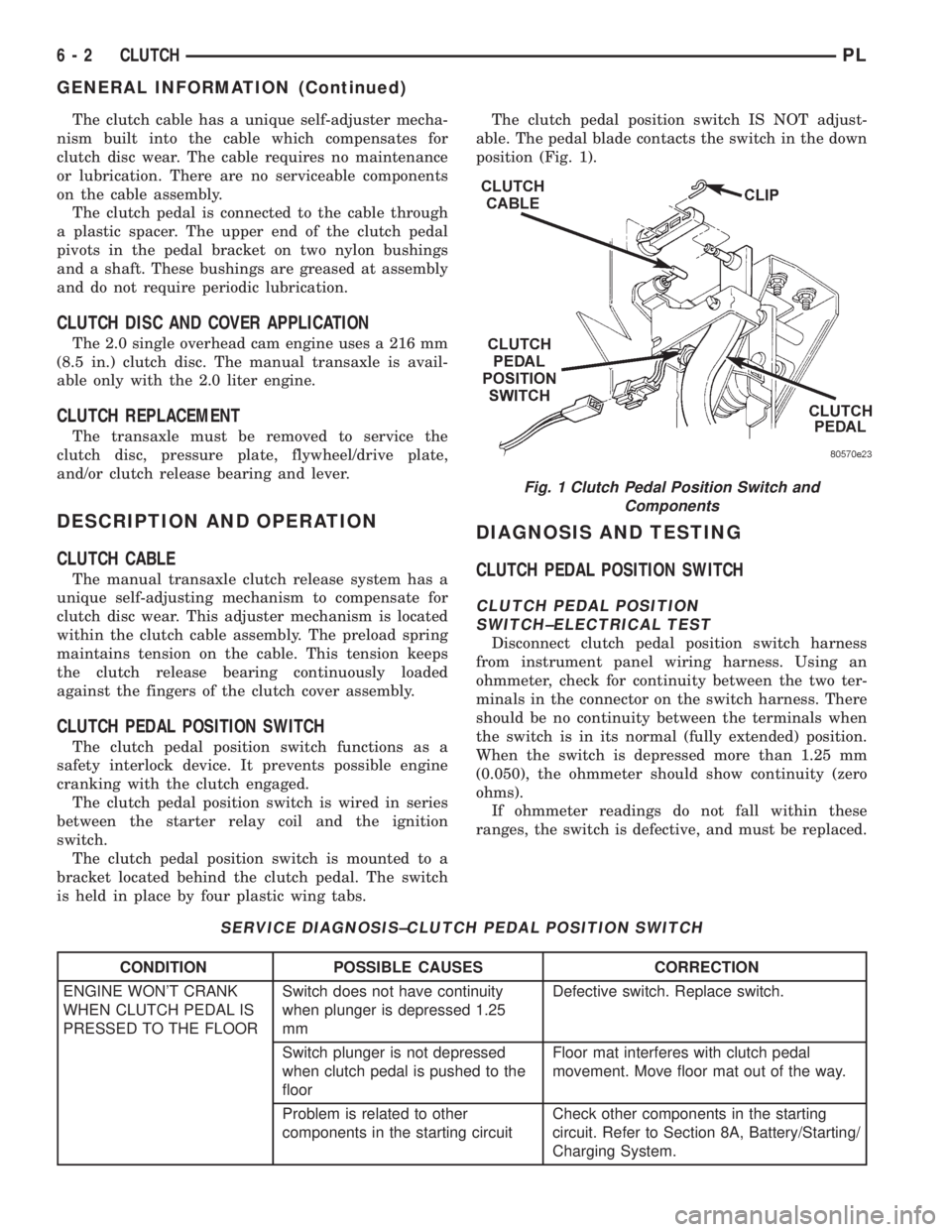
The clutch pedal position switch is mounted to a
bracket located behind the clutch pedal. The switch
is held in place by four plastic wing tabs.The clutch pedal position switch IS NOT adjust-
able. The pedal blade contacts the switch in the down
position (Fig. 1).
DIAGNOSIS AND TESTING
CLUTCH PEDAL POSITION SWITCH
CLUTCH PEDAL POSITION
SWITCH±ELECTRICAL TEST
Disconnect clutch pedal position switch harness
from instrument panel wiring harness. Using an
ohmmeter, check for continuity between the two ter-
minals in the connector on the switch harness. There
should be no continuity between the terminals when
the switch is in its normal (fully extended) position.
When the switch is depressed more than 1.25 mm
(0.050), the ohmmeter should show continuity (zero
ohms).
If ohmmeter readings do not fall within these
ranges, the switch is defective, and must be replaced.
SERVICE DIAGNOSIS±CLUTCH PEDAL POSITION SWITCH
CONDITION POSSIBLE CAUSES CORRECTION
ENGINE WON'T CRANK
WHEN CLUTCH PEDAL IS
PRESSED TO THE FLOORSwitch does not have continuity
when plunger is depressed 1.25
mmDefective switch. Replace switch.
Switch plunger is not depressed
when clutch pedal is pushed to the
floorFloor mat interferes with clutch pedal
movement. Move floor mat out of the way.
Problem is related to other
components in the starting circuitCheck other components in the starting
circuit. Refer to Section 8A, Battery/Starting/
Charging System.
Fig. 1 Clutch Pedal Position Switch and
Components
6 - 2 CLUTCHPL
GENERAL INFORMATION (Continued)
Page 179 of 1200
REMOVAL
(1) Remove transaxle. See Group 21, Manual Tran-
saxle, for procedure.
(2) Mark clutch cover and flywheel, to maintain
their same relative positions when installing clutch
assembly.
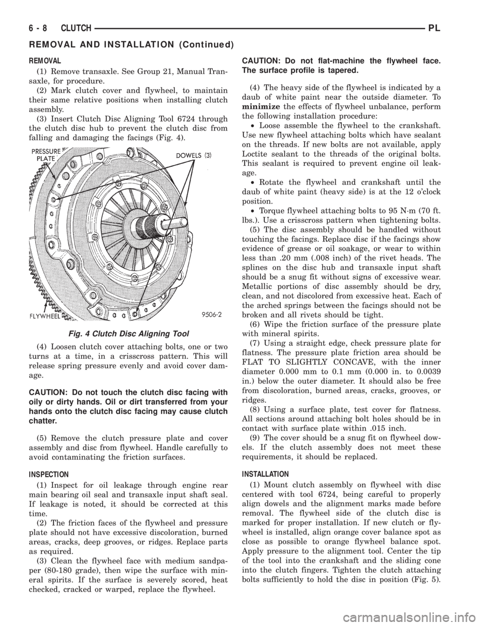
(3) Insert Clutch Disc Aligning Tool 6724 through
the clutch disc hub to prevent the clutch disc from
falling and damaging the facings (Fig. 4).
(4) Loosen clutch cover attaching bolts, one or two
turns at a time, in a crisscross pattern. This will
release spring pressure evenly and avoid cover dam-
age.
CAUTION: Do not touch the clutch disc facing with
oily or dirty hands. Oil or dirt transferred from your
hands onto the clutch disc facing may cause clutch
chatter.
(5) Remove the clutch pressure plate and cover
assembly and disc from flywheel. Handle carefully to
avoid contaminating the friction surfaces.
INSPECTION
(1) Inspect for oil leakage through engine rear
main bearing oil seal and transaxle input shaft seal.
If leakage is noted, it should be corrected at this
time.
(2) The friction faces of the flywheel and pressure
plate should not have excessive discoloration, burned
areas, cracks, deep grooves, or ridges. Replace parts
as required.
(3) Clean the flywheel face with medium sandpa-
per (80-180 grade), then wipe the surface with min-
eral spirits. If the surface is severely scored, heat
checked, cracked or warped, replace the flywheel.CAUTION: Do not flat-machine the flywheel face.
The surface profile is tapered.
(4) The heavy side of the flywheel is indicated by a
daub of white paint near the outside diameter. To
minimizethe effects of flywheel unbalance, perform
the following installation procedure:
²Loose assemble the flywheel to the crankshaft.
Use new flywheel attaching bolts which have sealant
on the threads. If new bolts are not available, apply
Loctite sealant to the threads of the original bolts.
This sealant is required to prevent engine oil leak-
age.
²Rotate the flywheel and crankshaft until the
daub of white paint (heavy side) is at the 12 o'clock
position.
²Torque flywheel attaching bolts to 95 N´m (70 ft.
lbs.). Use a crisscross pattern when tightening bolts.
(5) The disc assembly should be handled without
touching the facings. Replace disc if the facings show
evidence of grease or oil soakage, or wear to within
less than .20 mm (.008 inch) of the rivet heads. The
splines on the disc hub and transaxle input shaft
should be a snug fit without signs of excessive wear.
Metallic portions of disc assembly should be dry,
clean, and not discolored from excessive heat. Each of
the arched springs between the facings should not be
broken and all rivets should be tight.
(6) Wipe the friction surface of the pressure plate
with mineral spirits.
(7) Using a straight edge, check pressure plate for
flatness. The pressure plate friction area should be
FLAT TO SLIGHTLY CONCAVE, with the inner
diameter 0.000 mm to 0.1 mm (0.000 in. to 0.0039
in.) below the outer diameter. It should also be free
from discoloration, burned areas, cracks, grooves, or
ridges.
(8) Using a surface plate, test cover for flatness.
All sections around attaching bolt holes should be in
contact with surface plate within .015 inch.
(9) The cover should be a snug fit on flywheel dow-
els. If the clutch assembly does not meet these
requirements, it should be replaced.
INSTALLATION
(1) Mount clutch assembly on flywheel with disc
centered with tool 6724, being careful to properly
align dowels and the alignment marks made before
removal. The flywheel side of the clutch disc is
marked for proper installation. If new clutch or fly-
wheel is installed, align orange cover balance spot as
close as possible to orange flywheel balance spot.
Apply pressure to the alignment tool. Center the tip
of the tool into the crankshaft and the sliding cone
into the clutch fingers. Tighten the clutch attaching
bolts sufficiently to hold the disc in position (Fig. 5).
Fig. 4 Clutch Disc Aligning Tool
6 - 8 CLUTCHPL
REMOVAL AND INSTALLATION (Continued)
Page 184 of 1200
CLUTCH
CONTENTS
page page
GENERAL INFORMATION
CLUTCH COMPONENTS Ð RIGHT HAND
DRIVE (RHD)........................ 1
CLUTCH DISC AND COVER APPLICATION Ð
RIGHT HAND DRIVE (RHD)............. 1
CLUTCH REPLACEMENT Ð RIGHT HAND
DRIVE (RHD)........................ 1
DESCRIPTION AND OPERATION
CLUTCH PEDAL POSITION SWITCH Ð RIGHT
HAND DRIVE (RHD)................... 2
HYDRAULIC CLUTCH SYSTEM Ð RIGHT
HAND DRIVE (RHD)................... 2
DIAGNOSIS AND TESTING
CLASH±INTO±REVERSE COMPLAINTS...... 6CLUTCH DIAGNOSIS Ð RIGHT HAND DRIVE
(RHD).............................. 2
REMOVAL AND INSTALLATION
CLUTCH ASSEMBLY Ð RIGHT HAND DRIVE
(RHD).............................. 8
CLUTCH MASTER CYLINDER Ð RIGHT HAND
DRIVE (RHD)........................ 6
CLUTCH PEDAL POSITION SWITCH Ð RIGHT
HAND DRIVE (RHD)................... 8
HYDRAULIC SLAVE CYLINDER Ð RIGHT
HAND DRIVE (RHD)................... 7
SPECIFICATIONS
NV T350 (A-578) CLUTCH TIGHTENING
REFERENCE.......................... 9
GENERAL INFORMATION
CLUTCH COMPONENTS Ð RIGHT HAND DRIVE
(RHD)
The modular clutch assembly used in this vehicle
consists of a single, dry-type clutch disc and a dia-
phragm style clutch cover.
The clutch disc has cushion springs riveted to the
disc hub assembly. The clutch disc facings are riveted
to the cushion springs. The facings are made from a
non-asbestos material.
The clutch cover pressure plate assembly is a dia-
phragm type unit with a one-piece diaphragm spring
with multiple release fingers. The pressure plate
release fingers are preset during manufacture and
are not adjustable.
A sleeve-type release bearing is used to engage and
disengage the clutch cover pressure plate. The bear-
ing is prelubed during manufacture and is a sealed
unit.
The release bearing is operated by a pivoting
release fork in the clutch housing. The fork pivots on
a ball stud within the housing. The release fork is
actuated by a hydraulic clutch system.
The hydraulic clutch automatically adjusts for any
slack in the mechanism. This compensates for clutch
disc wear. The system requires no maintenance or
lubrication.
The clutch pedal is connected to the clutch master
cylinder through a plastic bushing. The upper end of
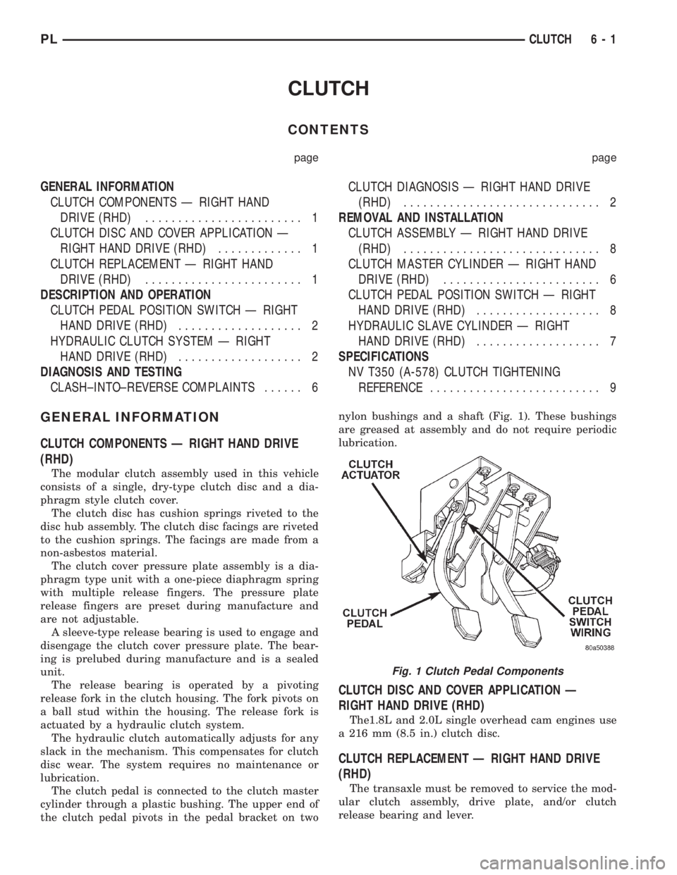
the clutch pedal pivots in the pedal bracket on twonylon bushings and a shaft (Fig. 1). These bushings
are greased at assembly and do not require periodic
lubrication.
CLUTCH DISC AND COVER APPLICATION Ð
RIGHT HAND DRIVE (RHD)
The1.8L and 2.0L single overhead cam engines use
a 216 mm (8.5 in.) clutch disc.
CLUTCH REPLACEMENT Ð RIGHT HAND DRIVE
(RHD)
The transaxle must be removed to service the mod-
ular clutch assembly, drive plate, and/or clutch
release bearing and lever.
Fig. 1 Clutch Pedal Components
PLCLUTCH 6 - 1
Page 196 of 1200
ENGINE THERMOSTAT
The engine thermostat is located on the front of
the engine (radiator side) in the thermostat housing/
engine outlet connector. The thermostat has an air
bleed (vent) located in the flange and a O-ring for
sealing incorporate on it. There is a relief in the ther-
mostat housing/outlet connector for the O-ring.
WATER PUMP
The water pump has a diecast aluminum body and
housing with a stamped steel impeller. The water
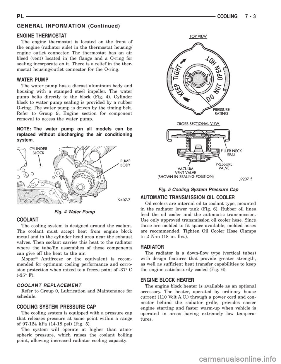
pump bolts directly to the block (Fig. 4). Cylinder
block to water pump sealing is provided by a rubber
O-ring. The water pump is driven by the timing belt.
Refer to Group 9, Engine section for component
removal to access the water pump.
NOTE: The water pump on all models can be
replaced without discharging the air conditioning
system.
COOLANT
The cooling system is designed around the coolant.
The coolant must accept heat from engine block
metal and in the cylinder head area near the exhaust
valves. Then coolant carries this heat to the radiator
where the tube/fin assemblies of these components
can give off the heat to the air.
MopartAntifreeze or the equivalent is recom-
mended for optimum cooling performance and corro-
sion protection when mixed to a freeze point of -37É C
(-35É F).
COOLANT REPLACEMENT
Refer to Group 0, Lubrication and Maintenance for
schedule.
COOLING SYSTEM PRESSURE CAP
The cooling system is equipped with a pressure cap
that releases pressure at some point within a range
of 97-124 kPa (14-18 psi) (Fig. 5).
The system will operate at higher than atmo-
spheric pressure, which raises the coolant boiling
point, allowing increased radiator cooling capacity.
AUTOMATIC TRANSMISSION OIL COOLER
Oil coolers are internal oil to coolant type, mounted
in the radiator lower tank (Fig. 6). Rubber oil lines
feed the oil cooler and the automatic transmission.
Use only approved transmission oil cooler hose. Since
these are molded to fit space available, molded hoses
are recommended. Tighten Oil Cooler Hose Clamps
to 2 N´m (18 in. lbs.).
RADIATOR
The radiator is a down-flow type (vertical tubes)
with design features that provide greater strength,
as well as sufficient heat transfer capabilities to keep
the engine satisfactorily cooled (Fig. 6).
ENGINE BLOCK HEATER
The engine block heater is available as an optional
accessory. The heater, operated by ordinary house
current (110 Volt A.C.) through a power cord and con-
nector behind the radiator grille, provides easier
engine starting and faster warm-up when vehicle is
operated in areas having extremely low tempera-
tures.
Fig. 4 Water Pump
Fig. 5 Cooling System Pressure Cap
PLCOOLING 7 - 3
GENERAL INFORMATION (Continued)
Page 198 of 1200
SELECTION AND ADDITIVES
The use of aluminum cylinder heads, intake mani-
folds DOHC, and water pumps requires special corro-
sion protection. MopartAntifreeze or the equivalent
is recommended for best engine cooling without cor-
rosion. When mixed only to a freeze point of -37ÉC
(-35ÉF) to -59ÉC (-50ÉF). If it looses color or becomes
contaminated, drain, flush, and replace with fresh
properly mixed solution.
COOLING SYSTEM PRESSURE CAP
The cooling system is equipped with a pressure cap
that releases built up pressure, maintaining a range
of 97-124 kPa (14-18 psi).
The cooling system will operate at higher than
atmospheric pressure. The higher pressure raises the
coolant boiling point thus, allowing increased radia-
tor cooling capacity.
There is a vent valve in the center of the cap that
allows a small coolant flow from the coolant reserve
system (CRS) tank. This valve is spring loaded in the
closed position. However it must be free to open dur-
ing system cool-down.If the valve is stuck shut,
the radiator hoses will collapse on cool-down.
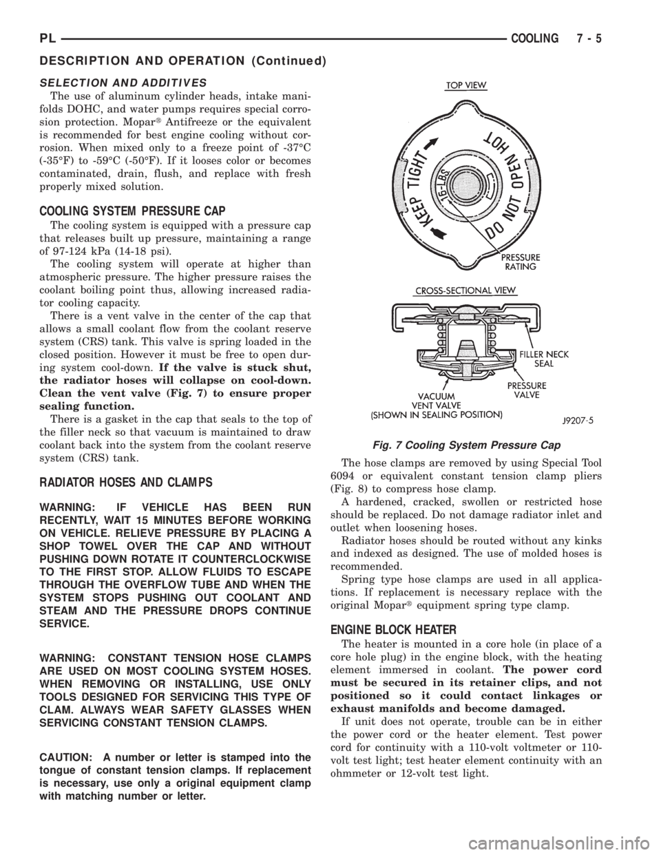
Clean the vent valve (Fig. 7) to ensure proper
sealing function.
There is a gasket in the cap that seals to the top of
the filler neck so that vacuum is maintained to draw
coolant back into the system from the coolant reserve
system (CRS) tank.
RADIATOR HOSES AND CLAMPS
WARNING: IF VEHICLE HAS BEEN RUN
RECENTLY, WAIT 15 MINUTES BEFORE WORKING
ON VEHICLE. RELIEVE PRESSURE BY PLACING A
SHOP TOWEL OVER THE CAP AND WITHOUT
PUSHING DOWN ROTATE IT COUNTERCLOCKWISE
TO THE FIRST STOP. ALLOW FLUIDS TO ESCAPE
THROUGH THE OVERFLOW TUBE AND WHEN THE
SYSTEM STOPS PUSHING OUT COOLANT AND
STEAM AND THE PRESSURE DROPS CONTINUE
SERVICE.
WARNING: CONSTANT TENSION HOSE CLAMPS
ARE USED ON MOST COOLING SYSTEM HOSES.
WHEN REMOVING OR INSTALLING, USE ONLY
TOOLS DESIGNED FOR SERVICING THIS TYPE OF
CLAM. ALWAYS WEAR SAFETY GLASSES WHEN
SERVICING CONSTANT TENSION CLAMPS.
CAUTION: A number or letter is stamped into the
tongue of constant tension clamps. If replacement
is necessary, use only a original equipment clamp
with matching number or letter.The hose clamps are removed by using Special Tool
6094 or equivalent constant tension clamp pliers
(Fig. 8) to compress hose clamp.
A hardened, cracked, swollen or restricted hose
should be replaced. Do not damage radiator inlet and
outlet when loosening hoses.
Radiator hoses should be routed without any kinks
and indexed as designed. The use of molded hoses is
recommended.
Spring type hose clamps are used in all applica-
tions. If replacement is necessary replace with the
original Mopartequipment spring type clamp.
ENGINE BLOCK HEATER
The heater is mounted in a core hole (in place of a
core hole plug) in the engine block, with the heating
element immersed in coolant.The power cord
must be secured in its retainer clips, and not
positioned so it could contact linkages or
exhaust manifolds and become damaged.
If unit does not operate, trouble can be in either
the power cord or the heater element. Test power
cord for continuity with a 110-volt voltmeter or 110-
volt test light; test heater element continuity with an
ohmmeter or 12-volt test light.
Fig. 7 Cooling System Pressure Cap
PLCOOLING 7 - 5
DESCRIPTION AND OPERATION (Continued)