1999 DODGE NEON service indicator
[x] Cancel search: service indicatorPage 1068 of 1200
TIRES AND WHEELS
CONTENTS
page page
TIRES.................................. 1WHEELS................................ 8
TIRES
INDEX
page page
DESCRIPTION AND OPERATION
RADIAL-PLY TIRES....................... 2
REPLACEMENT TIRES.................... 3
SPARE TIRE±TEMPORARY................. 2
TIRE INFLATION PRESSURES.............. 2
TIRE INFORMATION...................... 1
TIRE PRESSURE FOR HIGH SPEED
OPERATION........................... 3
DIAGNOSIS AND TESTING
LEAD CORRECTION CHART................ 4
PRESSURE GAUGES..................... 3TIRE NOISE OR VIBRATION................ 4
TIRE WEAR PATTERNS.................... 3
TREAD WEAR INDICATORS................ 3
SERVICE PROCEDURES
REPAIRING TIRE LEAKS................... 4
TIRE AND WHEEL MATCH MOUNTING........ 6
TIRE AND WHEEL ROTATION............... 4
CLEANING AND INSPECTION
CLEANING TIRES........................ 7
SPECIFICATIONS
TIRE SPECIFICATIONS.................... 7
DESCRIPTION AND OPERATION
TIRE INFORMATION
Tires are designed and engineered for each specific
vehicle. They provide the best overall performance
for normal operation. The ride and handling charac-
teristics match the vehicle's requirements. With
proper care they will give excellent reliability, trac-
tion, skid resistance, and tread life.
Driving habits have more effect on tire life than
any other factor. Careful drivers will obtain, in most
cases, much greater mileage than severe use or care-
less drivers. A few of the driving habits which will
shorten the life of any tire are:
²Rapid acceleration
²Severe application of brakes
²High-speed driving
²Taking turns at excessive speeds
²Striking curbs and other obstacles
²Operating vehicle with over or under inflated
tire pressures
Radial ply tires are more prone to irregular tread
wear. It is important to follow the tire rotation inter-
val shown in the section on Tire Rotation. This will
help to achieve a greater tread-life potential.
TIRE IDENTIFICATION
Tire type, size, aspect ratio and speed rating are
encoded in the letters and numbers imprinted on the
side wall of the tire. Refer to the chart to decipher
the tire identification code (Fig. 1).
Performance tires will have a speed rating letter
after the aspect ratio number. The speed rating is not
always printed on the tire sidewall. The letterSindi-
cates that the tire is speed rated up to 112 mph.
²Qup to 100 mph
²Tup to 118 mph
²Uup to 124 mph
²Hup to 130 mph
²Vup to 149 mph
²Zmore than 149 mph (consult the tire manu-
facturer for the specific speed rating)
An All Season type tire will have eitherM+S,M
&SorM-S(indicating mud and snow traction)
imprinted on the side wall.
TIRE CHAINS
Refer to the owners manual supplied with this
vehicle to determine whether the use of tire chains is
permitted on this vehicle.
PLTIRES AND WHEELS 22 - 1
Page 1073 of 1200

Install wheel on vehicle, and progressively tighten
the 5 wheel nuts to a torque of 135 N´m (100 ft. lbs.).
TIRE AND WHEEL MATCH MOUNTING
Wheels and tires are match mounted at the factory.
This means that the high spot of the tire is matched
to the low spot on the wheel rim. This technique is
used to reduce run-out in the wheel/tire assembly.
The high spot on the tire is marked with a paint
mark or a bright colored adhesive label on the out-
board sidewall. The low spot on the rim is identified
with a label on the outside of the rim and a dot or
line on the inside of the rim. If the outside label has
been removed the tire will have to be removed to
locate the dot or line on the inside of the rim.Before dismounting a tire from its wheel, a refer-
ence mark should be placed on the tire at the valve
stem location. This reference will ensure that it is
remounted in the original position on the wheel.
(1) Measure the total indicator runout on the cen-
ter of the tire tread rib. Record the indicator reading.
Mark the tire to indicate the high spot. Place a mark
on the tire at the valve stem location (Fig. 8).
(2) Break down the tire and remount it 180
degrees on the rim (Fig. 9).
Fig. 6 Forward-Cross Tire Rotation Method
Fig. 7 Tire Repair Area
Fig. 8 First Measurement On Tire
Fig. 9 Remount Tire 180 Degrees
22 - 6 TIRES AND WHEELSPL
SERVICE PROCEDURES (Continued)
Page 1074 of 1200

(3) Measure the total indicator runout again. Mark
the tire to indicate the high spot.
(4) If runout is still excessive, the following proce-
dures must be done.
²If the high spot is within 102 mm (4.0 in.) of the
first spot and is still excessive, replace the tire.
²If the high spot is within 102 mm (4.0 in.) of the
first spot on the wheel, the wheel may be out of spec-
ifications. Refer to Wheel and Tire Runout.
²If the high spot is NOT within 102 mm (4.0 in.)
of either high spot, draw an arrow on the tread from
second high spot to first. Break down the tire and
remount it 90 degrees on rim in that direction (Fig.
10). This procedure will normally reduce the runout
to an acceptable amount.
CLEANING AND INSPECTION
CLEANING TIRES
Remove protective coating on tires before delivery
of vehicle. This coating may cause deterioration of
tires.
To remove the protective coating applying warm
water and let it soak for a few minutes. Then scrub
the coating away with a soft bristle brush. Steam
cleaning may also be used to remove the coating.
NOTE: DO NOT use gasoline, mineral oil, oil-based
solvent or wire brush for cleaning.
SPECIFICATIONS
TIRE SPECIFICATIONS
Fig. 10 Remount Tire 90 Degrees In Direction of
Arrow
PLTIRES AND WHEELS 22 - 7
SERVICE PROCEDURES (Continued)
Page 1154 of 1200
(4) Install pulley assembly retaining snap ring
(bevel side outward) with Snap Ring Pliers. Press the
snap ring to make sure it is properly seated in the
groove.
(5) If the original front plate assembly and pulley
assembly are to be reused, the old shim(s) can be
used. If not, place a trial stack of shims, 2.54 mm
(0.10 in.) thick, on the shaft against the shoulder.
(6) Install front plate assembly onto shaft.
(7) If installing a new front plate and/or pulley
assembly, the gap between front plate and pulley face
must be checked. Use the following procedure:
(a) Attach a dial indicator to front plate so that
movement of the plate can be measured.
(b) With the dial indicator zeroed on the front
plate, energize the clutch and record the amount of
movement.
(c) The readings should be 0.35 to 0.65 mm
(0.014 to 0.026 in.). If proper reading is not
obtained, add or subtract shims until desired read-
ing is obtained.
(8) Install compressor shaft bolt. Tighten to 17.5
62 N´m (155620 in. lbs.) torque.
NOTE: Shims may compress after tightening shaft
nut. Check air gap in four or more places to verify if
air gap is still correct. Spin pulley for final check.
CLUTCH BREAK-IN
After new clutch installation, cycle the A/C clutch
20 times (5 seconds on and 5 seconds off). During
this procedure, set the system to the A/C mode,
engine rpm at 1500 - 2000, and high blower speed.
This procedure (burnishing) will seat the opposing
friction surfaces and provide a higher clutch torque
capability.
CONDENSATION DRAIN TUBE
REMOVAL
(1) Raise vehicle.
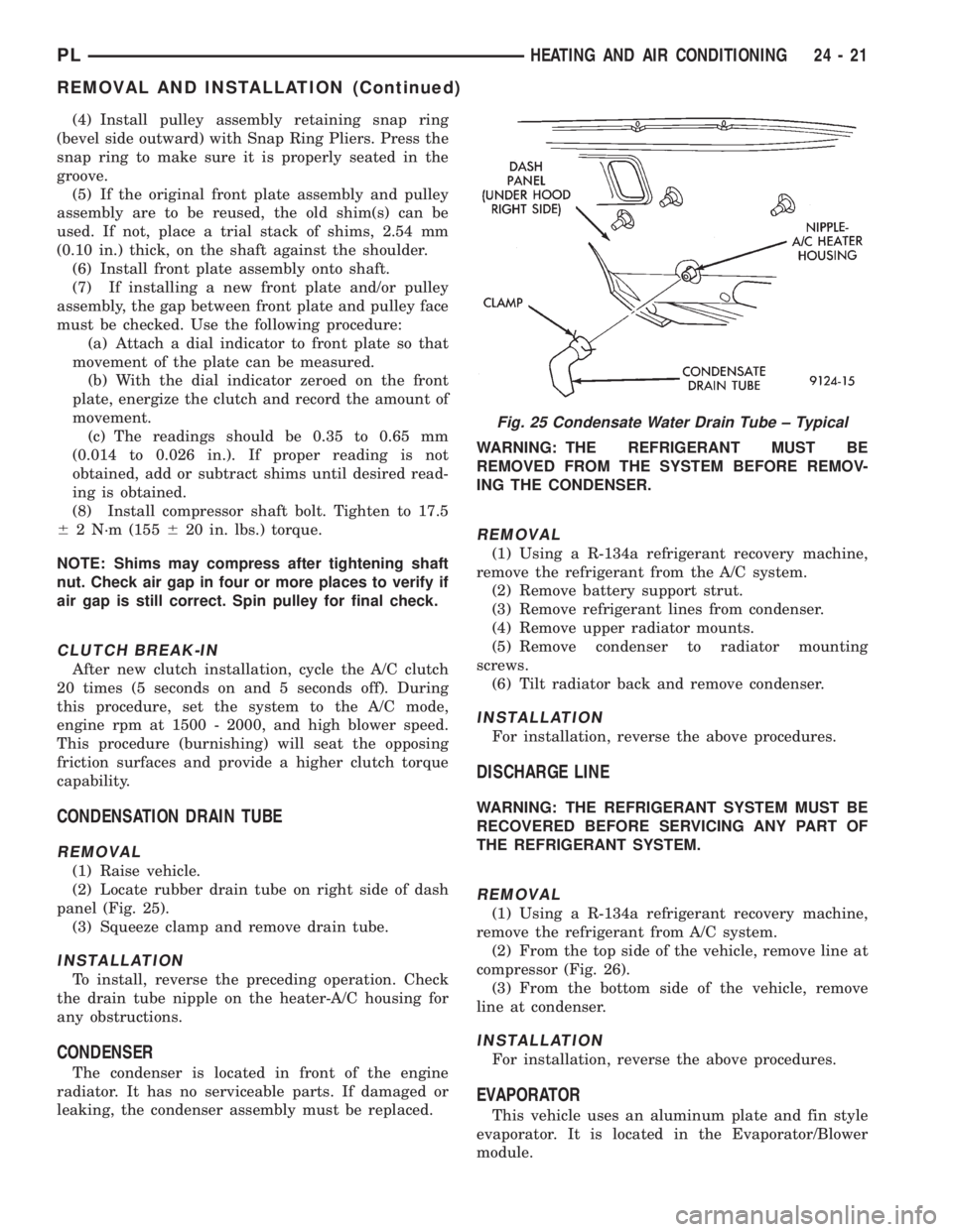
(2) Locate rubber drain tube on right side of dash
panel (Fig. 25).
(3) Squeeze clamp and remove drain tube.
INSTALLATION
To install, reverse the preceding operation. Check
the drain tube nipple on the heater-A/C housing for
any obstructions.
CONDENSER
The condenser is located in front of the engine
radiator. It has no serviceable parts. If damaged or
leaking, the condenser assembly must be replaced.WARNING: THE REFRIGERANT MUST BE
REMOVED FROM THE SYSTEM BEFORE REMOV-
ING THE CONDENSER.
REMOVAL
(1) Using a R-134a refrigerant recovery machine,
remove the refrigerant from the A/C system.
(2) Remove battery support strut.
(3) Remove refrigerant lines from condenser.
(4) Remove upper radiator mounts.
(5) Remove condenser to radiator mounting
screws.
(6) Tilt radiator back and remove condenser.
INSTALLATION
For installation, reverse the above procedures.
DISCHARGE LINE
WARNING: THE REFRIGERANT SYSTEM MUST BE
RECOVERED BEFORE SERVICING ANY PART OF
THE REFRIGERANT SYSTEM.
REMOVAL
(1) Using a R-134a refrigerant recovery machine,
remove the refrigerant from A/C system.
(2) From the top side of the vehicle, remove line at
compressor (Fig. 26).
(3) From the bottom side of the vehicle, remove
line at condenser.
INSTALLATION
For installation, reverse the above procedures.
EVAPORATOR
This vehicle uses an aluminum plate and fin style
evaporator. It is located in the Evaporator/Blower
module.
Fig. 25 Condensate Water Drain Tube ± Typical
PLHEATING AND AIR CONDITIONING 24 - 21
REMOVAL AND INSTALLATION (Continued)
Page 1182 of 1200
DIAGNOSIS AND TESTING
EGR SYSTEM ON-BOARD DIAGNOSTICS
The PCM performs an on-board diagnostic check of
the EGR system. The diagnostic system uses the
electronic EGR transducer for the system tests.
The diagnostic check activates only during selected
engine/driving conditions. When the conditions are
met, the PCM energizes the transducer solenoid to
disable the EGR. The PCM checks for a change in
the heated oxygen sensor signal. If the air-fuel mix-
ture goes lean, the PCM will attempt to enrichen the
mixture. The PCM registers a Diagnostic Trouble
Code (DTC) if the EGR system is not operating cor-
rectly. After registering a DTC, the PCM turns on the
malfunction indicator (Check Engine) lamp after 2
consecutive trips. There are 2 types of failures sensed
by the PCM. The first is a short or open in the elec-
trical solenoid circuit. the second is a mechhanical
failure or loss of vacuum. The Malfunction Indicator
Lamp (MIL) indicates the need for service.
If a problem is indicated by the MIL and a DTC for
the EGR system is set, check for proper operation of
the EGR system. Use the System Test, EGR Gas
Flow Test. If the EGR system tests properly, check
the system using the DRB scan tool. Refer to
On-Board Diagnosis sections in this Group. Also,
refer to the DRB scan tool and the appropriate Pow-
ertrain Diagnostics Procedure manual.
EGR SYSTEM TEST
WARNING: APPLY PARKING BRAKE AND/OR
BLOCK WHEELS BEFORE TESTING THE EGR SYS-
TEM.
(1) Check the condition of all EGR system hoses
and tubes for leaks, blockages, cracks, kinks and
hardening of rubber hoses. Repair and correct these
conditions before performing any tests.
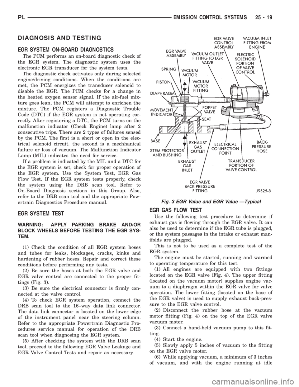
(2) Be sure the hoses at both the EGR valve and
EGR valve control are connected to the proper fit-
tings (Fig. 3).
(3) Be sure the electrical connector is firmly con-
nected at the valve control.
(4) To check EGR system operation, connect the
DRB scan tool to the 16±way data link connector.
The data link connector is located on the lower edge
of the instrument panel near the steering column.
Refer to the appropriate Powertrain Diagnostic Pro-
cedures service manual for operation of the DRB
scan tool when diagnosing the EGR system.
(5) After checking the system with the DRB scan
tool, proceed to the following EGR Valve Leakage and
EGR Valve Control Tests and repair as necessary.
EGR GAS FLOW TEST
Use the following test procedure to determine if
exhaust gas is flowing through the EGR valve. It can
also be used to determine if the EGR tube is plugged,
or the system passages in the intake or exhaust man-
ifolds are plugged.
This is not to be used as a complete test of the
EGR system.
The engine must be started, running and warmed
to operating temperature for this test.
(1) All engines are equipped with two fittings
located on the EGR valve (Fig. 4). The upper fitting
(located on the vacuum motor) supplies engine vac-
uum to a diaphragm within the EGR valve for valve
operation. The lower fitting (located on the base of
the EGR valve) is used to supply exhaust back-pres-
sure to the EGR valve control.
(2) Disconnect the rubber hose at the vacuum
motor fitting (Fig. 4) on the top of the EGR valve
vacuum motor.
(3) Connect a hand-held vacuum pump to this fit-
ting.
(4) Start the engine.
(5) Slowly apply 5 inches of vacuum to the fitting
on the EGR valve motor.
(6) While applying vacuum, a minimum of 3 inches
of vacuum, and with the engine running at idle
Fig. 3 EGR Value and EGR Value ÐTypical
PLEMISSION CONTROL SYSTEMS 25 - 19