1999 DODGE NEON service indicator
[x] Cancel search: service indicatorPage 729 of 1200
FITTING PISTON RINGS
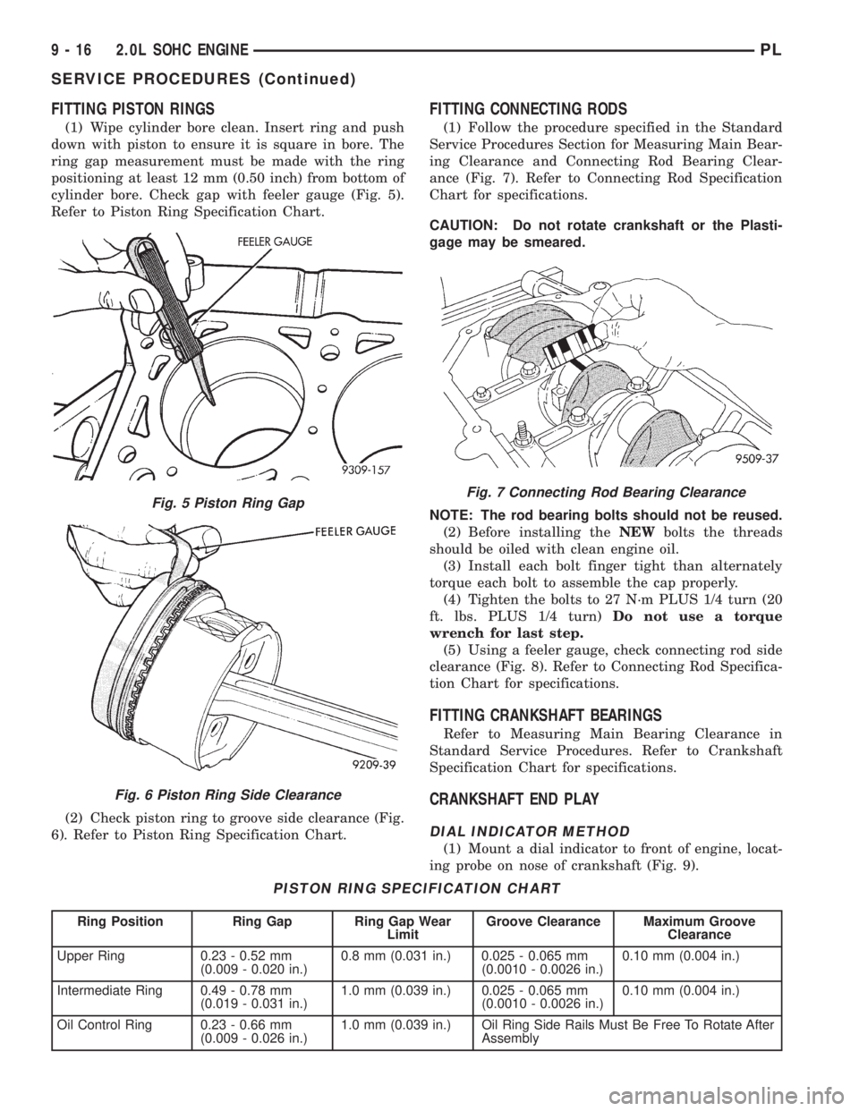
(1) Wipe cylinder bore clean. Insert ring and push
down with piston to ensure it is square in bore. The
ring gap measurement must be made with the ring
positioning at least 12 mm (0.50 inch) from bottom of
cylinder bore. Check gap with feeler gauge (Fig. 5).
Refer to Piston Ring Specification Chart.
(2) Check piston ring to groove side clearance (Fig.
6). Refer to Piston Ring Specification Chart.
FITTING CONNECTING RODS
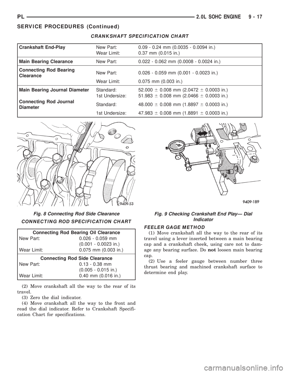
(1) Follow the procedure specified in the Standard
Service Procedures Section for Measuring Main Bear-
ing Clearance and Connecting Rod Bearing Clear-
ance (Fig. 7). Refer to Connecting Rod Specification
Chart for specifications.
CAUTION: Do not rotate crankshaft or the Plasti-
gage may be smeared.
NOTE: The rod bearing bolts should not be reused.
(2) Before installing theNEWbolts the threads
should be oiled with clean engine oil.
(3) Install each bolt finger tight than alternately
torque each bolt to assemble the cap properly.
(4) Tighten the bolts to 27 N´m PLUS 1/4 turn (20
ft. lbs. PLUS 1/4 turn)Do not use a torque
wrench for last step.
(5) Using a feeler gauge, check connecting rod side
clearance (Fig. 8). Refer to Connecting Rod Specifica-
tion Chart for specifications.
FITTING CRANKSHAFT BEARINGS
Refer to Measuring Main Bearing Clearance in
Standard Service Procedures. Refer to Crankshaft
Specification Chart for specifications.
CRANKSHAFT END PLAY
DIAL INDICATOR METHOD
(1) Mount a dial indicator to front of engine, locat-
ing probe on nose of crankshaft (Fig. 9).
Fig. 5 Piston Ring Gap
Fig. 6 Piston Ring Side Clearance
PISTON RING SPECIFICATION CHART
Ring Position Ring Gap Ring Gap Wear
LimitGroove Clearance Maximum Groove
Clearance
Upper Ring 0.23 - 0.52 mm
(0.009 - 0.020 in.)0.8 mm (0.031 in.) 0.025 - 0.065 mm
(0.0010 - 0.0026 in.)0.10 mm (0.004 in.)
Intermediate Ring 0.49 - 0.78 mm
(0.019 - 0.031 in.)1.0 mm (0.039 in.) 0.025 - 0.065 mm
(0.0010 - 0.0026 in.)0.10 mm (0.004 in.)
Oil Control Ring 0.23 - 0.66 mm
(0.009 - 0.026 in.)1.0 mm (0.039 in.) Oil Ring Side Rails Must Be Free To Rotate After
Assembly
Fig. 7 Connecting Rod Bearing Clearance
9 - 16 2.0L SOHC ENGINEPL
SERVICE PROCEDURES (Continued)
Page 730 of 1200
(2) Move crankshaft all the way to the rear of its
travel.
(3) Zero the dial indicator.
(4) Move crankshaft all the way to the front and
read the dial indicator. Refer to Crankshaft Specifi-
cation Chart for specifications.
FEELER GAGE METHOD
(1) Move crankshaft all the way to the rear of its
travel using a lever inserted between a main bearing
cap and a crankshaft cheek, using care not to dam-
age any bearing surface. Donotloosen main bearing
cap.
(2) Use a feeler gauge between number three
thrust bearing and machined crankshaft surface to
determine end play.
CRANKSHAFT SPECIFICATION CHART
Crankshaft End-PlayNew Part: 0.09 - 0.24 mm (0.0035 - 0.0094 in.)
Wear Limit: 0.37 mm (0.015 in.)
Main Bearing ClearanceNew Part: 0.022 - 0.062 mm (0.0008 - 0.0024 in.)
Connecting Rod Bearing
ClearanceNew Part: 0.026 - 0.059 mm (0.001 - 0.0023 in.)
Wear Limit: 0.075 mm (0.003 in.)
Main Bearing Journal DiameterStandard: 52.00060.008 mm (2.047260.0003 in.)
1st Undersize: 51.98360.008 mm (2.046660.0003 in.)
Connecting Rod Journal
DiameterStandard: 48.00060.008 mm (1.889760.0003 in.)
1st Undersize: 47.98360.008 mm (1.889160.0003 in.)
Fig. 8 Connecting Rod Side Clearance
CONNECTING ROD SPECIFICATION CHART
Connecting Rod Bearing Oil Clearance
New Part: 0.026 - 0.059 mm
(0.001 - 0.0023 in.)
Wear Limit: 0.075 mm (0.003 in.)
Connecting Rod Side Clearance
New Part: 0.13 - 0.38 mm
(0.005 - 0.015 in.)
Wear Limit: 0.40 mm (0.016 in.)
Fig. 9 Checking Crankshaft End PlayÐ Dial
Indicator
PL2.0L SOHC ENGINE 9 - 17
SERVICE PROCEDURES (Continued)
Page 761 of 1200
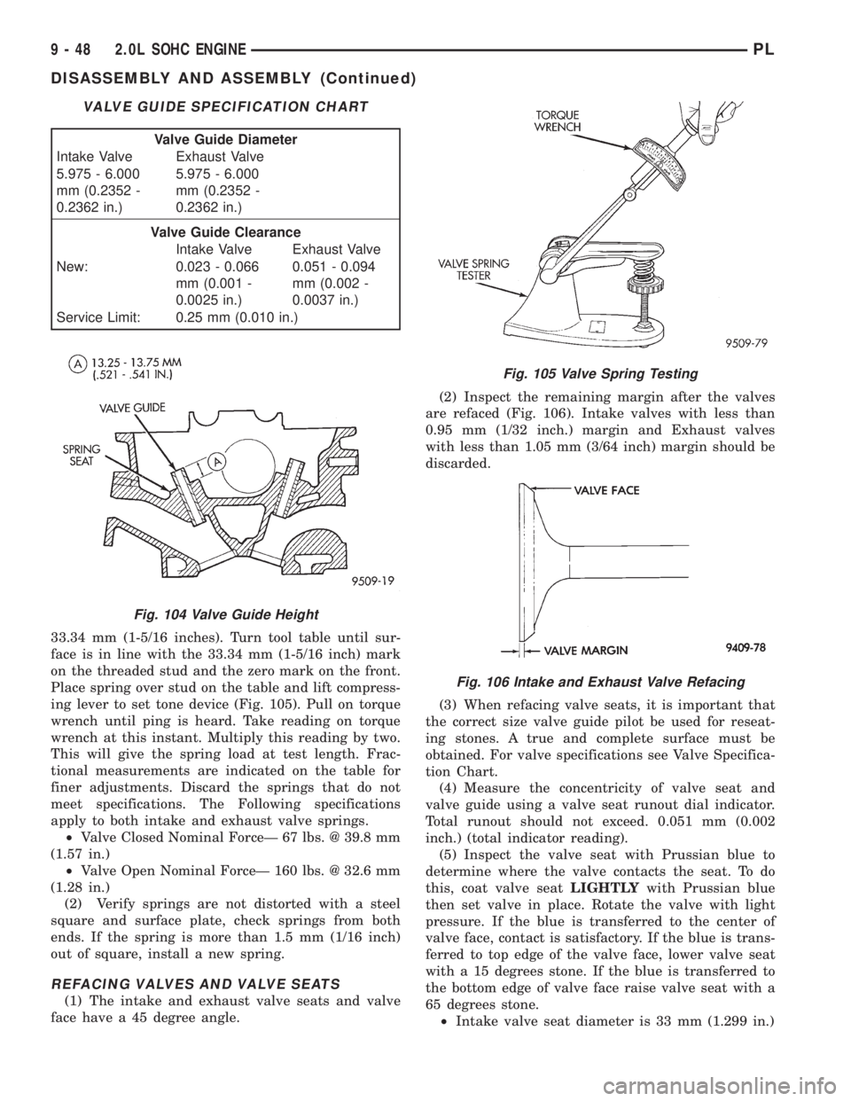
33.34 mm (1-5/16 inches). Turn tool table until sur-
face is in line with the 33.34 mm (1-5/16 inch) mark
on the threaded stud and the zero mark on the front.
Place spring over stud on the table and lift compress-
ing lever to set tone device (Fig. 105). Pull on torque
wrench until ping is heard. Take reading on torque
wrench at this instant. Multiply this reading by two.
This will give the spring load at test length. Frac-
tional measurements are indicated on the table for
finer adjustments. Discard the springs that do not
meet specifications. The Following specifications
apply to both intake and exhaust valve springs.
²Valve Closed Nominal ForceÐ 67 lbs. @ 39.8 mm
(1.57 in.)
²Valve Open Nominal ForceÐ 160 lbs. @ 32.6 mm
(1.28 in.)
(2) Verify springs are not distorted with a steel
square and surface plate, check springs from both
ends. If the spring is more than 1.5 mm (1/16 inch)
out of square, install a new spring.
REFACING VALVES AND VALVE SEATS
(1) The intake and exhaust valve seats and valve
face have a 45 degree angle.(2) Inspect the remaining margin after the valves
are refaced (Fig. 106). Intake valves with less than
0.95 mm (1/32 inch.) margin and Exhaust valves
with less than 1.05 mm (3/64 inch) margin should be
discarded.
(3) When refacing valve seats, it is important that
the correct size valve guide pilot be used for reseat-
ing stones. A true and complete surface must be
obtained. For valve specifications see Valve Specifica-
tion Chart.
(4) Measure the concentricity of valve seat and
valve guide using a valve seat runout dial indicator.
Total runout should not exceed. 0.051 mm (0.002
inch.) (total indicator reading).
(5) Inspect the valve seat with Prussian blue to
determine where the valve contacts the seat. To do
this, coat valve seatLIGHTLYwith Prussian blue
then set valve in place. Rotate the valve with light
pressure. If the blue is transferred to the center of
valve face, contact is satisfactory. If the blue is trans-
ferred to top edge of the valve face, lower valve seat
with a 15 degrees stone. If the blue is transferred to
the bottom edge of valve face raise valve seat with a
65 degrees stone.
²Intake valve seat diameter is 33 mm (1.299 in.)
VALVE GUIDE SPECIFICATION CHART
Valve Guide Diameter
Intake Valve Exhaust Valve
5.975 - 6.000
mm (0.2352 -
0.2362 in.)5.975 - 6.000
mm (0.2352 -
0.2362 in.)
Valve Guide Clearance
Intake Valve Exhaust Valve
New: 0.023 - 0.066
mm (0.001 -
0.0025 in.)0.051 - 0.094
mm (0.002 -
0.0037 in.)
Service Limit: 0.25 mm (0.010 in.)
Fig. 104 Valve Guide Height
Fig. 105 Valve Spring Testing
Fig. 106 Intake and Exhaust Valve Refacing
9 - 48 2.0L SOHC ENGINEPL
DISASSEMBLY AND ASSEMBLY (Continued)
Page 776 of 1200
CRANKSHAFT END PLAY
DIAL INDICATOR METHOD
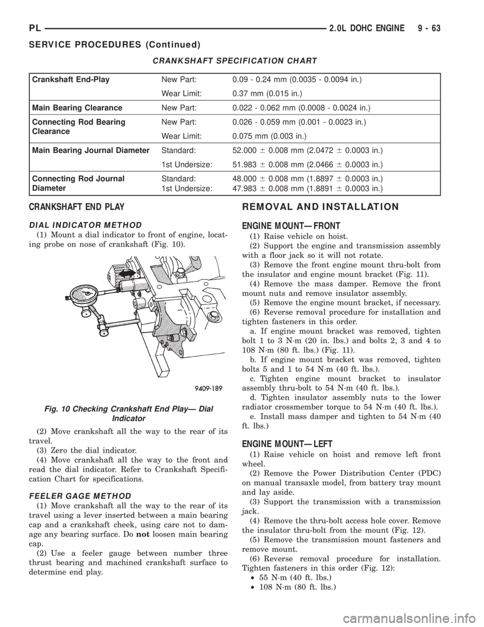
(1) Mount a dial indicator to front of engine, locat-
ing probe on nose of crankshaft (Fig. 10).
(2) Move crankshaft all the way to the rear of its
travel.
(3) Zero the dial indicator.
(4) Move crankshaft all the way to the front and
read the dial indicator. Refer to Crankshaft Specifi-
cation Chart for specifications.
FEELER GAGE METHOD
(1) Move crankshaft all the way to the rear of its
travel using a lever inserted between a main bearing
cap and a crankshaft cheek, using care not to dam-
age any bearing surface. Donotloosen main bearing
cap.
(2) Use a feeler gauge between number three
thrust bearing and machined crankshaft surface to
determine end play.
REMOVAL AND INSTALLATION
ENGINE MOUNTÐFRONT
(1) Raise vehicle on hoist.
(2) Support the engine and transmission assembly
with a floor jack so it will not rotate.
(3) Remove the front engine mount thru-bolt from
the insulator and engine mount bracket (Fig. 11).
(4) Remove the mass damper. Remove the front
mount nuts and remove insulator assembly.
(5) Remove the engine mount bracket, if necessary.
(6) Reverse removal procedure for installation and
tighten fasteners in this order.
a. If engine mount bracket was removed, tighten
bolt 1 to 3 N´m (20 in. lbs.) and bolts 2, 3 and 4 to
108 N´m (80 ft. lbs.) (Fig. 11).
b. If engine mount bracket was removed, tighten
bolts 5 and 1 to 54 N´m (40 ft. lbs.).
c. Tighten engine mount bracket to insulator
assembly thru-bolt to 54 N´m (40 ft. lbs.).
d. Tighten insulator assembly nuts to the lower
radiator crossmember torque to 54 N´m (40 ft. lbs.).
e. Install mass damper and tighten to 54 N´m (40
ft. lbs.)
ENGINE MOUNTÐLEFT
(1) Raise vehicle on hoist and remove left front
wheel.
(2) Remove the Power Distribution Center (PDC)
on manual transaxle model, from battery tray mount
and lay aside.
(3) Support the transmission with a transmission
jack.
(4) Remove the thru-bolt access hole cover. Remove
the insulator thru-bolt from the mount (Fig. 12).
(5) Remove the transmission mount fasteners and
remove mount.
(6) Reverse removal procedure for installation.
Tighten fasteners in this order (Fig. 12):
²55 N´m (40 ft. lbs.)
²108 N´m (80 ft. lbs.)
CRANKSHAFT SPECIFICATION CHART
Crankshaft End-PlayNew Part: 0.09 - 0.24 mm (0.0035 - 0.0094 in.)
Wear Limit: 0.37 mm (0.015 in.)
Main Bearing ClearanceNew Part: 0.022 - 0.062 mm (0.0008 - 0.0024 in.)
Connecting Rod Bearing
ClearanceNew Part: 0.026 - 0.059 mm (0.001 - 0.0023 in.)
Wear Limit: 0.075 mm (0.003 in.)
Main Bearing Journal DiameterStandard: 52.00060.008 mm (2.047260.0003 in.)
1st Undersize: 51.98360.008 mm (2.046660.0003 in.)
Connecting Rod Journal
DiameterStandard: 48.00060.008 mm (1.889760.0003 in.)
1st Undersize: 47.98360.008 mm (1.889160.0003 in.)
Fig. 10 Checking Crankshaft End PlayÐ Dial
Indicator
PL2.0L DOHC ENGINE 9 - 63
SERVICE PROCEDURES (Continued)
Page 805 of 1200
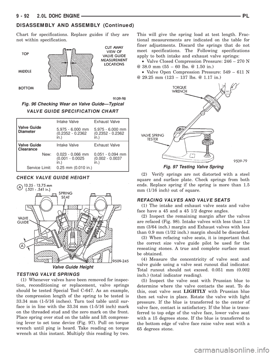
Chart for specifications. Replace guides if they are
not within specification.
CHECK VALVE GUIDE HEIGHT
TESTING VALVE SPRINGS
(1) Whenever valves have been removed for inspec-
tion, reconditioning or replacement, valve springs
should be tested Special Tool C-647. As an example,
the compression length of the spring to be tested is
33.34 mm (1-5/16 inches). Turn tool table until sur-
face is in line with the 33.34 mm (1-5/16 inch) mark
on the threaded stud and the zero mark on the front.
Place spring over stud on the table and lift compress-
ing lever to set tone device (Fig. 97). Pull on torque
wrench until ping is heard. Take reading on torque
wrench at this instant. Multiply this reading by two.This will give the spring load at test length. Frac-
tional measurements are indicated on the table for
finer adjustments. Discard the springs that do not
meet specifications. The Following specifications
apply to both intake and exhaust valve springs:
²Valve Closed Compression Pressure: 246 ± 270 N
@ 38.0 mm (55 ± 60 lbs. @ 1.50 in.)
²Valve Open Compression Pressure: 549 ± 611 N
@ 29.25 mm (123 ± 137 lbs. @ 1.17 in.)
(2) Verify springs are not distorted with a steel
square and surface plate. Check springs from both
ends. Replace spring if the spring is more than 1.5
mm (1/16 inch) out of square.
REFACING VALVES AND VALVE SEATS
(1) The intake and exhaust valve seats and valve
face have a 45 and a 45 1/2 degree angles.
(2) Inspect the remaining margin after the valves
are refaced (Fig. 98). Intake valves with less than 1.2
mm (3/64 inch.) margin and Exhaust valves with less
than 0.9 mm (1/32 inch.) margin should be discarded.
(3) When refacing valve seats, it is important that
the correct size valve guide pilot be used for the
reseating stones. A true and complete surface must
be obtained.
(4) Measure the concentricity of valve seat and
valve guide using a valve seat runout dial indicator.
Total runout should not exceed. 0.051 mm (0.002
inch.) (total indicator reading).
(5) Inspect the valve seat with Prussian blue to
determine where the valve contacts the seat. To do
this, coat valve seatLIGHTLYwith Prussian blue
then set valve in place. Rotate the valve with light
pressure. If the blue is transferred to the center of
valve face, contact is satisfactory. If the blue is trans-
ferred to top edge of the valve face, lower valve seat
with a 15 degrees stone. If the blue is transferred to
the bottom edge of valve face raise valve seat with a
65 degrees stone.
Fig. 96 Checking Wear on Valve GuideÐTypical
VALVE GUIDE SPECIFICATION CHART
Valve Guide
DiameterIntake Valve Exhaust Valve
5.975 - 6.000 mm
(0.2352 - 0.2362
in.)5.975 - 6.000 mm
(0.2352 - 0.2362
in.)
Valve Guide
ClearanceIntake Valve Exhaust Valve
New: 0.023 - 0.066 mm
(0.001 - 0.0025
in.)0.051 - 0.094 mm
(0.002 - 0.0037
in.)
Service Limit: 0.25 mm (0.010 in.)
Valve Guide Height
Fig. 97 Testing Valve Spring
9 - 92 2.0L DOHC ENGINEPL
DISASSEMBLY AND ASSEMBLY (Continued)
Page 875 of 1200
FUEL INJECTORSÐPCM OUTPUT
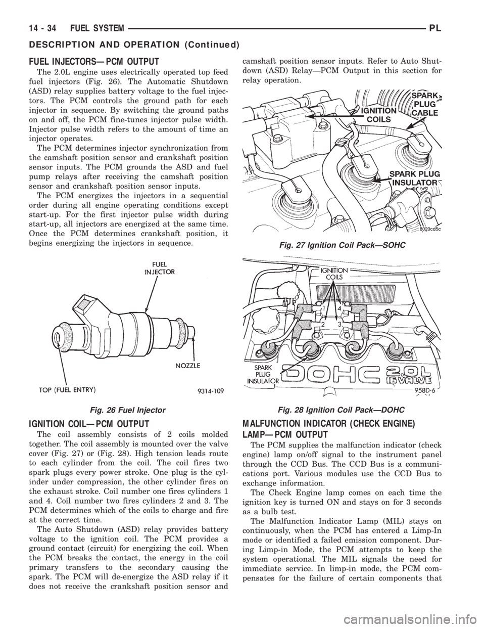
The 2.0L engine uses electrically operated top feed
fuel injectors (Fig. 26). The Automatic Shutdown
(ASD) relay supplies battery voltage to the fuel injec-
tors. The PCM controls the ground path for each
injector in sequence. By switching the ground paths
on and off, the PCM fine-tunes injector pulse width.
Injector pulse width refers to the amount of time an
injector operates.
The PCM determines injector synchronization from
the camshaft position sensor and crankshaft position
sensor inputs. The PCM grounds the ASD and fuel
pump relays after receiving the camshaft position
sensor and crankshaft position sensor inputs.
The PCM energizes the injectors in a sequential
order during all engine operating conditions except
start-up. For the first injector pulse width during
start-up, all injectors are energized at the same time.
Once the PCM determines crankshaft position, it
begins energizing the injectors in sequence.
IGNITION COILÐPCM OUTPUT
The coil assembly consists of 2 coils molded
together. The coil assembly is mounted over the valve
cover (Fig. 27) or (Fig. 28). High tension leads route
to each cylinder from the coil. The coil fires two
spark plugs every power stroke. One plug is the cyl-
inder under compression, the other cylinder fires on
the exhaust stroke. Coil number one fires cylinders 1
and 4. Coil number two fires cylinders 2 and 3. The
PCM determines which of the coils to charge and fire
at the correct time.
The Auto Shutdown (ASD) relay provides battery
voltage to the ignition coil. The PCM provides a
ground contact (circuit) for energizing the coil. When
the PCM breaks the contact, the energy in the coil
primary transfers to the secondary causing the
spark. The PCM will de-energize the ASD relay if it
does not receive the crankshaft position sensor andcamshaft position sensor inputs. Refer to Auto Shut-
down (ASD) RelayÐPCM Output in this section for
relay operation.
MALFUNCTION INDICATOR (CHECK ENGINE)
LAMPÐPCM OUTPUT
The PCM supplies the malfunction indicator (check
engine) lamp on/off signal to the instrument panel
through the CCD Bus. The CCD Bus is a communi-
cations port. Various modules use the CCD Bus to
exchange information.
The Check Engine lamp comes on each time the
ignition key is turned ON and stays on for 3 seconds
as a bulb test.
The Malfunction Indicator Lamp (MIL) stays on
continuously, when the PCM has entered a Limp-In
mode or identified a failed emission component. Dur-
ing Limp-in Mode, the PCM attempts to keep the
system operational. The MIL signals the need for
immediate service. In limp-in mode, the PCM com-
pensates for the failure of certain components that
Fig. 26 Fuel Injector
Fig. 27 Ignition Coil PackÐSOHC
Fig. 28 Ignition Coil PackÐDOHC
14 - 34 FUEL SYSTEMPL
DESCRIPTION AND OPERATION (Continued)
Page 971 of 1200
INSTALLATION
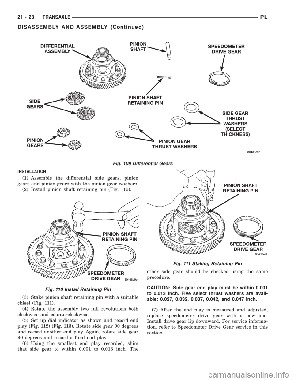
(1) Assemble the differential side gears, pinion
gears and pinion gears with the pinion gear washers.
(2) Install pinion shaft retaining pin (Fig. 110).
(3) Stake pinion shaft retaining pin with a suitable
chisel (Fig. 111).
(4) Rotate the assembly two full revolutions both
clockwise and counterclockwise.
(5) Set up dial indicator as shown and record end
play (Fig. 112) (Fig. 113). Rotate side gear 90 degrees
and record another end play. Again, rotate side gear
90 degrees and record a final end play.
(6) Using the smallest end play recorded, shim
that side gear to within 0.001 to 0.013 inch. Theother side gear should be checked using the same
procedure.
CAUTION: Side gear end play must be within 0.001
to 0.013 inch. Five select thrust washers are avail-
able: 0.027, 0.032, 0.037, 0.042, and 0.047 inch.
(7) After the end play is measured and adjusted,
replace speedometer drive gear with a new one.
Install drive gear lip downward. For service informa-
tion, refer to Speedometer Drive Gear service in this
section.
Fig. 109 Differential Gears
Fig. 110 Install Retaining Pin
Fig. 111 Staking Retaining Pin
21 - 28 TRANSAXLEPL
DISASSEMBLY AND ASSEMBLY (Continued)
Page 1002 of 1200
(6) If fluid flow is still found to be inadequate,
check the line pressure using the Transaxle Hydrau-
lic Pressure Test procedure.
REMOVAL AND INSTALLATION
GEARSHIFT CABLE
REMOVAL
(1) Disconnect both battery cables.
(2) Pull up and remove the power distribution cen-
ter.
(3) Remove the battery thermoguard.
(4) Remove the battery and battery holddown from
the battery tray.
(5) Remove the battery tray and cruise control
servo (if equipped).
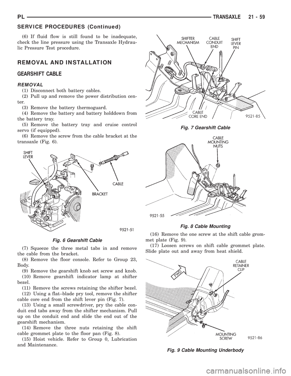
(6) Remove the screw from the cable bracket at the
transaxle (Fig. 6).
(7) Squeeze the three metal tabs in and remove
the cable from the bracket.
(8) Remove the floor console. Refer to Group 23,
Body.
(9) Remove the gearshift knob set screw and knob.
(10) Remove gearshift indicator lamp at shifter
bezel.
(11) Remove the screws retaining the shifter bezel.
(12) Using a flat±blade pry tool, remove the shifter
cable core end from the shift lever pin (Fig. 7).
(13) Using a small screwdriver, pry the cable con-
duit end tabs away from the shifter mechanism. Pull
up on the conduit end and slide the end out of the
gearshift mechanism.
(14) Remove the three nuts retaining the shift
cable grommet plate to the floor pan (Fig. 8).
(15) Hoist vehicle. Refer to Group 0, Lubrication
and Maintenance.(16) Remove the one screw at the shift cable grom-
met plate (Fig. 9).
(17) Loosen screws on shift cable grommet plate.
Slide plate out and away from heat shield.
Fig. 6 Gearshift Cable
Fig. 7 Gearshift Cable
Fig. 8 Cable Mounting
Fig. 9 Cable Mounting Underbody
PLTRANSAXLE 21 - 59
SERVICE PROCEDURES (Continued)