1999 DODGE NEON torque
[x] Cancel search: torquePage 35 of 1200
INSTALL
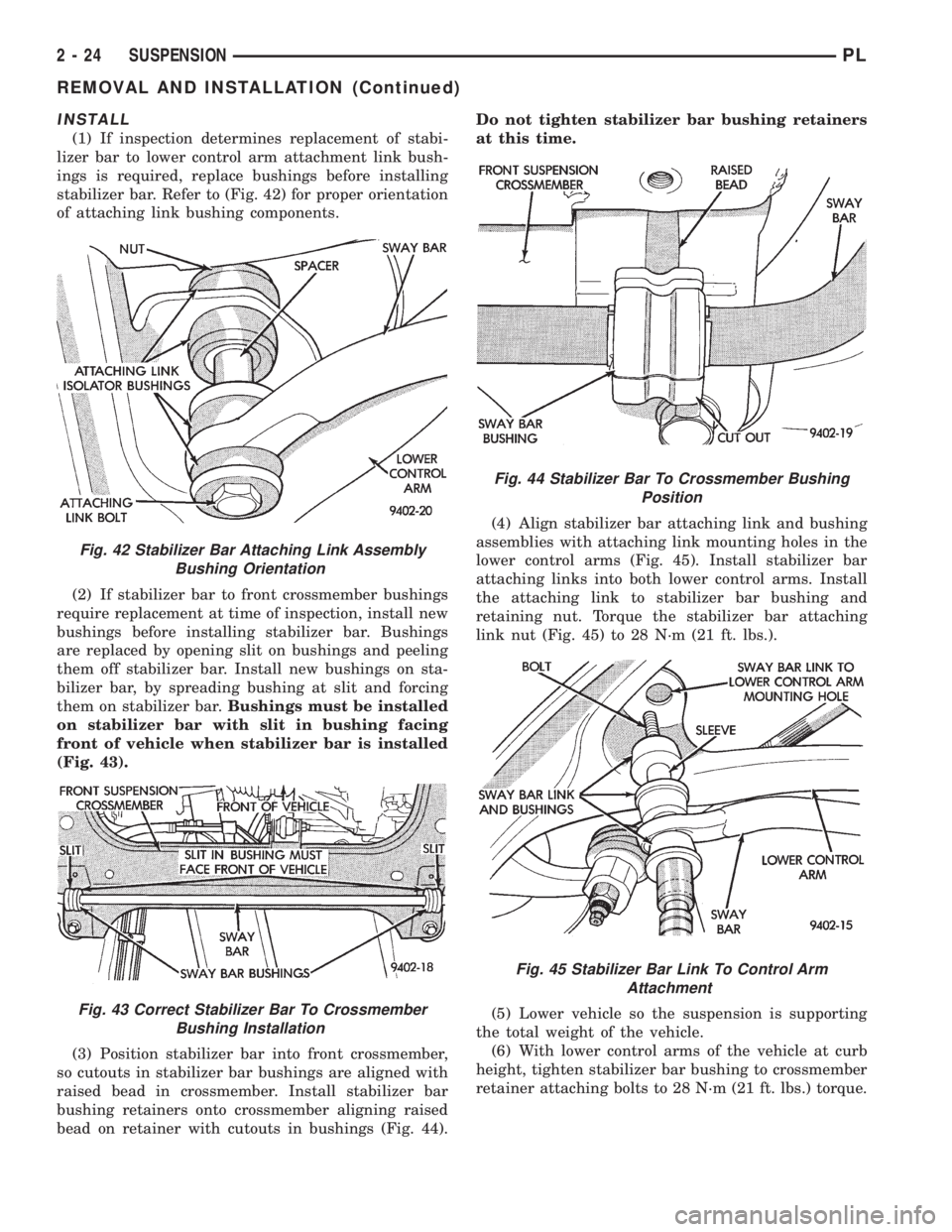
(1) If inspection determines replacement of stabi-
lizer bar to lower control arm attachment link bush-
ings is required, replace bushings before installing
stabilizer bar. Refer to (Fig. 42) for proper orientation
of attaching link bushing components.
(2) If stabilizer bar to front crossmember bushings
require replacement at time of inspection, install new
bushings before installing stabilizer bar. Bushings
are replaced by opening slit on bushings and peeling
them off stabilizer bar. Install new bushings on sta-
bilizer bar, by spreading bushing at slit and forcing
them on stabilizer bar.Bushings must be installed
on stabilizer bar with slit in bushing facing
front of vehicle when stabilizer bar is installed
(Fig. 43).
(3) Position stabilizer bar into front crossmember,
so cutouts in stabilizer bar bushings are aligned with
raised bead in crossmember. Install stabilizer bar
bushing retainers onto crossmember aligning raised
bead on retainer with cutouts in bushings (Fig. 44).Do not tighten stabilizer bar bushing retainers
at this time.
(4) Align stabilizer bar attaching link and bushing
assemblies with attaching link mounting holes in the
lower control arms (Fig. 45). Install stabilizer bar
attaching links into both lower control arms. Install
the attaching link to stabilizer bar bushing and
retaining nut. Torque the stabilizer bar attaching
link nut (Fig. 45) to 28 N´m (21 ft. lbs.).
(5) Lower vehicle so the suspension is supporting
the total weight of the vehicle.
(6) With lower control arms of the vehicle at curb
height, tighten stabilizer bar bushing to crossmember
retainer attaching bolts to 28 N´m (21 ft. lbs.) torque.
Fig. 42 Stabilizer Bar Attaching Link Assembly
Bushing Orientation
Fig. 43 Correct Stabilizer Bar To Crossmember
Bushing Installation
Fig. 44 Stabilizer Bar To Crossmember Bushing
Position
Fig. 45 Stabilizer Bar Link To Control Arm
Attachment
2 - 24 SUSPENSIONPL
REMOVAL AND INSTALLATION (Continued)
Page 38 of 1200
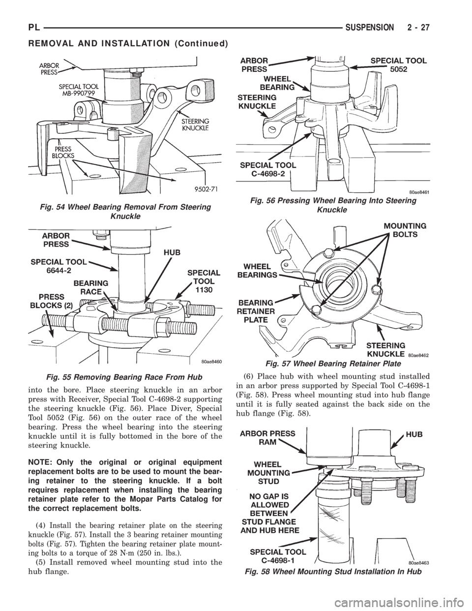
into the bore. Place steering knuckle in an arbor
press with Receiver, Special Tool C-4698-2 supporting
the steering knuckle (Fig. 56). Place Diver, Special
Tool 5052 (Fig. 56) on the outer race of the wheel
bearing. Press the wheel bearing into the steering
knuckle until it is fully bottomed in the bore of the
steering knuckle.
NOTE: Only the original or original equipment
replacement bolts are to be used to mount the bear-
ing retainer to the steering knuckle. If a bolt
requires replacement when installing the bearing
retainer plate refer to the Mopar Parts Catalog for
the correct replacement bolts.
(4)
Install the bearing retainer plate on the steering
knuckle (Fig. 57). Install the 3 bearing retainer mounting
bolts (Fig. 57). Tighten the bearing retainer plate mount-
ing bolts to a torque of 28 N´m (250 in. lbs.).
(5) Install removed wheel mounting stud into the
hub flange.(6) Place hub with wheel mounting stud installed
in an arbor press supported by Special Tool C-4698-1
(Fig. 58). Press wheel mounting stud into hub flange
until it is fully seated against the back side on the
hub flange (Fig. 58).
Fig. 58 Wheel Mounting Stud Installation In Hub
Fig. 54 Wheel Bearing Removal From Steering
Knuckle
Fig. 55 Removing Bearing Race From Hub
Fig. 56 Pressing Wheel Bearing Into Steering
Knuckle
Fig. 57 Wheel Bearing Retainer Plate
PLSUSPENSION 2 - 27
REMOVAL AND INSTALLATION (Continued)
Page 41 of 1200
(5) Install the disc brake caliper to steering
knuckle attaching bolts (Fig. 61). Tighten the attach-
ing bolts to a torque of 31 N´m (23 ft. lbs.).
(6) Install front wheel and tire. Install front wheel
lug nuts and torque to 135 N´m
(7) (100 ft. lbs.).
(8) Lower vehicle.
DISASSEMBLY AND ASSEMBLY
McPHERSON STRUT
DISASSEMBLY
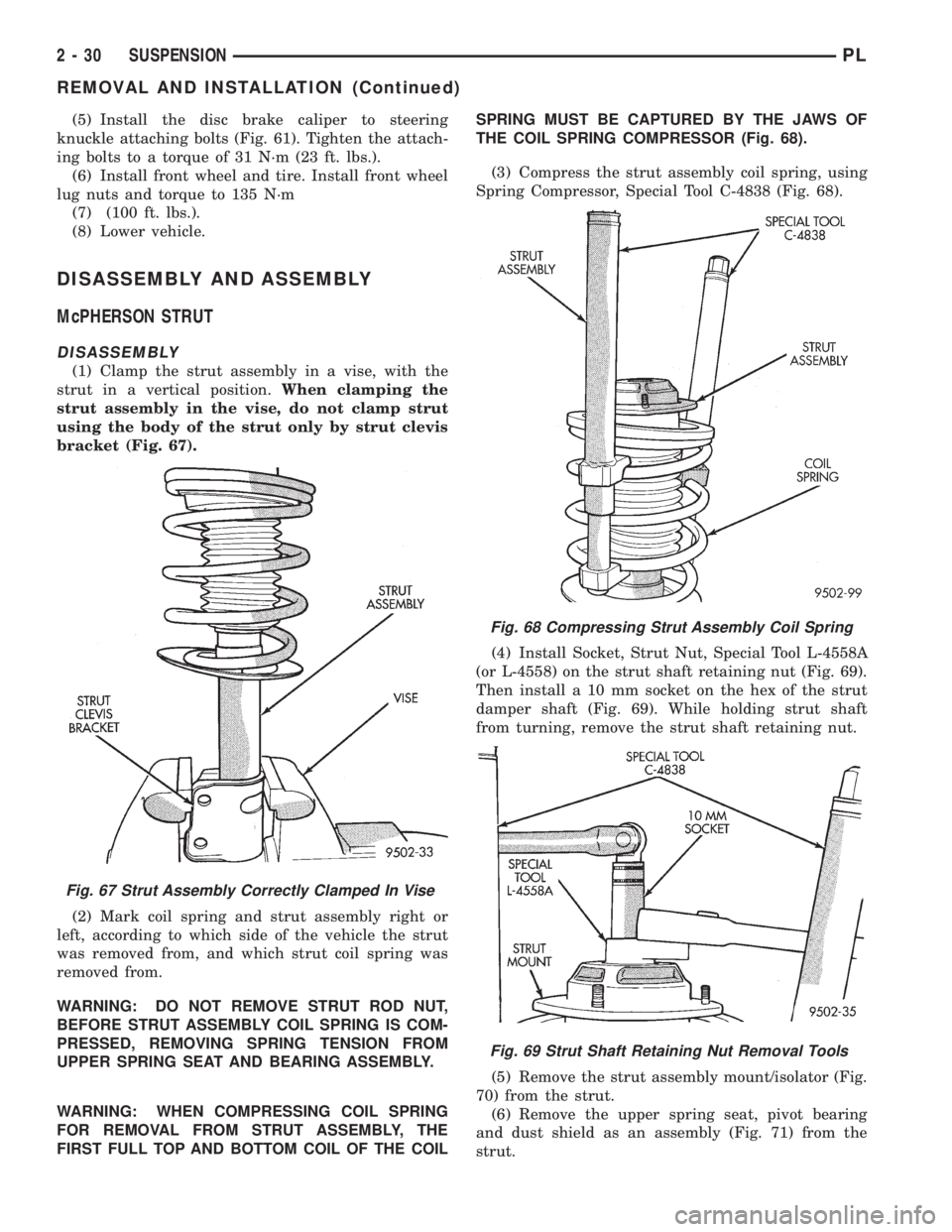
(1) Clamp the strut assembly in a vise, with the
strut in a vertical position.When clamping the
strut assembly in the vise, do not clamp strut
using the body of the strut only by strut clevis
bracket (Fig. 67).
(2) Mark coil spring and strut assembly right or
left, according to which side of the vehicle the strut
was removed from, and which strut coil spring was
removed from.
WARNING: DO NOT REMOVE STRUT ROD NUT,
BEFORE STRUT ASSEMBLY COIL SPRING IS COM-
PRESSED, REMOVING SPRING TENSION FROM
UPPER SPRING SEAT AND BEARING ASSEMBLY.
WARNING: WHEN COMPRESSING COIL SPRING
FOR REMOVAL FROM STRUT ASSEMBLY, THE
FIRST FULL TOP AND BOTTOM COIL OF THE COILSPRING MUST BE CAPTURED BY THE JAWS OF
THE COIL SPRING COMPRESSOR (Fig. 68).
(3) Compress the strut assembly coil spring, using
Spring Compressor, Special Tool C-4838 (Fig. 68).
(4) Install Socket, Strut Nut, Special Tool L-4558A
(or L-4558) on the strut shaft retaining nut (Fig. 69).
Then install a 10 mm socket on the hex of the strut
damper shaft (Fig. 69). While holding strut shaft
from turning, remove the strut shaft retaining nut.
(5) Remove the strut assembly mount/isolator (Fig.
70) from the strut.
(6) Remove the upper spring seat, pivot bearing
and dust shield as an assembly (Fig. 71) from the
strut.
Fig. 67 Strut Assembly Correctly Clamped In Vise
Fig. 68 Compressing Strut Assembly Coil Spring
Fig. 69 Strut Shaft Retaining Nut Removal Tools
2 - 30 SUSPENSIONPL
REMOVAL AND INSTALLATION (Continued)
Page 43 of 1200

²Binding strut assembly pivot bearing. If pivot
bearing is replaced it is to be installed with the white
side of bearing facing up (Fig. 74).
²Inspect dust shield for rips and/or deterioration.
²Inspect jounce bumper for cracks and signs of
deterioration.
(11) Replace any components of the strut assembly
found to be worn or defective during the inspection,
before assembling the strut.
ASSEMBLE
(1) Clamp the strut assembly in a vise, with the
strut in a vertical position.When clamping the
strut assembly in the vise, do not clamp strut
using the body of the strut only by strut clevis
bracket (Fig. 67).
(2) Install the compressed coil spring onto the
strut. Coil spring is to be installed with smaller coil
down, so spring correctly seats on strut assembly
(Fig. 73).
(3) Install jounce bumper on the strut shaft (Fig.
72).
(4) Install dust shield, pivot bearing and upper
spring seat as an assembly on the strut (Fig. 71).
(5) Position upper spring seat alignment notch
with clevis bracket on strut assembly.
(6) Install strut mount on strut assembly (Fig. 70)
and the strut mount retaining nut on the shaft of the
strut assembly.
WARNING: THE FOLLOWING 2 STEPS MUST BE
COMPLETELY DONE BEFORE SPRING COMPRES-
SOR, SPECIAL TOOL C-4838 IS RELEASED FROM
THE COIL SPRING.
(7) Install Socket, Strut Nut, Special Tool L-4558A
(or L-4558) on the strut shaft retaining nut (Fig. 69).
Then install a 10 mm socket through the center of
the socket and on the hex of the strut shaft (Fig. 69).
While holding strut shaft from turning, torque strut
shaft retaining nut to 75 N´m (55 ft. lbs.).
(8) Equally loosen both Spring Compressors, Spe-
cial Tool C-4838 until top coil of spring is fully seated
against upper spring seat and strut mount. Then
relieve all tension from spring compressors and
remove spring compressors from strut assembly
spring.
BALL JOINT
DISASSEMBLE
(1) Using a screw driver or other suitable tool, pry
seal boot off of ball joint assembly (Fig. 75).
(2) Position Receiving Cup, Special Tool 6758 to
support lower control arm while receiving ball joint
assembly (Fig. 76). Install Remover/Installer, Special
Tool 6804 in top of ball joint assembly (Fig. 76).(3) Using arbor press, press ball joint assembly
completely out of lower control arm.
ASSEMBLE
CAUTION: When installing ball joint in its mount-
ing hole in lower control arm, position ball joint so
notch in ball joint stud is facing the front lower con-
trol arm bushing. This will ease assembly of ball
joint to steering knuckle when attempting to install
pinch bolt.
(1) By hand, position ball joint assembly into ball
joint bore of lower control arm. Be sure ball joint
assembly is not cocked in the bore of the control arm,
this will cause binding of the ball joint assembly,
when being pressed into lower control arm.
(2) Position assembly in an arbor press with
Receiving Cup, Special Tool 6758 supporting lower
control arm (Fig. 77). Then install Remover/Installer,
Special Tool 6804 on the bottom of the ball joint
assembly (Fig. 77).
Fig. 75 Ball Joint Seal Boot Removal
Fig. 76 Removing Ball Joint From Lower Control
Arm
2 - 32 SUSPENSIONPL
DISASSEMBLY AND ASSEMBLY (Continued)
Page 47 of 1200
ADJUSTMENTS
STRUT ADJUSTMENT COMPETITION PACKAGE
SUSPENSION
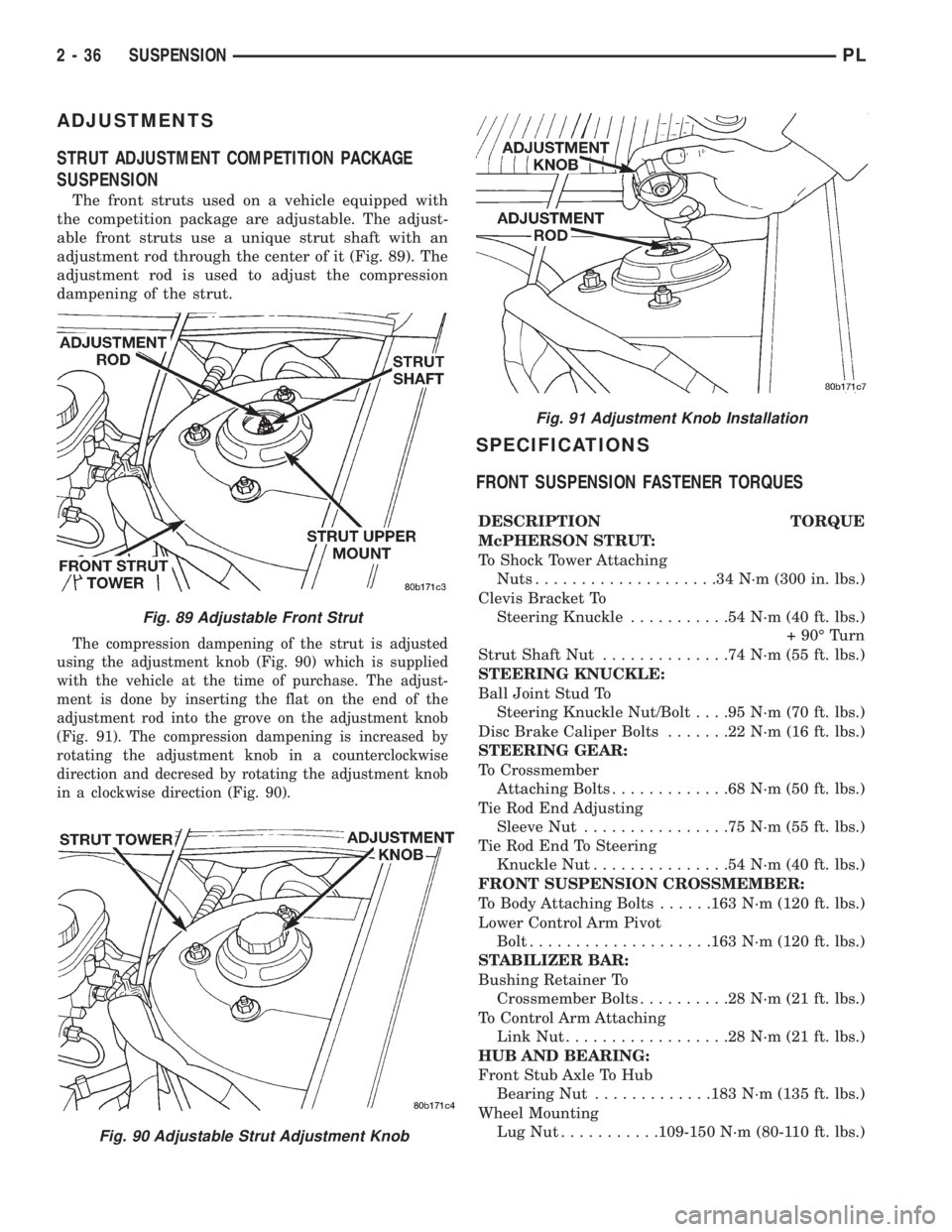
The front struts used on a vehicle equipped with
the competition package are adjustable. The adjust-
able front struts use a unique strut shaft with an
adjustment rod through the center of it (Fig. 89). The
adjustment rod is used to adjust the compression
dampening of the strut.
The compression dampening of the strut is adjusted
using the adjustment knob (Fig. 90) which is supplied
with the vehicle at the time of purchase. The adjust-
ment is done by inserting the flat on the end of the
adjustment rod into the grove on the adjustment knob
(Fig. 91). The compression dampening is increased by
rotating the adjustment knob in a counterclockwise
direction and decresed by rotating the adjustment knob
in a clockwise direction (Fig. 90).
SPECIFICATIONS
FRONT SUSPENSION FASTENER TORQUES
DESCRIPTION TORQUE
McPHERSON STRUT:
To Shock Tower Attaching
Nuts....................34N´m(300 in. lbs.)
Clevis Bracket To
Steering Knuckle...........54N´m(40ft.lbs.)
+ 90É Turn
Strut Shaft Nut..............74N´m(55ft.lbs.)
STEERING KNUCKLE:
Ball Joint Stud To
Steering Knuckle Nut/Bolt. . . .95 N´m (70 ft. lbs.)
Disc Brake Caliper Bolts.......22N´m(16ft.lbs.)
STEERING GEAR:
To Crossmember
Attaching Bolts.............68N´m(50ft.lbs.)
Tie Rod End Adjusting
Sleeve Nut................75N´m(55ft.lbs.)
Tie Rod End To Steering
Knuckle Nut...............54N´m(40ft.lbs.)
FRONT SUSPENSION CROSSMEMBER:
To Body Attaching Bolts......163 N´m (120 ft. lbs.)
Lower Control Arm Pivot
Bolt....................163 N´m (120 ft. lbs.)
STABILIZER BAR:
Bushing Retainer To
Crossmember Bolts..........28N´m(21ft.lbs.)
To Control Arm Attaching
Link Nut..................28N´m(21ft.lbs.)
HUB AND BEARING:
Front Stub Axle To Hub
Bearing Nut.............183 N´m (135 ft. lbs.)
Wheel Mounting
LugNut...........109-150 N´m (80-110 ft. lbs.)
Fig. 89 Adjustable Front Strut
Fig. 90 Adjustable Strut Adjustment Knob
Fig. 91 Adjustment Knob Installation
2 - 36 SUSPENSIONPL
Page 50 of 1200
REAR SUSPENSION
INDEX
page page
GENERAL INFORMATION
GENERAL INFORMATION................. 39
DESCRIPTION AND OPERATION
COIL SPRING........................... 41
COMPETITION PACKAGE SUSPENSION...... 41
KNUCKLE............................. 41
LATERAL LINKS AND TENSION STRUTS...... 41
REAR SUSPENSION..................... 39
STABILIZER BAR........................ 41
STRUT................................ 41
DIAGNOSIS AND TESTING
KNUCKLE............................. 42
LATERAL LINKS......................... 42
STABILIZER BAR AND BUSHINGS........... 43
STABILIZER BAR ATTACHING LINKS......... 43
STRUT INSPECTION (ON VEHICLE)......... 42
TENSION STRUT........................ 42
SERVICE PROCEDURES
REAR WHEEL ALIGNMENT................ 43REMOVAL AND INSTALLATION
COIL SPRING........................... 44
KNUCKLE............................. 46
LATERAL LINKS......................... 48
STABILIZER BAR........................ 45
STRUT ASSEMBLY...................... 43
DISASSEMBLY AND ASSEMBLY
STABILIZER BAR BUSHINGS............... 53
STRUT ASSEMBLY...................... 50
ADJUSTMENTS
STRUT ADJUSTMENT COMPETITION
PACKAGE SUSPENSION................ 53
SPECIFICATIONS
REAR SUSPENSION FASTENER TORQUE
SPECIFICATIONS...................... 54
SPECIAL TOOLS
REAR SUSPENSION..................... 54
GENERAL INFORMATION
GENERAL INFORMATION
CAUTION: Only frame contact or wheel lift hoisting
equipment can be used on vehicles having a fully
independent rear suspension. Vehicles with inde-
pendent rear suspension can not be hoisted using
equipment designed to lift a vehicle by the rear
axle. If this type of hoisting equipment is used dam-
age to rear suspension components will occur.
NOTE: If a rear suspension component becomes
bent, damaged or fails, no attempt should be made
to straighten or repair it. Always replace with a new
component.
DESCRIPTION AND OPERATION
REAR SUSPENSION
The rear suspension system used on this vehicle is
a fully independent type rear suspension system (Fig.
1).A forged rear knuckle is bolted to each rear strut.
The movement of the rear knuckle is controlled lat-
erally using lateral links going from the front and
rear of the knuckle to the rear crossmember. Fore
and aft movement of the knuckle is controlled by a
tension strut.
The lateral links and tension strut have rubber iso-
lator bushings at each end. The lateral links are
attached to the rear crossmember and knuckle, using
a common bolt and nut assembly at each end. The
tension strut bolts to the bottom of the knuckle and
to a bracket attached to the floor pan of the vehicle.
The lateral links, tension strut and spindle are
normally replaced only when the part has been dam-
aged or when the vehicle has been involved in an
accident. If a suspension part has been damaged, be
sure to check the underbody dimensions of the car. If
the underbody dimensions are not correct, the frame
of the vehicle must be straightened, before replace-
ment suspension components are installed.
PLSUSPENSION 2 - 39
Page 52 of 1200
COMPETITION PACKAGE SUSPENSION
On vehicles that are equipped with the optional
competition package, special rear struts are used.
The rear struts used on a vehicle equipped with
the competition package are adjustable. The adjust-
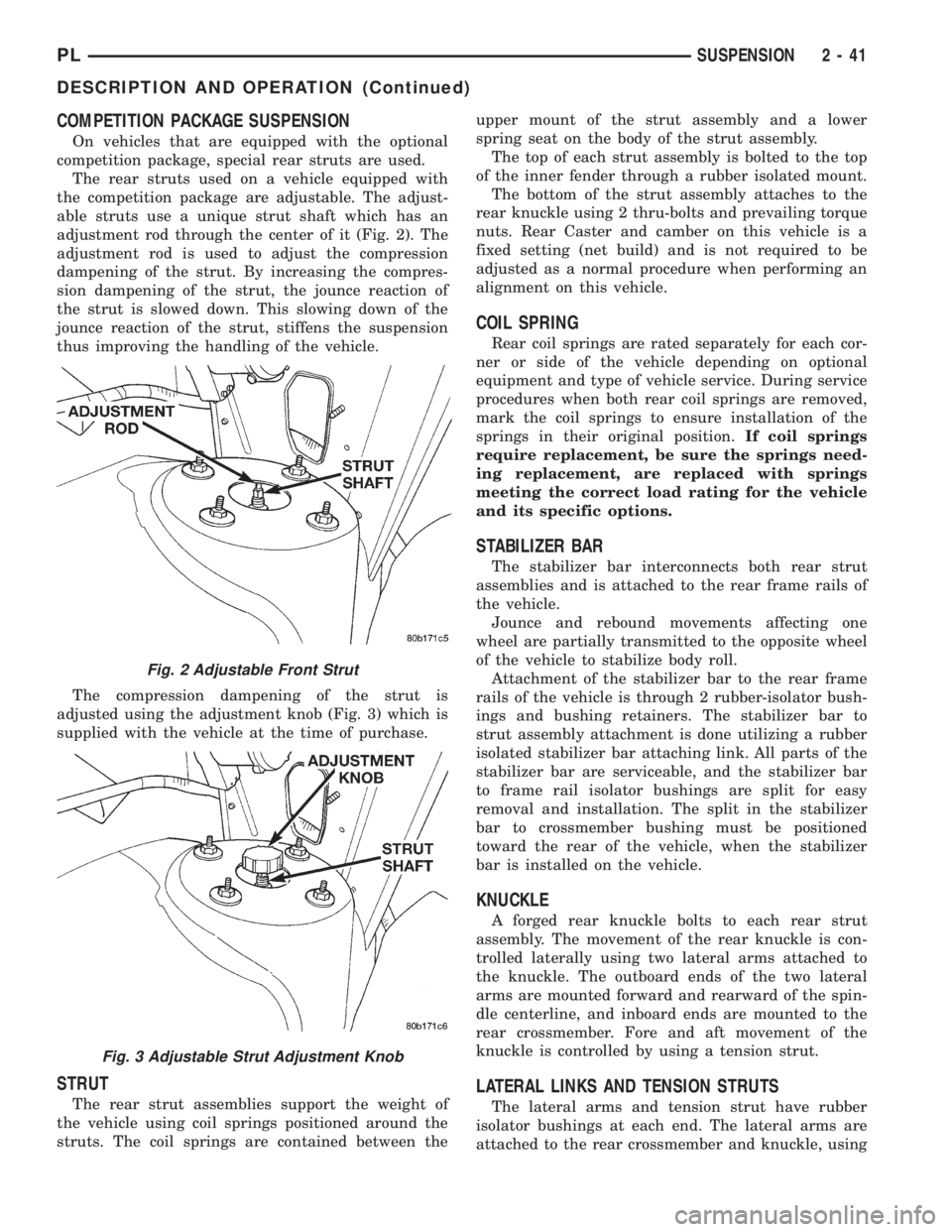
able struts use a unique strut shaft which has an
adjustment rod through the center of it (Fig. 2). The
adjustment rod is used to adjust the compression
dampening of the strut. By increasing the compres-
sion dampening of the strut, the jounce reaction of
the strut is slowed down. This slowing down of the
jounce reaction of the strut, stiffens the suspension
thus improving the handling of the vehicle.
The compression dampening of the strut is
adjusted using the adjustment knob (Fig. 3) which is
supplied with the vehicle at the time of purchase.
STRUT
The rear strut assemblies support the weight of
the vehicle using coil springs positioned around the
struts. The coil springs are contained between theupper mount of the strut assembly and a lower
spring seat on the body of the strut assembly.
The top of each strut assembly is bolted to the top
of the inner fender through a rubber isolated mount.
The bottom of the strut assembly attaches to the
rear knuckle using 2 thru-bolts and prevailing torque
nuts. Rear Caster and camber on this vehicle is a
fixed setting (net build) and is not required to be
adjusted as a normal procedure when performing an
alignment on this vehicle.
COIL SPRING
Rear coil springs are rated separately for each cor-
ner or side of the vehicle depending on optional
equipment and type of vehicle service. During service
procedures when both rear coil springs are removed,
mark the coil springs to ensure installation of the
springs in their original position.If coil springs
require replacement, be sure the springs need-
ing replacement, are replaced with springs
meeting the correct load rating for the vehicle
and its specific options.
STABILIZER BAR
The stabilizer bar interconnects both rear strut
assemblies and is attached to the rear frame rails of
the vehicle.
Jounce and rebound movements affecting one
wheel are partially transmitted to the opposite wheel
of the vehicle to stabilize body roll.
Attachment of the stabilizer bar to the rear frame
rails of the vehicle is through 2 rubber-isolator bush-
ings and bushing retainers. The stabilizer bar to
strut assembly attachment is done utilizing a rubber
isolated stabilizer bar attaching link. All parts of the
stabilizer bar are serviceable, and the stabilizer bar
to frame rail isolator bushings are split for easy
removal and installation. The split in the stabilizer
bar to crossmember bushing must be positioned
toward the rear of the vehicle, when the stabilizer
bar is installed on the vehicle.
KNUCKLE
A forged rear knuckle bolts to each rear strut
assembly. The movement of the rear knuckle is con-
trolled laterally using two lateral arms attached to
the knuckle. The outboard ends of the two lateral
arms are mounted forward and rearward of the spin-
dle centerline, and inboard ends are mounted to the
rear crossmember. Fore and aft movement of the
knuckle is controlled by using a tension strut.
LATERAL LINKS AND TENSION STRUTS
The lateral arms and tension strut have rubber
isolator bushings at each end. The lateral arms are
attached to the rear crossmember and knuckle, using
Fig. 2 Adjustable Front Strut
Fig. 3 Adjustable Strut Adjustment Knob
PLSUSPENSION 2 - 41
DESCRIPTION AND OPERATION (Continued)
Page 55 of 1200

(7) Remove carpet (if required) from top of strut
tower. Then remove rubber dust shield (Fig. 8) from
top of strut tower, this will allow easier access to
upper strut mount attaching nuts.
(8) Loosen but do not remove the 4 upper strut
mount to strut tower attaching nuts (Fig. 9). Then
while supporting the strut assembly fully remove the
4 strut mount attaching nuts.
(9) Remove strut assembly from knuckle, by slid-
ing knuckle out of clevis bracket on strut assembly.
Then remove strut assembly from vehicle.
INSTALL
(1) Position strut assembly back into vehicle with
the 4 studs on strut mount assembly through holes
in strut tower of vehicle. Install the 4 strut mount to
body attaching nuts (Fig. 9) onto mount studs.
Torque the 4 strut mount to body attaching nuts to
34 N´m (300 in. lbs).(2) Install dust shield into hole on top of strut
tower (Fig. 8). Install carpeting back on top of rear
strut tower.
(3) Raise vehicle.
CAUTION: The knuckle to strut assembly attaching
bolts are serrated and must not be turned during
installation. Install and torque nuts while holding
bolts stationary in knuckle.
(4) Install knuckle assembly into clevis bracket on
strut assembly. Install the 2 clevis bracket to knuckle
assembly attaching bolts and nuts (Fig. 7). Torque
both clevis bracket to knuckle assembly attaching
nuts to 95 N´m (70 ft. lbs.).
(5) Install hydraulic flex hose bracket, on strut
assembly bracket (Fig. 6). Install and securely
tighten bolt attaching hose bracket to strut bracket.
If vehicle is equipped with Anti-Lock brakes, the
wheel speed sensor cable routing clip is also attached
to the strut assembly bracket.
(6) Install wheel and tire assembly on vehicle.
Tighten the wheel mounting stud nuts in proper
sequence until all nuts are torqued to half specifica-
tion. Then repeat tightening sequence to full speci-
fied torque of 135 N´m (100 ft. lbs.).
(7) Lower vehicle to the ground.
(8) Check and reset rear wheel TOE to specifica-
tions if required. Refer to Front And Rear Toe Setting
Procedure in the Wheel Alignment Check And
Adjustment section in this group of the service man-
ual for the required Toe setting procedure.
COIL SPRING
Coil springs are rated separately for each side of
vehicle depending on optional equipment and type of
service. During service procedures where both
springs are removed, mark springs (Chalk, Tape,
etc.) (Fig. 10) to ensure installation in original posi-
tion. If the coils springs require replacement.Be
sure that the springs needing replacement, are
replaced with springs meeting the correct load
and spring rate for the vehicle.
NOTE: During service procedures requiring
removal or installation of a coil spring with Spring
Compressor, Special Tool C-4838. It is required that
the first full top and bottom coil of the coil spring
be captured by the jaws of spring compressor (Fig.
10).
Replacement of the coil spring requires removal of
the strut assembly from the vehicle, and the disas-
sembly of the strut. Refer to strut assembly in the
removal and installation section in this group of the
service manual for the required removal and replace-
ment procedure for the strut assembly. Then refer to
Fig. 8 Dust Shield Removal From Strut Tower
Fig. 9 Strut Mount Attaching Nuts
2 - 44 SUSPENSIONPL
REMOVAL AND INSTALLATION (Continued)