Page 25 of 64
.
Dual pipe gas-pressure shock absorber
The dual pipe gas-pressure shock absorber
has become established as the standard
damper.
In the dual pipe gas-pressure")
25
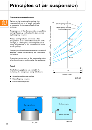
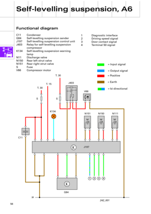
Shock absorbers (vibration
dampers).
Dual pipe gas-pressure shock absorber
The dual pipe gas-pressure shock absorber
has become established as the standard
damper.
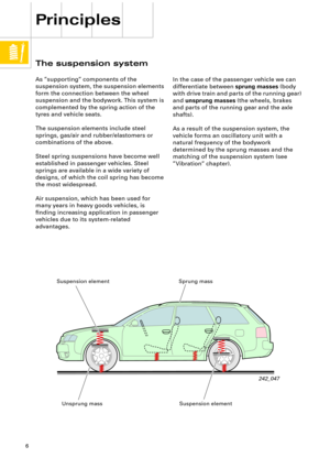
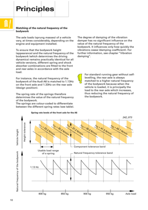
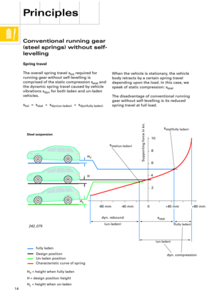
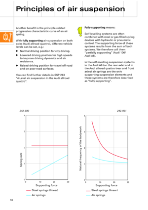
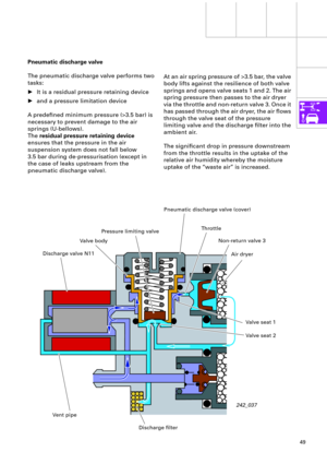
In the dual pipe gas-pressure shock absorber,
the working cylinder and the housing form
two chambers. The piston and piston rod
move inside the working chamber, which is
completely Þlled with hydraulic oil. The ring-
shaped oil reservoir between the working
cylinder and the housing serves to
compensate volumetric changes caused by
the piston rods and temperature changes in
the hydraulic oil.
The oil reservoir is only partially Þlled with oil
and is under a pressure of 6 - 8 bar, which
reduces the tendency towards cavitation.
Two damping valve units are used for
damping; the piston valve and the bottom
valve. These comprise a system of spring
washers, coil springs and valve bodies with
throttle bores.
242_080
Cavitation is the formation cavities and
the creation of a vacuum in a rapid
liquid ßow.
Working cylinder
Gas Þlling
Damping valve unit
(piston valve)
Damping valve unit
(bottom valve)
Oil reservoir
Damper valve
Non-return valve
Page 26 of 64
26
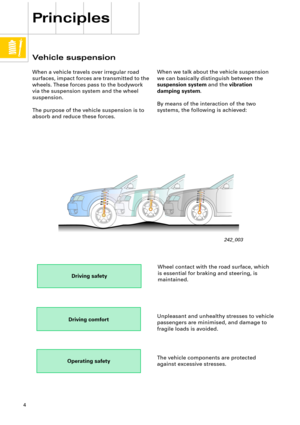
Principles of air suspension
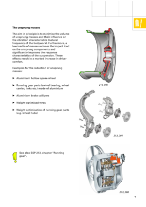
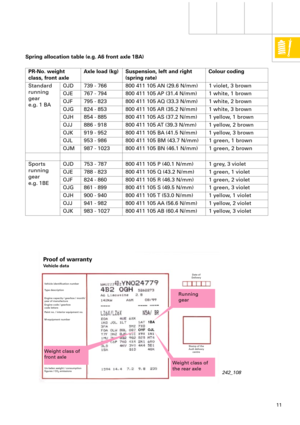
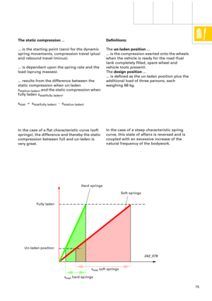
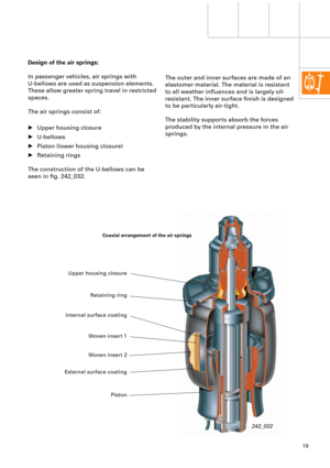
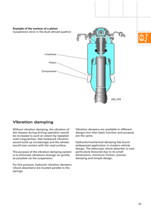
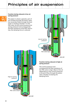
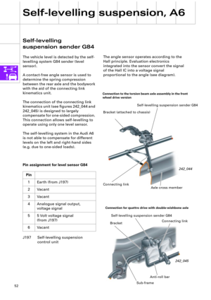
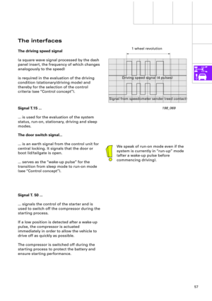
During rebound, the piston valve alone
carries out the damping action and exerts a
predetermined resistance against the oil
ßowing downwards.
The oil required in the working chamber can
ßow back unhindered via the non-return valve
in the bottom valve. Function
During compression, damping is determined
by the bottom valve and to a certain extent by
the return ßow resistance of the piston.
The oil displaced by the piston rod ßows into
the oil reservoir. The bottom valve exerts a
deÞned resistance against this ßow, thereby
braking the movement.
242_081
Rebound Compression
Bottom valve
Oil reservoir
Piston valve
Damper valve
Non-return valve
Page 27 of 64

27
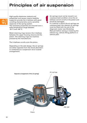
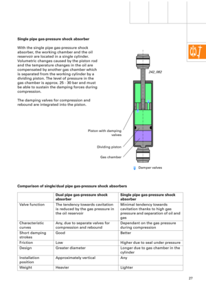
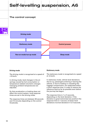
Single pipe gas-pressure shock absorber
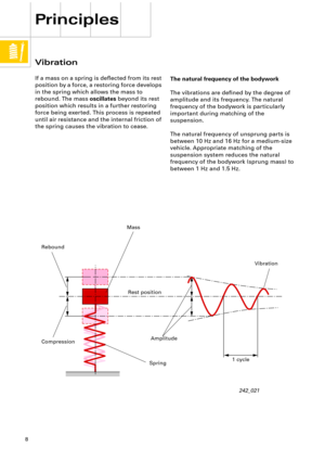
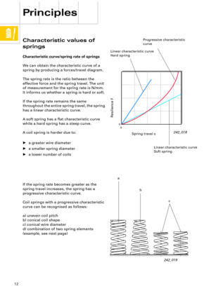
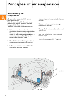
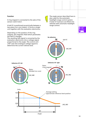
With the single pipe gas-pressure shock
absorber, the working chamber and the oil
reservoir are located in a single cylinder.
Volumetric changes caused by the piston rod
and the temperature changes in the oil are
compensated by another gas chamber which
is separated from the working cylinder by a
dividing piston. The level of pressure in the
gas chamber is approx. 25 - 30 bar and must
be able to sustain the damping forces during
compression.
The damping valves for compression and
rebound are integrated into the piston.
Comparison of single/dual pipe gas-pressure shock absorbers
Dual pipe gas-pressure shock
absorberSingle pipe gas-pressure shock
absorber
Valve function The tendency towards cavitation
is reduced by the gas pressure in
the oil reservoirMinimal tendency towards
cavitation thanks to high gas
pressure and separation of oil and
gas
Characteristic
curvesAny, due to separate valves for
compression and reboundDependant on the gas pressure
during compression
Short damping
strokesGood Better
Friction Low Higher due to seal under pressure
Design Greater diameter Longer due to gas chamber in the
cylinder
Installation
positionApproximately vertical Any
Weight Heavier Lighter
242_082
Piston with damping
valves
Dividing piston
Gas chamber
Damper valves
Page 28 of 64
28
Principles of air suspension
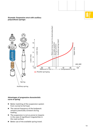
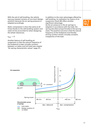
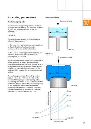
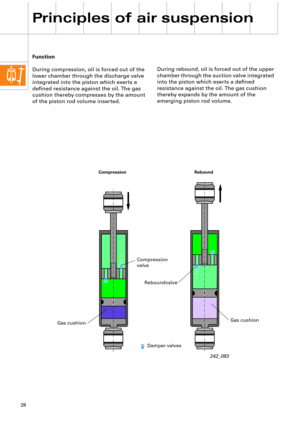
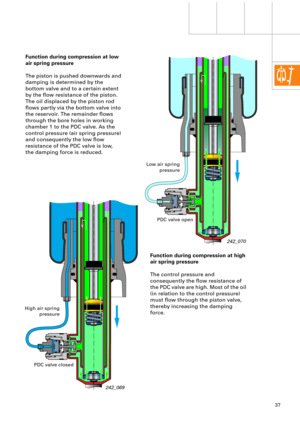
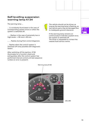
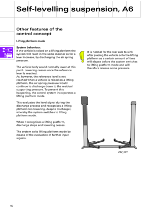
During rebound, oil is forced out of the upper
chamber through the suction valve integrated
into the piston which exerts a deÞned
resistance against the oil. The gas cushion
thereby expands by the amount of the
emerging piston rod volume. Function
During compression, oil is forced out of the
lower chamber through the discharge valve
integrated into the piston which exerts a
deÞned resistance against the oil. The gas
cushion thereby compresses by the amount
of the piston rod volume inserted.
242_083
Rebound Compression
Gas cushion
Reboundvalve
Compression
valve
Gas cushion
Damper valves
Page 29 of 64
29
0,13 0 0 200 400 600 800 1000
1200 1400 1600
0,26
0,390,520,650,78 0,91 1,04
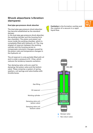
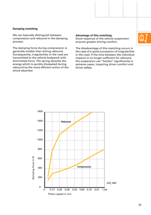
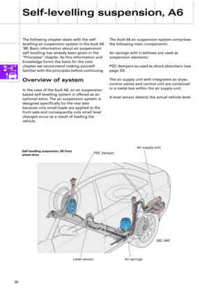
Advantage of this matching:
Good response of the vehicle suspension
ensures greater driving comfort.
The disadvantage of this matching occurs in
the case of a quick succession of irregularities
in the road. If the time between the individual
impacts is no longer sufÞcient for rebound,
the suspension can ÒhardenÓ signiÞcantly in
extreme cases, impairing driver comfort and
driver safety. Damping matching
We can basically distinguish between
compression and rebound in the damping
process.
The damping force during compression is
generally smaller than during rebound.
Consequently, irregularities in the road are
transmitted to the vehicle bodywork with
diminished force. The spring absorbs the
energy which is quickly dissipated during
rebound by the more efÞcient action of the
shock absorber.
242_084
Piston speed in m/s
Damping force in N
Compression Rebound
Page 30 of 64
30
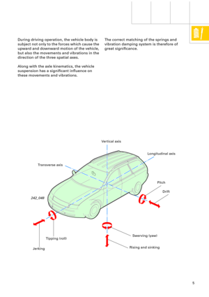
Principles of air suspension
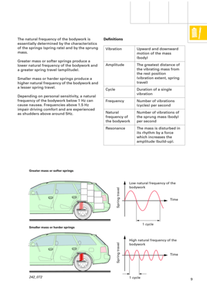
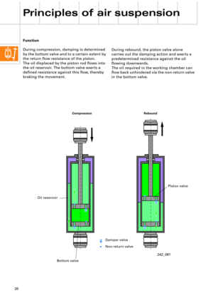
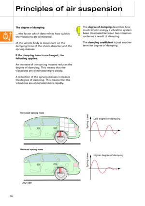
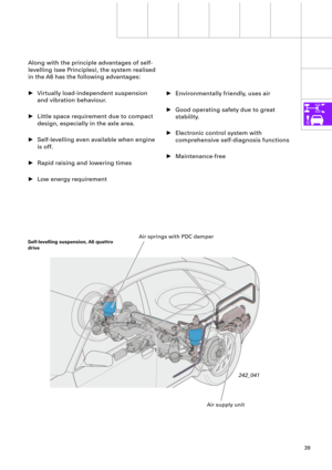
The degree of damping
... (the factor which determines how quickly
the vibrations are eliminated)
of the vehicle body is dependant on the
damping force of the shock absorber and the
sprung masses.
If the damping force is unchanged, the
following applies:
An increase of the sprung masses reduces the
degree of damping. This means that the
vibrations are eliminated more slowly.
A reduction of the sprung masses increases
the degree of damping. This means that the
vibrations are eliminated more rapidly.The degree of damping describes how
much kinetic energy a vibration system
been dissipated between two vibration
cycles as a result of damping.
The damping coefÞcient is just another
term for degree of damping.
242_068
Increased sprung mass
Reduced sprung mass
Spring travel Spring travel
Low degree of damping
Higher degree of damping
Page 31 of 64
.
These characteristic curve")
31
0,52 0,260
-0,26-0,52
0,52 0,260
-0,26-0,52
0,52 0,260
-0,26-0,52
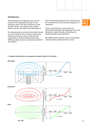
The force/stroke diagrams thus obtained can
be converted into force/velocity diagrams (f-v
diagrams).
These characteristic curves show the
relationship between the damping force and
the piston speed, thereby indicating the
shock absorber characteristics.
We differentiate between linear, progressive
and decreasing characteristic curves. Damping force
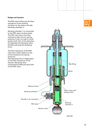
The damping force depends upon the oil
volume to be displaced (surface of the
damping valve), the ßow resistance of the
damper valves, the speed of the damper
piston and the viscosity of the damping oil.
The damping force is determined with the aid
of a test machine. At a constant speed, this
machine produces various rebound and
compression strokes thereby producing
differing rebound and compression speeds in
the damper.
242_066
F-v diagram characteristic curve progressions (speed constant for all strokes)
decreasing
progressive
linear
Traction
force
Compression
force
Traction
force
Compression
force
Traction
force
Compression
force
v in m/s
v in m/s
v in m/s 25 mm
50 mm
75 mm
100 mm
Stroke
Page 32 of 64
32
Principles of air suspension
Measures are taken during the design stage
to adapt the characteristic curves to the
requirements of suspension matching.
Shock absorbers with decreasing
characteristic curves are normally used.
Normal shock absorbers have predetermined
characteristic curves. They are adapted to
normal bodywork weights and can cope with
a wide range of driving situations in a well-
matched running gear.
Running gear matching is always a
compromise between driving safety (driving
dynamics) and driving comfort.
The degree of damping (damping effect of
sprung masses) is lessened as the load
increases, which affects the driving dynamics.
In contrast, the degree of damping is greater
when the vehicle is un-laden, which lessens
driving comfort.Note:
A distinctive feature of damper
matching is described in SSP 213,
page 28, ÒShock absorbers with load
and travel-dependent damping
characteristicsÓ.


of the vehicle body is dependant on the
damping force of the shock")
