Page 25 of 64

25
Shock absorbers (vibration
dampers).
Dual pipe gas-pressure shock absorber
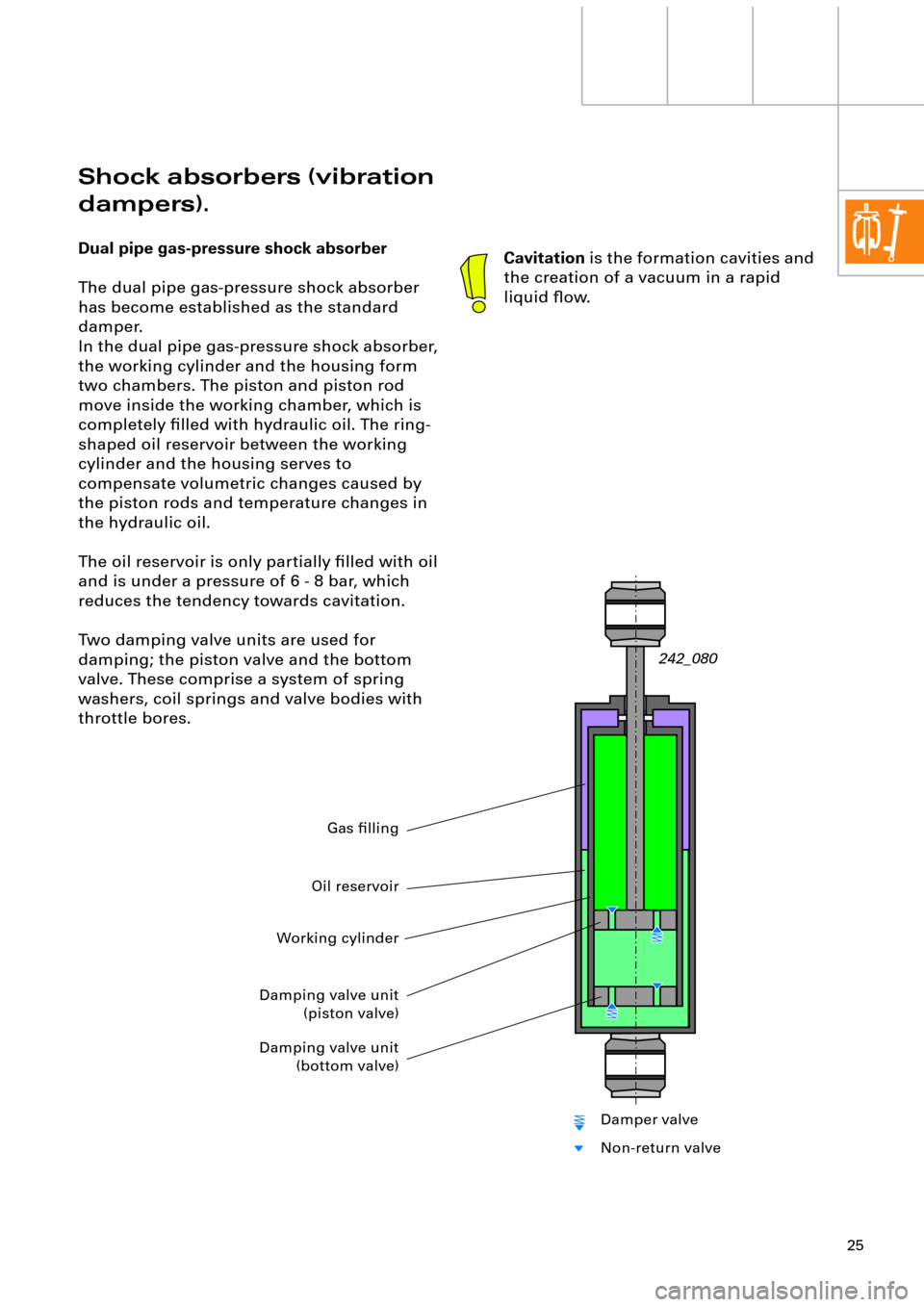
The dual pipe gas-pressure shock absorber
has become established as the standard
damper.
In the dual pipe gas-pressure shock absorber,
the working cylinder and the housing form
two chambers. The piston and piston rod
move inside the working chamber, which is
completely Þlled with hydraulic oil. The ring-
shaped oil reservoir between the working
cylinder and the housing serves to
compensate volumetric changes caused by
the piston rods and temperature changes in
the hydraulic oil.
The oil reservoir is only partially Þlled with oil
and is under a pressure of 6 - 8 bar, which
reduces the tendency towards cavitation.
Two damping valve units are used for
damping; the piston valve and the bottom
valve. These comprise a system of spring
washers, coil springs and valve bodies with
throttle bores.
242_080
Cavitation is the formation cavities and
the creation of a vacuum in a rapid
liquid ßow.
Working cylinder
Gas Þlling
Damping valve unit
(piston valve)
Damping valve unit
(bottom valve)
Oil reservoir
Damper valve
Non-return valve
Page 27 of 64

27
Single pipe gas-pressure shock absorber
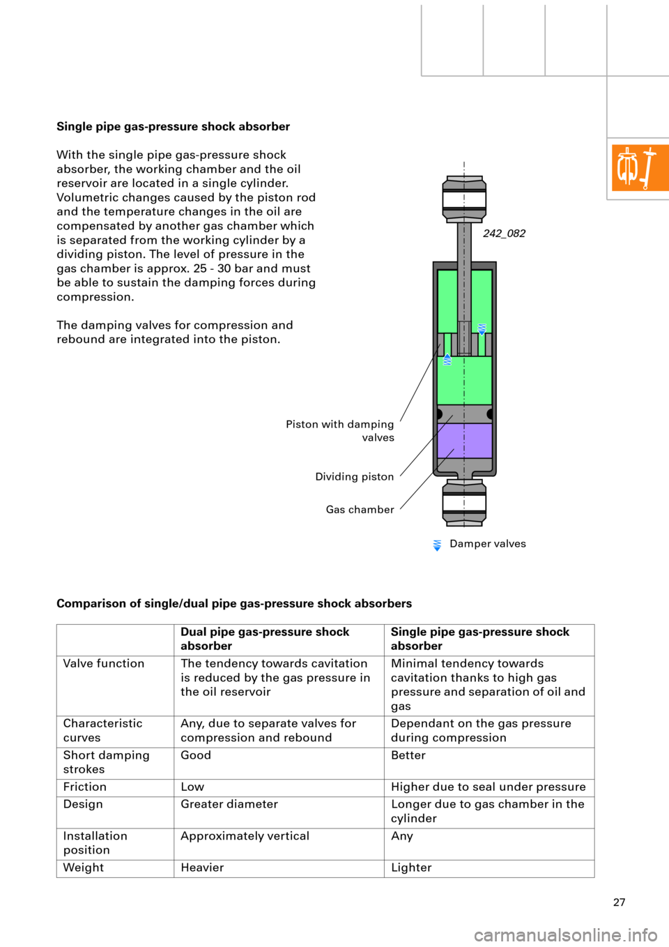
With the single pipe gas-pressure shock
absorber, the working chamber and the oil
reservoir are located in a single cylinder.
Volumetric changes caused by the piston rod
and the temperature changes in the oil are
compensated by another gas chamber which
is separated from the working cylinder by a
dividing piston. The level of pressure in the
gas chamber is approx. 25 - 30 bar and must
be able to sustain the damping forces during
compression.
The damping valves for compression and
rebound are integrated into the piston.
Comparison of single/dual pipe gas-pressure shock absorbers
Dual pipe gas-pressure shock
absorberSingle pipe gas-pressure shock
absorber
Valve function The tendency towards cavitation
is reduced by the gas pressure in
the oil reservoirMinimal tendency towards
cavitation thanks to high gas
pressure and separation of oil and
gas
Characteristic
curvesAny, due to separate valves for
compression and reboundDependant on the gas pressure
during compression
Short damping
strokesGood Better
Friction Low Higher due to seal under pressure
Design Greater diameter Longer due to gas chamber in the
cylinder
Installation
positionApproximately vertical Any
Weight Heavier Lighter
242_082
Piston with damping
valves
Dividing piston
Gas chamber
Damper valves
Page 44 of 64
44
Self-levelling suspension, A6
The compressor
The compressed air is generated by means of
a single stage piston compressor with
integrated air dryer. In order to avoid oil
contamination of the U-bellows and the dryer
cartridge, the compressor is a so-called dry
running compressor.
Permanently lubricated bearings and a PTFE
(polytetraßuoroethylene) piston ring ensure a
long service life.The discharge valve N111 and the pneumatic
discharge valve are integrated into the dryer
cartridge housing.
In order to protect the compressor from
overheating, it switches off at excess
temperatures (see Overheating protection
chapter, page 61).
Discharge valve N11Pneumatic discharge valve
with pressure limiting valve
Non-return valve 3Air dryer
Non-return valve 1
PTFE piston ring
Suction Þlter
Discharge Þlter
Pressure connector
242_013
Non-return valve 2
Page 47 of 64
47
The air dryer
The air must be dehumidiÞed in order to
prevent condensate and the associated
problems of corrosion and freezing. The
system used here is a so-called regenerative
air dryer system. A synthetically
manufactured silicate granulate is used as the
drying agent. This granulate can, depending
on the temperature, store up to 20% of its
own weight in water.
As the air dryer operates regeneratively, and
is only operated with oil-free, Þltered air, it is
not subject to replacement intervals and is
therefore maintenance-free.Because the air dryer is regenerated
only with waste air, the compressor
cannot be used to Þll any other
components. As this compressed air is
not fed back via the air dryer, no
regeneration can take place. For this
reason, the manufacturers do not Þt a
pressure connection for external
components.
Water/moisture in the system indicates
a fault in the air dryer or the system.
242_056 Granulate Þlling