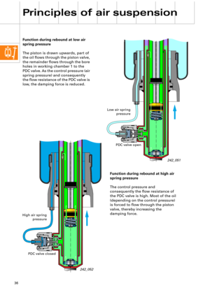
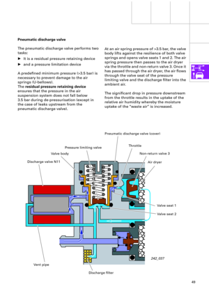
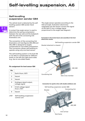
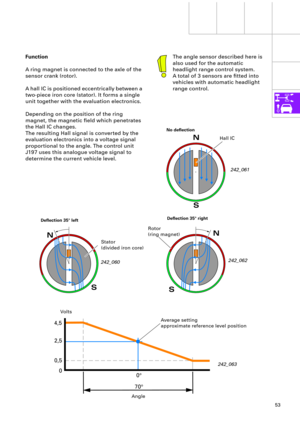
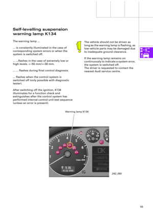
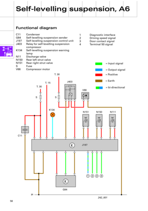
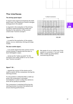
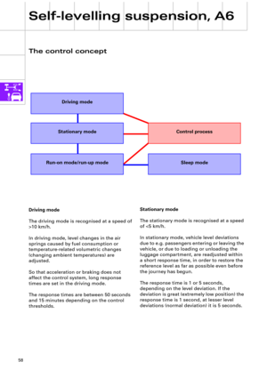
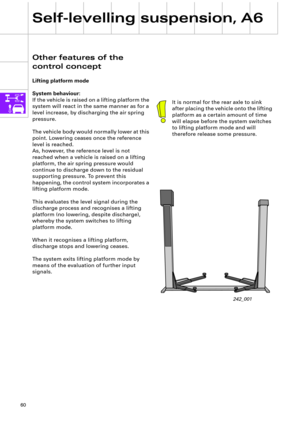
Page 9 of 64
 and by the sprung
mass.
Greater mass or softer springs produce a
lower natu")
9
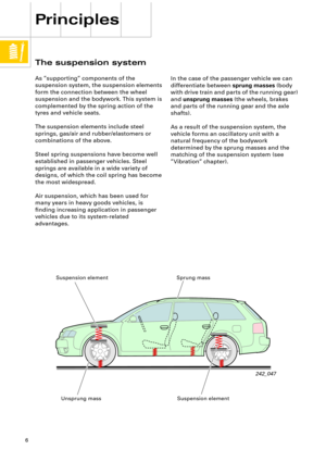
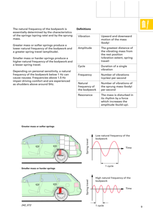
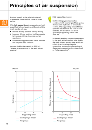
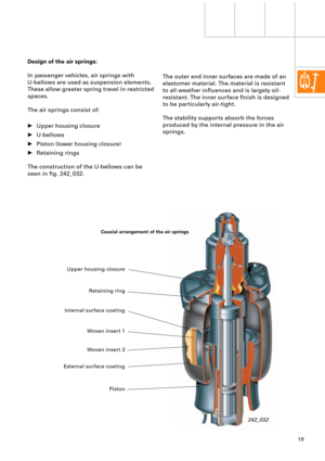
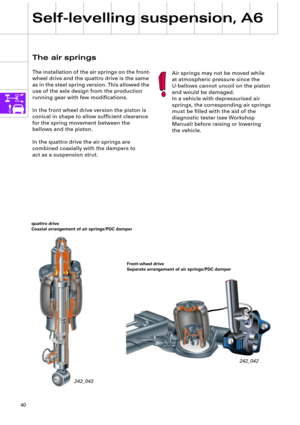
The natural frequency of the bodywork is
essentially determined by the characteristics
of the springs (spring rate) and by the sprung
mass.
Greater mass or softer springs produce a
lower natural frequency of the bodywork and
a greater spring travel (amplitude).
Smaller mass or harder springs produce a
higher natural frequency of the bodywork and
a lesser spring travel.
Depending on personal sensitivity, a natural
frequency of the bodywork below 1 Hz can
cause nausea. Frequencies above 1.5 Hz
impair driving comfort and are experienced
as shudders above around 5Hz.
242_072
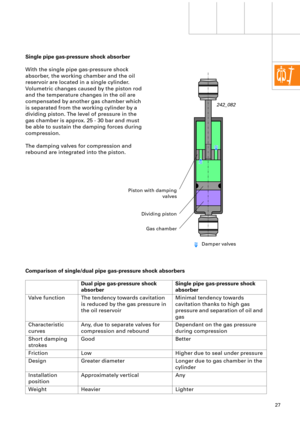
DeÞnitions
Vibration Upward and downward
motion of the mass
(body)
Amplitude The greatest distance of
the vibrating mass from
the rest position
(vibration extent, spring
travel)
Cycle Duration of a single
vibration
Frequency Number of vibrations
(cycles) per second
Natural
frequency of
the bodyworkNumber of vibrations of
the sprung mass (body)
per second
Resonance The mass is disturbed in
its rhythm by a force
which increases the
amplitude (build-up).
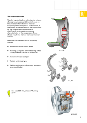
Greater mass or softer springs
Smaller mass or harder springs
Spring travel Spring travel
Low natural frequency of the
bodywork
High natural frequency of the
bodywork1 cycle
1 cycleTime
Time
Page 10 of 64

10
The degree of damping of the vibration
damper has no signiÞcant inßuence on the
value of the natural frequency of the
bodywork. It inßuences only how quickly the
vibrations cease (damping coefÞcient). For
further information, see chapter ÒVibration
dampingÓ.
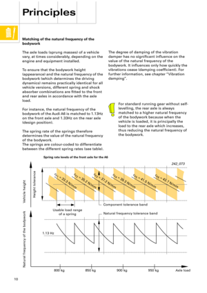
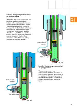
Matching of the natural frequency of the
bodywork
The axle loads (sprung masses) of a vehicle
vary, at times considerably, depending on the
engine and equipment installed.
To ensure that the bodywork height
(appearance) and the natural frequency of the
bodywork (which determines the driving
dynamics) remains practically identical for all
vehicle versions, different spring and shock
absorber combinations are Þtted to the front
and rear axles in accordance with the axle
load.
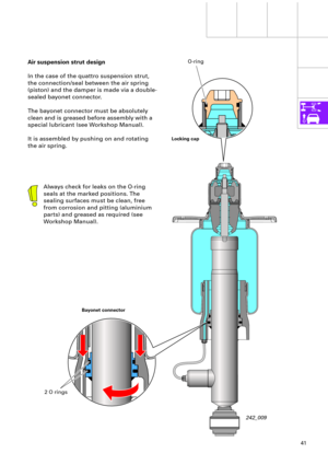
For instance, the natural frequency of the
bodywork of the Audi A6 is matched to 1.13Hz
on the front axle and 1.33Hz on the rear axle
(design position).
The spring rate of the springs therefore
determines the value of the natural frequency
of the bodywork.
The springs are colour-coded to differentiate
between the different spring rates (see table).
Principles
For standard running gear without self-
levelling, the rear axle is always
matched to a higher natural frequency
of the bodywork because when the
vehicle is loaded, it is principally the
load to the rear axle which increases,
thus reducing the natural frequency of
the bodywork.
242_073
Vehicle height Natural frequency of the bodyworkComponent tolerance band
Natural frequency tolerance band Usable load range
of a spring
Height tolerance
Axle load 800 kg 850 kg 900 kg 950 kg 1.13 Hz
c
F1
= 33.3 N/mmc
F2
= 35.2 N/mmc
F3
= 37.2 N/mmc
F4
= 39.3 N/mmc
F5
= 41.5 N/mmc
F6
= 43.7 N/mm
Spring rate levels of the front axle for the A6
Page 11 of 64

PR-No. weight
class, front axleAxle load (kg) Suspension, left and right
(spring rate)Colour coding
Standard
running
gear
e.g.")
11
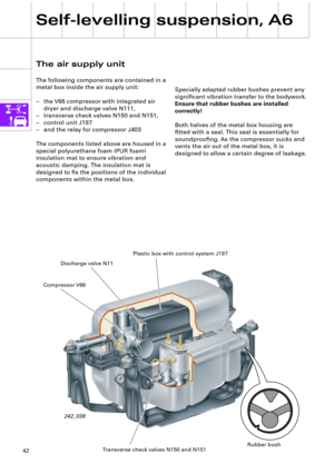
OJL1BA
OYF
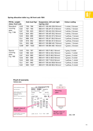
Spring allocation table (e.g. A6 front axle 1BA)
PR-No. weight
class, front axleAxle load (kg) Suspension, left and right
(spring rate)Colour coding
Standard
running
gear
e.g. 1 BAOJD 739 - 766 800 411 105 AN (29.6 N/mm) 1 violet, 3 brown
OJE 767 - 794 800 411 105 AP (31.4 N/mm) 1 white, 1 brown
OJF 795 - 823 800 411 105 AQ (33.3 N/mm) 1 white, 2 brown
OJG 824 - 853 800 411 105 AR (35.2 N/mm) 1 white, 3 brown
OJH 854 - 885 800 411 105 AS (37.2 N/mm) 1 yellow, 1 brown
OJJ 886 - 918 800 411 105 AT (39.3 N/mm) 1 yellow, 2 brown
OJK 919 - 952 800 411 105 BA (41.5 N/mm) 1 yellow, 3 brown
OJL 953 - 986 800 411 105 BM (43.7 N/mm) 1 green, 1 brown
OJM 987 - 1023 800 411 105 BN (46.1 N/mm) 1 green, 2 brown
Sports
running
gear
e.g. 1BEOJD 753 - 787 800 411 105 P (40.1 N/mm) 1 grey, 3 violet
OJE 788 - 823 800 411 105 Q (43.2 N/mm) 1 green, 1 violet
OJF 824 - 860 800 411 105 R (46.3 N/mm) 1 green, 2 violet
OJG 861 - 899 800 411 105 S (49.5 N/mm) 1 green, 3 violet
OJH 900 - 940 800 411 105 T (53.0 N/mm) 1 yellow, 1 violet
OJJ 941 - 982 800 411 105 AA (56.6 N/mm) 1 yellow, 2 violet
OJK 983 - 1027 800 411 105 AB (60.4 N/mm) 1 yellow, 3 violet
Weight class of
front axleRunning
gear
Weight class of
the rear axle
242_108
Proof of warranty
Vehicle data
Vehicle identiÞcation number
Type description
Engine capacity / gearbox / month/
year of manufacture
Engine code / gearbox
code letters
Paint no. / interior equipment no.
M-equipment number
Un-laden weight / consumption
Þgures / CO
2
emissionsDate of
Delivery
Stamp of the
Audi delivery
centre
Page 12 of 64

12
00
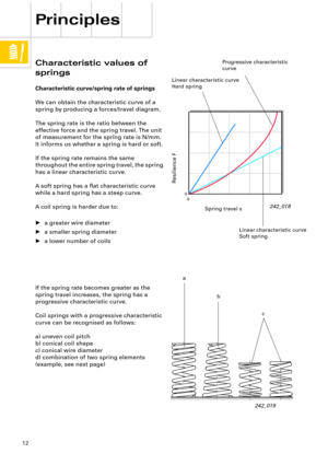
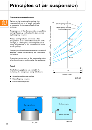
Characteristic values of
springs
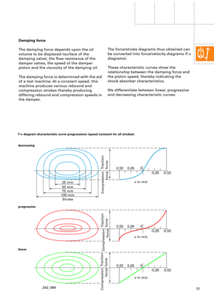
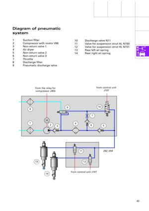
Characteristic curve/spring rate of springs
We can obtain the characteristic curve of a
spring by producing a forces/travel diagram.
The spring rate is the ratio between the
effective force and the spring travel. The unit
of measurement for the spring rate is N/mm.
It informs us whether a spring is hard or soft.
If the spring rate remains the same
throughout the entire spring travel, the spring
has a linear characteristic curve.
A soft spring has a ßat characteristic curve
while a hard spring has a steep curve.
A coil spring is harder due to:
¥ a greater wire diameter
¥ a smaller spring diameter
¥ a lower number of coils
Principles
242_018
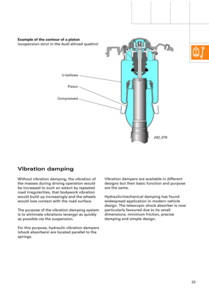
If the spring rate becomes greater as the
spring travel increases, the spring has a
progressive characteristic curve.
Coil springs with a progressive characteristic
curve can be recognised as follows:
a) uneven coil pitch
b) conical coil shape
c) conical wire diameter
d) combination of two spring elements
(example, see next page)
242_019
Spring travel s
Resilience F
Linear characteristic curve
Hard spring
Progressive characteristic
curve
a
b
c Linear characteristic curve
Soft spring
Page 13 of 64
13
-120 -80-400 0 3 6
9 12 15
4080 120
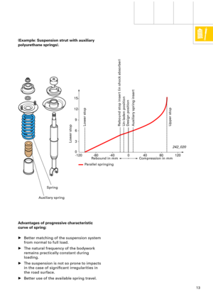
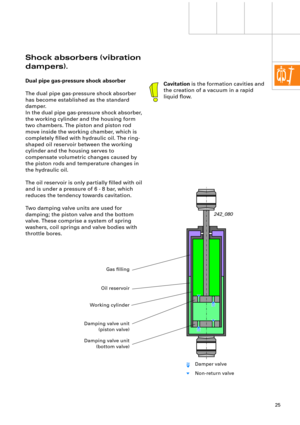
(Example: Suspension strut with auxiliary
polyurethane springs).
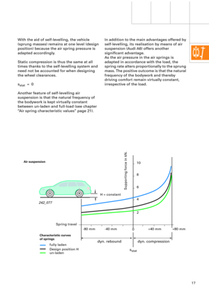
Advantages of progressive characteristic
curve of spring:
¥ Better matching of the suspension system
from normal to full load.
¥ The natural frequency of the bodywork
remains practically constant during
loading.
¥ The suspension is not so prone to impacts
in the case of signiÞcant irregularities in
the road surface.
¥ Better use of the available spring travel.
Rebound in mm Compression in mm
Parallel springing
Lower stop
Upper stop Rebound stop insert (in shock absorber)
Un-laden position
Design position
Auxiliary spring insert Lower stop
242_020
Spring
Auxiliary spring
Page 14 of 64

14
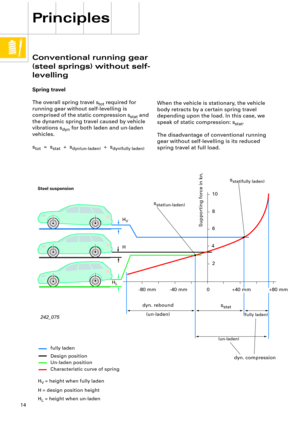
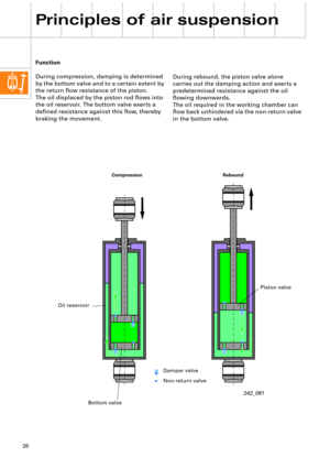
When the vehicle is stationary, the vehicle
body retracts by a certain spring travel
depending upon the load. In this case, we
speak of static compression: s
stat
.
The disadvantage of conventional running
gear without self-levelling is its reduced
spring travel at full load.
Conventional running gear
(steel springs) without self-
levelling
Spring travel
The overall spring travel s
tot
required for
running gear without self-levelling is
comprised of the static compression s
stat
and
the dynamic spring travel caused by vehicle
vibrations s
dyn
for both laden and un-laden
vehicles.
s
tot
= s
stat
+ s
dyn(un-laden)
+ s
dyn(fully laden)
Principles
242_075
Steel suspension
fully laden
Design position
Un-laden position
Supporting force in kn.
H
V
H
H
L
dyn. rebound
s
stat
(un-laden)
dyn. compression
(un-laden)(fully laden)
10
8
6
4
2
+80 mm-40 mm -80 mm
H
V
= height when fully laden
H
= design position height
H
L
= height when un-ladenCharacteristic curve of spring
s
stat(un-laden)
s
stat(fully laden)
+40 mm
0
Page 15 of 64

15
DeÞnitions:
The
un-laden position
...
... is the compression exerted onto the wheels
when the vehicle is ready for the road (fuel
tank completely Þlled, spare wheel and
vehicle tools present).
The
design position
...
... is deÞned as the un-laden position plus the
additional load of three persons, each
weighing 68 kg.
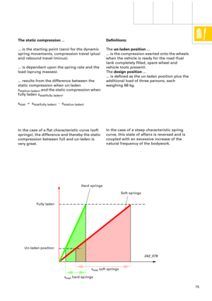
The static compression
...
... is the starting point (zero) for the dynamic
spring movements, compression travel (plus)
and rebound travel (minus).
... is dependant upon the spring rate and the
load (sprung masses).
... results from the difference between the
static compression when un-laden
s
stat(un-laden)
and the static compression when
fully laden s
stat(fully laden)
.
s
stat
= s
stat(fully laden)
- s
stat(un-laden)
In the case of a ßat characteristic curve (soft
springs), the difference and thereby the static
compression between full and un-laden is
very great.
242_076
In the case of a steep characteristic spring
curve, this state of affairs is reversed and is
coupled with an excessive increase of the
natural frequency of the bodywork.
Fully laden
Un-laden position
Hard springs
Soft springs
s
stat
soft springs
s
stat
hard springs
Page 16 of 64
16
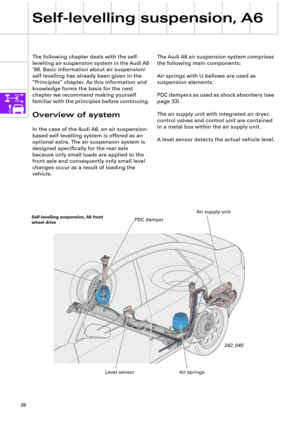
Principles of air suspension
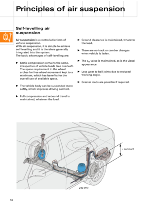
Self-levelling air
suspension
Air suspension is a controllable form of
vehicle suspension.
With air suspension, it is simple to achieve
self-levelling and it is therefore generally
integrated into the system.
The basic advantages of self-levelling are:
¥ Static compression remains the same,
irrespective of vehicle loads (see overleaf).
The space requirement in the wheel
arches for free wheel movement kept to a
minimum, which has beneÞts for the
overall use of available space.
¥ The vehicle body can be suspended more
softly, which improves driving comfort.
¥ Full compression and rebound travel is
maintained, whatever the load.
242_074
¥ Ground clearance is maintained, whatever
the load.
¥ There are no track or camber changes
when vehicle is laden.
¥ The c
w value is maintained, as is the visual
appearance.
¥ Less wear to ball joints due to reduced
working angle.
¥ Greater loads are possible if required.
= constant


.
Advantages of progressive characteristic
curve of spring:
¥ Better matching of the suspe")
