Page 38 of 64

38
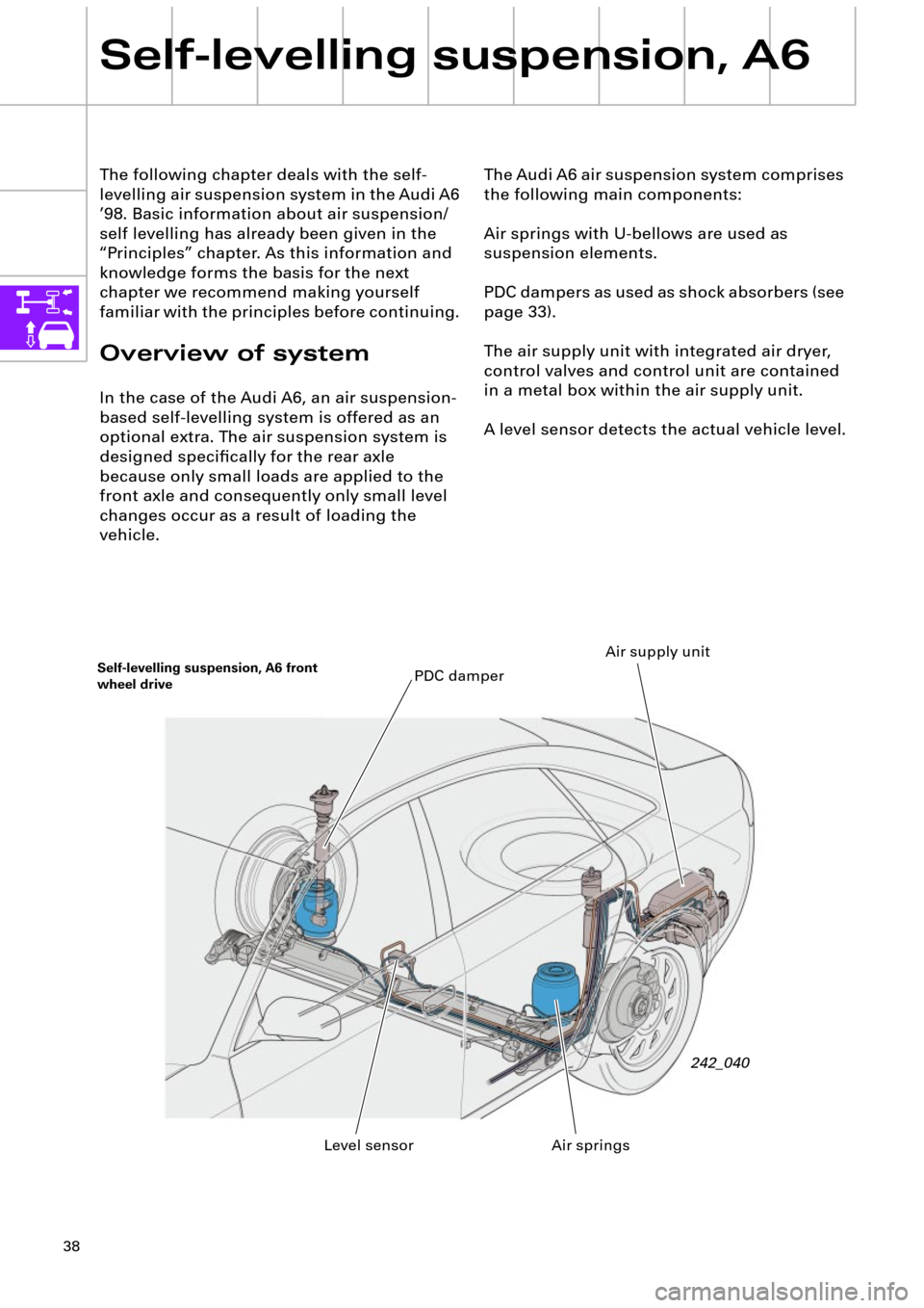
The Audi A6 air suspension system comprises
the following main components:
Air springs with U-bellows are used as
suspension elements.
PDC dampers as used as shock absorbers (see
page 33).
The air supply unit with integrated air dryer,
control valves and control unit are contained
in a metal box within the air supply unit.
A level sensor detects the actual vehicle level. The following chapter deals with the self-
levelling air suspension system in the Audi A6
Õ98. Basic information about air suspension/
self levelling has already been given in the
ÒPrinciplesÓ chapter. As this information and
knowledge forms the basis for the next
chapter we recommend making yourself
familiar with the principles before continuing.
Overview of system
In the case of the Audi A6, an air suspension-
based self-levelling system is offered as an
optional extra. The air suspension system is
designed speciÞcally for the rear axle
because only small loads are applied to the
front axle and consequently only small level
changes occur as a result of loading the
vehicle.
Self-levelling suspension, A6
Self-levelling suspension, A6 front
wheel drive
242_040
Air springs PDC damper
Level sensorAir supply unit
Page 51 of 64

51
Valve for suspension strut
rear left N150 and rear
right N151
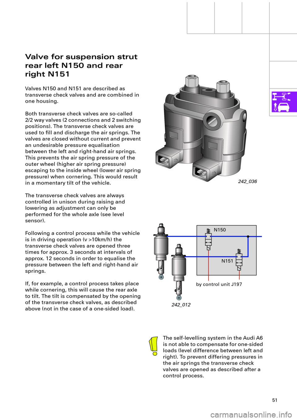
Valves N150 and N151 are described as
transverse check valves and are combined in
one housing.
Both transverse check valves are so-called
2/2 way valves (2 connections and 2 switching
positions). The transverse check valves are
used to Þll and discharge the air springs. The
valves are closed without current and prevent
an undesirable pressure equalisation
between the left and right-hand air springs.
This prevents the air spring pressure of the
outer wheel (higher air spring pressure)
escaping to the inside wheel (lower air spring
pressure) when cornering. This would result
in a momentary tilt of the vehicle.
The transverse check valves are always
controlled in unison during raising and
lowering as adjustment can only be
performed for the whole axle (see level
sensor).
Following a control process while the vehicle
is in driving operation (v >10km/h) the
transverse check valves are opened three
times for approx. 3 seconds at intervals of
approx. 12 seconds in order to equalise the
pressure between the left and right-hand air
springs.
If, for example, a control process takes place
while cornering, this will cause the rear axle
to tilt. The tilt is compensated by the opening
of the transverse check valves, as described
above (not in the case of a one-sided load).
242_036
The self-levelling system in the Audi A6
is not able to compensate for one-sided
loads (level difference between left and
right). To prevent differing pressures in
the air springs the transverse check
valves are opened as described after a
control process.
242_012by control unit J197N150
N151
Page 52 of 64

52
Self-levelling suspension, A6
Self-levelling
suspension sender G84
The vehicle level is detected by the self-
levelling system G84 sender (level
sensor).
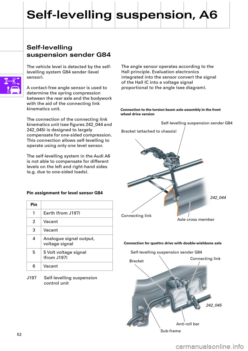
A contact-free angle sensor is used to
determine the spring compression
between the rear axle and the bodywork
with the aid of the connecting link
kinematics unit.
The connection of the connecting link
kinematics unit (see Þgures 242_044 and
242_045) is designed to largely
compensate for one-sided compression.
This connection allows self-levelling to
operate using only one level sensor.
The self-levelling system in the Audi A6
is not able to compensate for different
levels on the left and right-hand sides
(e.g. due to one-sided loads).
Pin assignment for level sensor G84
J197 Self-levelling suspension
control unit Pin
1 Earth (from J197)
2 Vacant
3 Vacant
4 Analogue signal output,
voltage signal
5 5 Volt voltage signal
(from J197)
6 Vacant
242_044 Self-levelling suspension sender G84
Connecting link
Axle cross member
Connection to the torsion beam axle assembly in the front
wheel drive version
Bracket (attached to chassis)
Connecting link Self-levelling suspension sender G84
Bracket
Anti-roll bar
Connection for quattro drive with double-wishbone axle
242_045
Sub-frame
The angle sensor operates according to the
Hall principle. Evaluation electronics
integrated into the sensor convert the signal
of the Hall IC into a voltage signal
proportional to the angle (see diagram).
Page 53 of 64
53
0,5 2,5 4,5
0°
70°
0
Function
A ring magnet is connected to the axle of the
sensor crank (rotor).
A hall IC is positioned eccentrically between a
two-piece iron core (stator). It forms a single
unit together with the evaluation electronics.
Depending on the position of the ring
magnet, the magnetic Þeld which penetrates
the Hall IC changes.
The resulting Hall signal is converted by the
evaluation electronics into a voltage signal
proportional to the angle. The control unit
J197 uses this analogue voltage signal to
determine the current vehicle level.
242_062242_061
242_060
Deßection 35¡ right No deßection
Deßection 35¡ left
Rotor
(ring magnet)
Stator
(divided iron core)
N
SN
S
N
S
Angle VoltsHall IC
Average setting
approximate reference level position
242_063
The angle sensor described here is
also used for the automatic
headlight range control system.
A total of 3 sensors are Þtted into
vehicles with automatic headlight
range control.
Page 54 of 64

54
Self-levelling suspension, A6
Self-diagnosis system G84
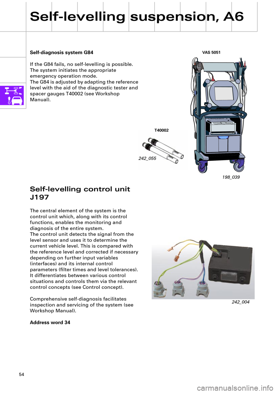
If the G84 fails, no self-levelling is possible.
The system initiates the appropriate
emergency operation mode.
The G84 is adjusted by adapting the reference
level with the aid of the diagnostic tester and
spacer gauges T40002 (see Workshop
Manual).
242_055
T40002
198_039
Self-levelling control unit
J197
The central element of the system is the
control unit which, along with its control
functions, enables the monitoring and
diagnosis of the entire system.
The control unit detects the signal from the
level sensor and uses it to determine the
current vehicle level. This is compared with
the reference level and corrected if necessary
depending on further input variables
(interfaces) and its internal control
parameters (Þlter times and level tolerances).
It differentiates between various control
situations and controls them via the relevant
control concepts (see Control concept).
Comprehensive self-diagnosis facilitates
inspection and servicing of the system (see
Workshop Manual).
Address word 34
242_004
VAS 5051