1998 TOYOTA LAND CRUISER window
[x] Cancel search: windowPage 2199 of 3115
2004 LAND CRUISER (EWD548U)
192Multiplex Communication System
The multiplex communication system communicates among the body ECU, theft deterrent ECU, power window master SW,
power window control SW front RH, power window control SW rear LH, power window control SW rear RH, center airbag
sensor assembly and tilt and telescopic ECU, among the combination meter, engine control module, A/C control assembly
and gateway ECU and controls the following systems according to the signals from respective sensors or switches.
For details, please refer to the new car features and/or the repair manual.
Body ECU
11, 12-Ground : Always approx. 12 volts
22-Ground : Approx. 12 volts with ignition SW at ACC or ON position
10-Ground : Approx. 12 volts with ignition SW at ON or ST position
4, 16-Ground : Always continuity
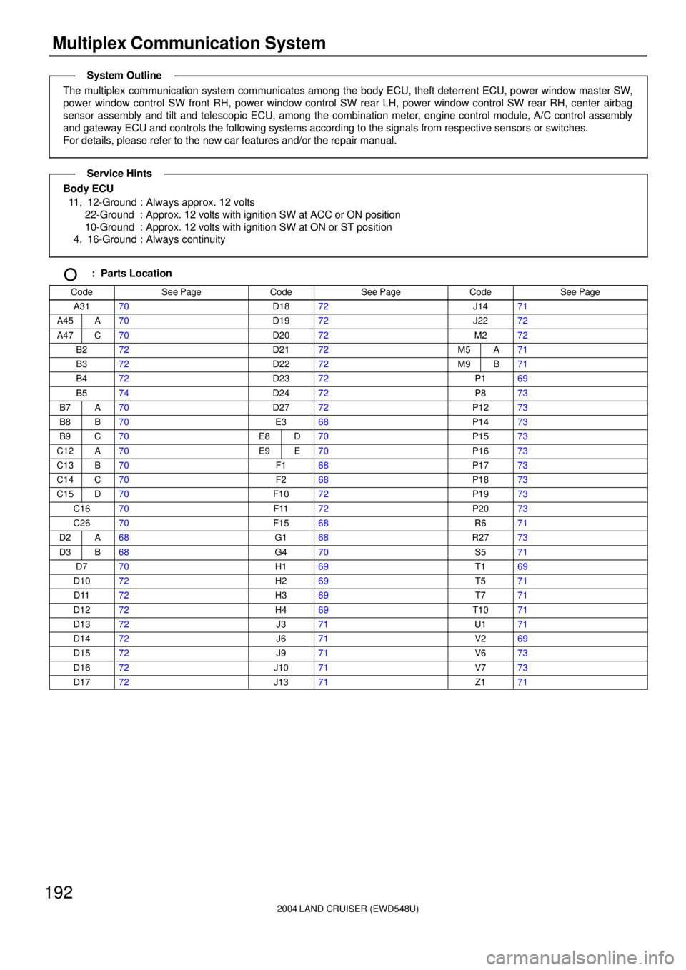
: Parts Location
CodeSee PageCodeSee PageCodeSee Page
A3170D1872J1471
A45A70D1972J2272
A47C70D2072M272
B272D2172M5A71
B372D2272M9B71
B472D2372P169
B574D2472P873
B7A70D2772P1273
B8B70E368P1473
B9C70E8D70P1573
C12A70E9E70P1673
C13B70F168P1773
C14C70F268P1873
C15D70F1072P1973
C1670F1172P2073
C2670F1568R671
D2A68G168R2773
D3B68G470S571
D770H169T169
D1072H269T571
D1172H369T771
D1272H469T1071
D1372J371U171
D1472J671V269
D1572J971V673
D1672J1071V773
D1772J1371Z171
System Outline
Service Hints
Page 2204 of 3115
2004 LAND CRUISER (EWD548U)
197
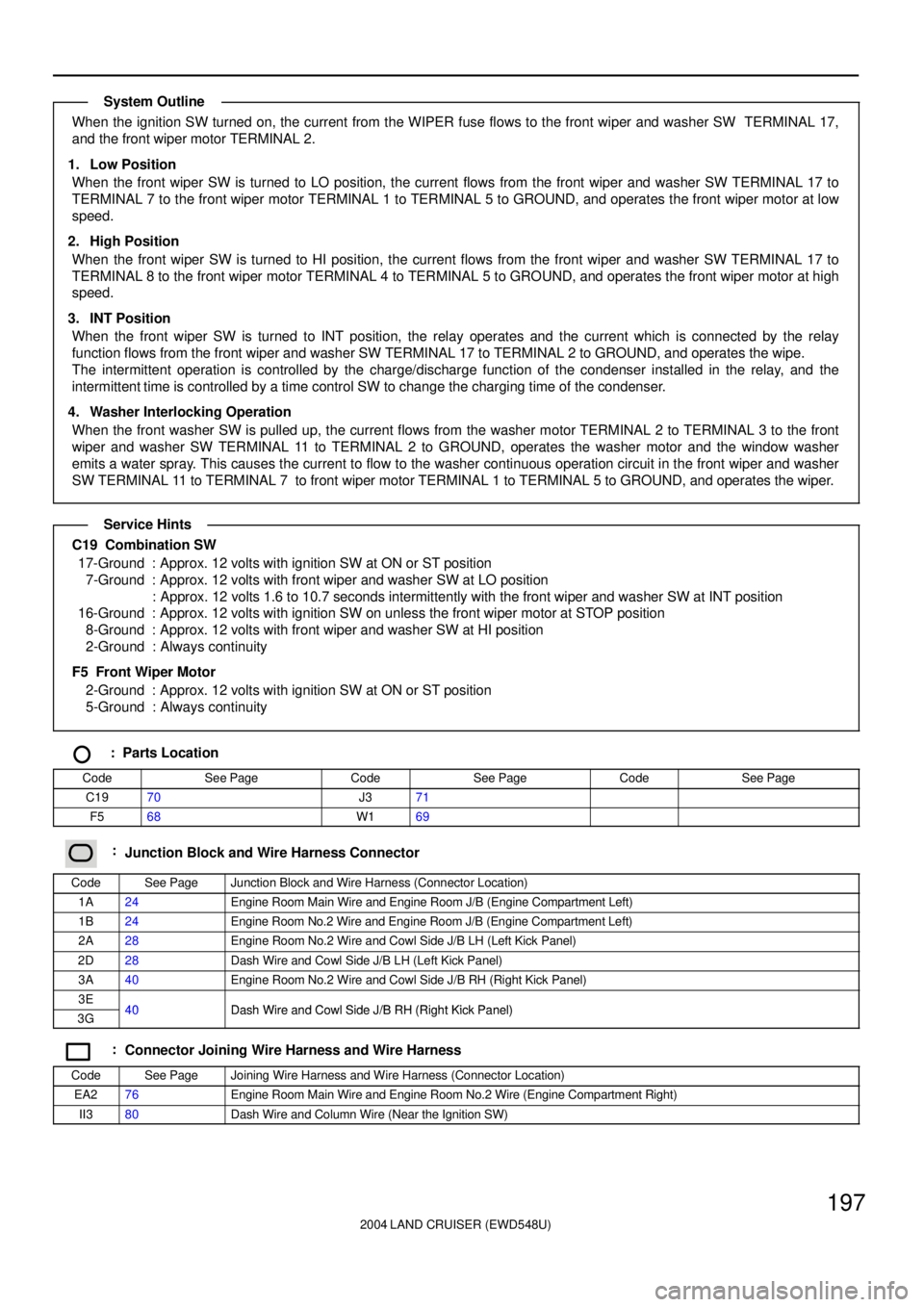
When the ignition SW turned on, the current from the WIPER fuse flows to the front wiper and washer SW TERMINAL 17,
and the front wiper motor TERMINAL 2.
1. Low Position
When the front wiper SW is turned to LO position, the current flows from the front wiper and washer SW TERMINAL 17 to
TERMINAL 7 to the front wiper motor TERMINAL 1 to TERMINAL 5 to GROUND, and operates the front wiper motor at low
speed.
2. High Position
When the front wiper SW is turned to HI position, the current flows from the front wiper and washer SW TERMINAL 17 to
TERMINAL 8 to the front wiper motor TERMINAL 4 to TERMINAL 5 to GROUND, and operates the front wiper motor at high
speed.
3. INT Position
When the front wiper SW is turned to INT position, the relay operates and the current which is connected by the relay
function flows from the front wiper and washer SW TERMINAL 17 to TERMINAL 2 to GROUND, and operates the wipe.
The intermittent operation is controlled by the charge/discharge function of the condenser installed in the relay, and the
intermittent time is controlled by a time control SW to change the charging time of the condenser.
4. Washer Interlocking Operation
When the front washer SW is pulled up, the current flows from the washer motor TERMINAL 2 to TERMINAL 3 to the front
wiper and washer SW TERMINAL 11 to TERMINAL 2 to GROUND, operates the washer motor and the window washer
emits a water spray. This causes the current to flow to the washer continuous operation circuit in the front wiper and washer
SW TERMINAL 11 to TERMINAL 7 to front wiper motor TERMINAL 1 to TERMINAL 5 to GROUND, and operates the wiper.
C19 Combination SW
17-Ground : Approx. 12 volts with ignition SW at ON or ST position
7-Ground : Approx. 12 volts with front wiper and washer SW at LO position
: Approx. 12 volts 1.6 to 10.7 seconds intermittently with the front wiper and washer SW at INT position
16-Ground : Approx. 12 volts with ignition SW on unless the front wiper motor at STOP position
8-Ground : Approx. 12 volts with front wiper and washer SW at HI position
2-Ground : Always continuity
F5 Front Wiper Motor
2-Ground : Approx. 12 volts with ignition SW at ON or ST position
5-Ground : Always continuity
: Parts Location
CodeSee PageCodeSee PageCodeSee Page
C1970J371
F568W169
:Junction Block and Wire Harness Connector
CodeSee PageJunction Block and Wire Harness (Connector Location)
1A24Engine Room Main Wire and Engine Room J/B (Engine Compartment Left)
1B24Engine Room No.2 Wire and Engine Room J/B (Engine Compartment Left)
2A28Engine Room No.2 Wire and Cowl Side J/B LH (Left Kick Panel)
2D28Dash Wire and Cowl Side J/B LH (Left Kick Panel)
3A40Engine Room No.2 Wire and Cowl Side J/B RH (Right Kick Panel)
3E40Dash Wire and Cowl Side J/B RH (Right Kick Panel)3G40Dash Wire and Cowl Side J/B RH (Right Kick Panel)
:Connector Joining Wire Harness and Wire Harness
CodeSee PageJoining Wire Harness and Wire Harness (Connector Location)
EA276Engine Room Main Wire and Engine Room No.2 Wire (Engine Compartment Right)
II380Dash Wire and Column Wire (Near the Ignition SW)
System Outline
Service Hints
Page 2208 of 3115
2004 LAND CRUISER (EWD548U)
201
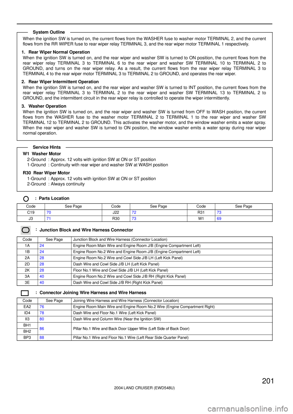
When the ignition SW is turned on, the current flows from the WASHER fuse to washer motor TERMINAL 2, and the current
flows from the RR WIPER fuse to rear wiper relay TERMINAL 3, and the rear wiper motor TERMINAL 1 respectively.
1. Rear Wiper Normal Operation
When the ignition SW is turned on, and the rear wiper and washer SW is turned to ON position, the current flows from the
rear wiper relay TERMINAL 3 to TERMINAL 6 to the rear wiper and washer SW TERMINAL 10 to TERMINAL 2 to
GROUND, and turns on the rear wiper relay. As a result, the current flows from the rear wiper relay TERMINAL 3 to
TERMINAL 4 to the rear wiper motor TERMINAL 3 to TERMINAL 2 to GROUND, and operates the rear wiper.
2. Rear Wiper Intermittent Operation
When the ignition SW is turned on, and the rear wiper and washer SW is turned to INT position, the current flows from the
rear wiper relay TERMINAL 3 to TERMINAL 2 to the rear wiper and washer SW TERMINAL 13 to TERMINAL 2 to
GROUND, and the intermittent circuit in the rear wiper relay is controlled to operate the wiper intermittently.
3. Washer Operation
When the ignition SW is turned on, and the rear wiper and washer SW is turned from OFF to WASH position, the current
flows from the WASHER fuse to the washer motor TERMINAL 2 to TERMINAL 1 to the rear wiper and washer SW
TERMINAL 12 to TERMINAL 2 to GROUND. This activates the washer motor, and the window washer emits a water spray.
When the rear wiper and washer SW is turned to ON position, the window washer emits a water spray during rear wiper
normal operation.
W1 Washer Motor
2-Ground : Approx. 12 volts with ignition SW at ON or ST position
1-Ground : Continuity with rear wiper and washer SW at WASH position
R30 Rear Wiper Motor
1-Ground : Approx. 12 volts with ignition SW at ON or ST position
2-Ground : Always continuity
: Parts Location
CodeSee PageCodeSee PageCodeSee Page
C1970J2272R3173
J371R3073W169
:Junction Block and Wire Harness Connector
CodeSee PageJunction Block and Wire Harness (Connector Location)
1A24Engine Room Main Wire and Engine Room J/B (Engine Compartment Left)
1B24Engine Room No.2 Wire and Engine Room J/B (Engine Compartment Left)
2A28Engine Room No.2 Wire and Cowl Side J/B LH (Left Kick Panel)
2D28Dash Wire and Cowl Side J/B LH (Left Kick Panel)
2K28Floor No.1 Wire and Cowl Side J/B LH (Left Kick Panel)
3A40Engine Room No.2 Wire and Cowl Side J/B RH (Right Kick Panel)
3E40Dash Wire and Cowl Side J/B RH (Right Kick Panel)
:Connector Joining Wire Harness and Wire Harness
CodeSee PageJoining Wire Harness and Wire Harness (Connector Location)
EA276Engine Room Main Wire and Engine Room No.2 Wire (Engine Compartment Right)
ID478Dash Wire and Floor No.1 Wire (Left Kick Panel)
II380Dash Wire and Column Wire (Near the Ignition SW)
BH186Pillar No 1 Wire and Back Door Upper Wire (Left Side of Back Door)BH286Pillar No.1 Wire and Back Door Upper Wire (Left Side of Back Door)
BP388Pillar No.1 Wire and Floor No.1 Wire (Left Rear Side Quarter Panel)
System Outline
Service Hints
Page 2257 of 3115
2004 LAND CRUISER (EWD548U)
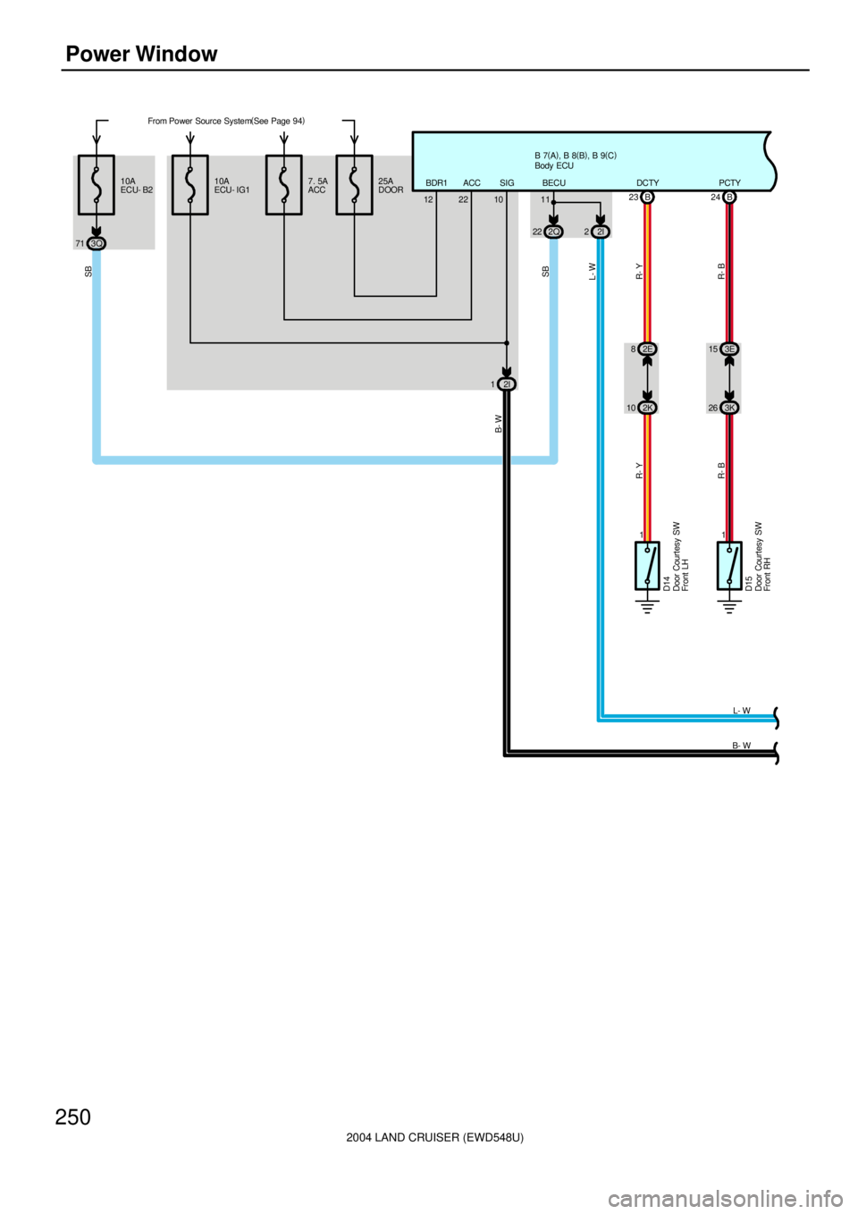
250Power Window
From Power Source System(
See Page 94)
10A
ECU- IG1B 7(
A)
, B 8(
B)
, B 9(
C)
SIG 7. 5A
ACC25A
DOOR
12 22BDR1 ACC 10A
ECU- B2
3Q 712Q 22 2I2 11
11 10 2K82E
26 3K 15 3E B 23 B24
D14
D15R- Y
R- BR- Y
R- B
DCTY PCTY
SB
L- W
10BECU
L- W
SB
Door Courtesy SW
Front LH
Door Courtesy SW
Front RH
Body ECU
2I 1
B- W
B- W
Page 2258 of 3115
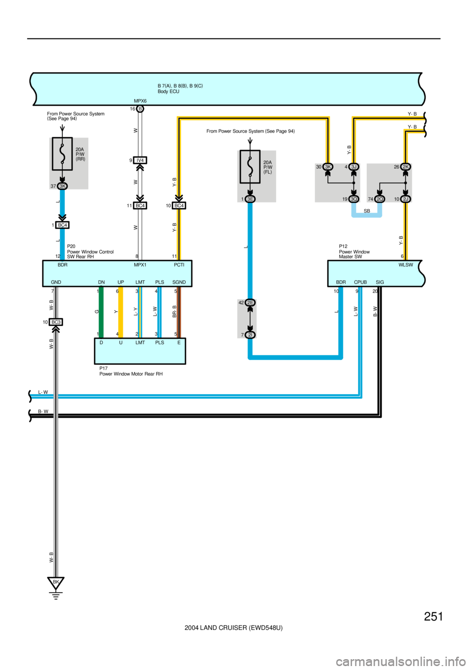
2004 LAND CRUISER (EWD548U)
251
B 7(
A)
, B 8(
B)
, B 9(
C)
26 2K
W
Y- B
2J
16345DN UP LMT PLS SGND
E PLS LMT U D 14235
G
Y
L- Y
L- W
BR- B
10
Y- BWW
P17B 16
IV4 9
BC4 11 BC410 MPX6
3J 4 3K 30
6
Y- B
Y- B
20A
P/W
(
FL)
3E 1
2E 42
2I 7WL SW P12
L
L
B- WL- W
10 209 BDR SIGCPUB 811
PCTI MPX1From Power Source System (
See Page 94)
20A
P/W
(
RR) From Power Source System
(
See Page 94)
3K 37
BC3 10
BK 7 GND
W- B W- B W- B
12P20
BDR3Q 19 2Q74Y- B
Y- B
L- W
L L
SB
Power Window
Master SW
Power Window Motor Rear RH Power Window Control
SW Rear RHBody ECU
B- WBC4 1
Page 2259 of 3115
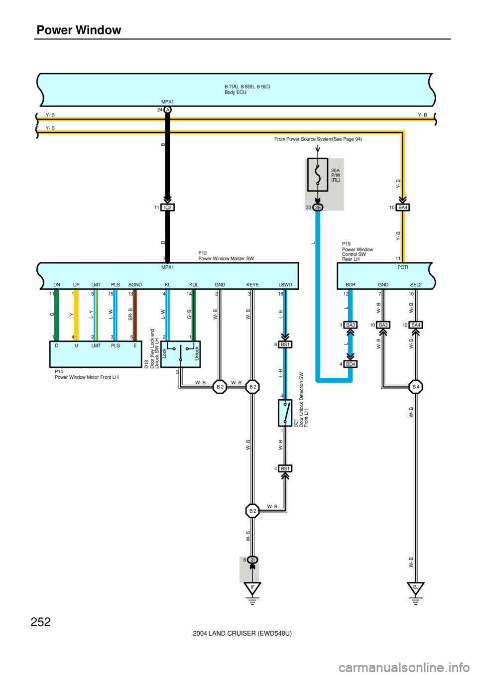
2004 LAND CRUISER (EWD548U)
252Power Window
B 2 B 2 1 2
3
Lock
Unlock
P14
BR- BL- WL- YY G
5 3 2 4 1
DULMTPLSESGND PLS LMT UP DN
13 15 5 1 11
D18
414 2 3 16KLP12 MPX1
BB
MPX17 11 IC2A 24
KUL GND KEYE
L- W
LSWD
G- B
W- B
W- B
L- B
W- B W- B
W- B
BS1 8
1 4
L- B
IF 2I 8BS1 4
B 2
W- B
D21
W- B
W- B
B 7(
A)
, B 8(
B)
, B 9(
C)
Y- B Y- B
BA4 10
BA3 10 BA412
BJ 710 GND SEL2
W- B
W- B W- B
BA3 1
BD4 4 20A
P/W
(
RL) From Power Source System(
See Page 94)
3E 33
L
BDR
12
L L
W- B
W- B W- B
11
PCTI P19
B 4 Y- B
Y- BY- B
Door Key Lock and
Unlock SW LH
Door Unlock Detection SW
Front LH
Power Window Master SW
Power Window Motor Fr ont LHPower Window
Contr ol SW
Rear LH Body ECU
Page 2260 of 3115
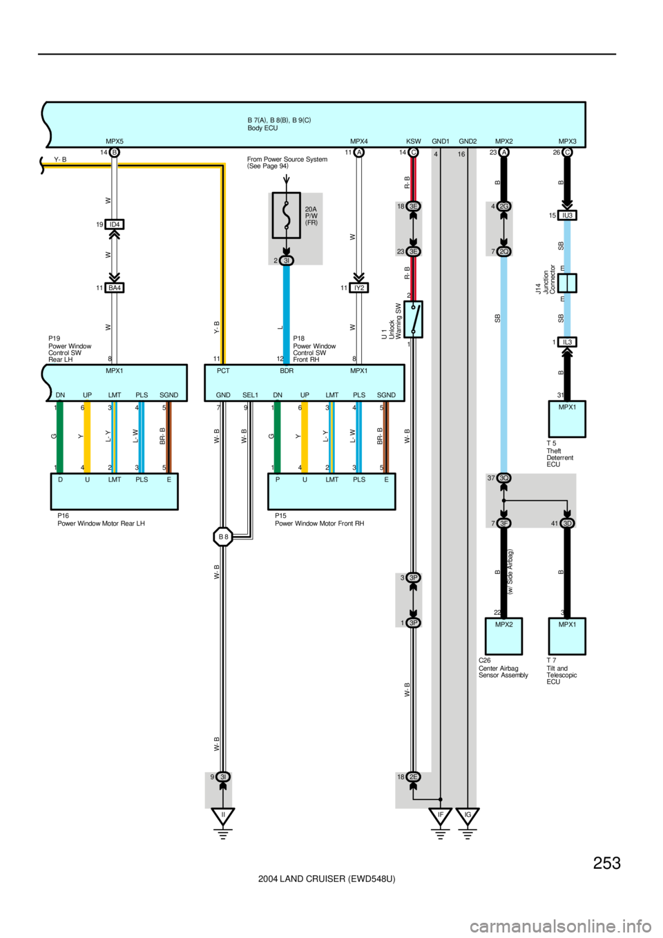
2004 LAND CRUISER (EWD548U)
253
E EIU3 15C 26
SB B
MPX3
J14 (
w/ Side Airbag)
2G 4
2Q 7 23 A
3Q 37
3F 73D41
22
MPX2
C263
MPX1
T 7
B
BSB B
MPX2
IF IG 416 GND1 GND2
T 531
SB B
IL3 1
B 816345DN UP LMT PLS SGND
E PLS LMT U P 14235
G
Y
L- Y
L- W
BR- BWW
P15A 11
IY2 11MPX4
20A
P/W
(
FR)
L
From Power Source System
(
See Page 94)
3I 2
8
MPX1 12
BDR 11
PCT
GND
7
W- B
SEL1
9
W- B
P18
II 3I 9
W- B W- BW
16345DN UP LMT PLS SGND
E PLS LMT U D 14235
G
Y
L- Y
L- W
BR- BWW
P16B 14
ID4 19
BA4 11MPX5
8
MPX1B 7(
A)
, B 8(
B)
, B 9(
C)
P19Y- B
Y- B
MPX1
Center Airbag
Sensor Assembly Power Window Motor Fr ont RH Power Window Motor Rear LHPower Window
Control SW
Front RH Power Window
Contr ol SW
Rear LH
Th eft
Deterr ent
ECU
Tilt and
Te le sco pic
ECU Body ECU
Junction
Connector
KSW
R- B R- B
C 14
23 3E 18 3E
1 2
U 1
Unlock
Warning SW
13P 33P
18 2E
W- BW- B
Page 2261 of 3115
2004 LAND CRUISER (EWD548U)
254Power Window
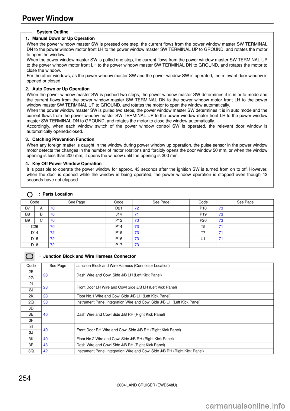
1. Manual Down or Up Operation
When the power window master SW is pressed one step, the current flows from the power window master SW TERMINAL
DN to the power window motor front LH to the power window master SW TERMINAL UP to GROUND, and rotates the motor
to open the window.
When the power window master SW is pulled one step, the current flows from the power window master SW TERMINAL UP
to the power window motor front LH to the power window master SW TERMINAL DN to GROUND, and rotates the motor to
close the window.
For the other windows, as the power window master SW and the power window SW is operated, the relevant door window is
opened or closed.
2. Auto Down or Up Operation
When the power window master SW is pushed two steps, the power window master SW determines it is in auto mode and
the current flows from the power window master SW TERMINAL DN to the power window motor front LH to the power
window master SW TERMINAL UP to GROUND, and rotates the motor to open the window automatically.
When the power window master SW is pulled two steps, the power window master SW determines it is in auto mode and the
current flows from the power window master SW TERMINAL UP to the power window motor front LH to the power window
master SW TERMINAL DN to GROUND, and rotates the motor to close the window automatically.
Accordingly, when each window switch of the power window control SW is operated, the relevant door window is
automatically opened/closed.
3. Catching Prevention Function
When any foreign matter is caught in the window during power window up operation, the pulse sensor in the power window
motor detects the changes in the number of motor rotations and forcibly opens the door window 50 mm, or when the window
opening is less than 200 mm, it opens the window until the opening is 200 mm.
4. Key Off Power Window Operation
It is possible to operate the power window for approx. 43 seconds after the ignition SW is turned from on to off. However,
when the door is opened while the window is being operated, the power window operation is stopped even though 43
seconds have not elapsed.
: Parts Location
CodeSee PageCodeSee PageCodeSee Page
B7A70D2172P1873
B8B70J1471P1973
B9C70P1273P2073
C2670P1473T571
D1472P1573T771
D1572P1673U171
D1872P1773
:Junction Block and Wire Harness Connector
CodeSee PageJunction Block and Wire Harness (Connector Location)
2E28Dash Wire and Cowl Side J/B LH (Left Kick Panel)2G28Dash Wire and Cowl Side J/B LH (Left Kick Panel)
2I28Front Door LH Wire and Cowl Side J/B LH (Left Kick Panel)2J28Front Door LH Wire and Cowl Side J/B LH (Left Kick Panel)
2K28Floor No.1 Wire and Cowl Side J/B LH (Left Kick Panel)
2Q30Instrument Panel Integration Wire and Cowl Side J/B LH (Left Kick Panel)
3D
3E40Dash Wire and Cowl Side J/B RH (Right Kick Panel)
3F
(g )
3I40Front Door RH Wire and Cowl Side J/B RH (Right Kick Panel)3J40Front Door RH Wire and Cowl Side J/B RH (Right Kick Panel)
3K40Floor No.2 Wire and Cowl Side J/B RH (Right Kick Panel)
3P43Dash Wire and Cowl Side J/B RH (Right Kick Panel)
3Q42Instrument Panel Integration Wire and Cowl Side J/B RH (Right Kick Panel)
System Outline