Page 123 of 3115

(b) Without hand-held tester (Using A/T OIL TEMP indicator)
(1) Con")
D14352
Overflow Tube
AT-3-3
- AUTOMATIC TRANSMISSIONAUTOMATIC TRANSMISSION SYSTEM
1857 Author�: Date�:
2004 LAND CRUISER (RM1071U)
(b) Without hand-held tester (Using A/T OIL TEMP indicator)
(1) Connect terminals between CG (4) and TC (13) of
the DLC3 using SST (09843-18040).
(2) Move the shift lever back and forth between N and
D at 1.5 seconds interval for six seconds.
(3) The D shift indicator on the combination meter
comes on for two seconds. This indicates that the
fluid temperature check mode has been started.
(4) The D shift indicator comes on again when the fluid
temperature reaches 46�C (115�F) and blinks
when it exceeds 56�C (130�F).
(5) Allow the engine to idle until the fluid temperature
reaches 46�C (115�F).
6. FLUID LEVEL CHECK
NOTICE:
The fluid temperature must be between 46�C (115�F) and
56�C (130�F) to check the fluid level.
(a) Remove the overflow plug with the engine idling.
(b) Check that the fluid comes out of the overflow tube.
�If fluid does not come out, proceed to step 7.
�If fluid comes out, wait until the overflow slows to a
trickle and proceed to step 8.
7. TRANSMISSION REFILL
(a) Install the overflow plug.
(b) Stop the engine.
(c) Remove the refill plug.
(d) Add 0.4 liters (0.42 US qts, 0.35 lmp. qts) of fluid.
(e) Allow the engine to idle and wait for 10 seconds.
(f) Proceed to step 6.
8. COMPLETE
(a) Install the overflow plug with a new gasket.
(b) Stop the engine.
(c) Install the refill plug with a new gasket.
Torque:
20 NVm (205 kgfVcm, 15 ftVlbf) for overflow plug
39 NVm (400 kgfVcm, 29 ftVlbf) for refill plug
Page 125 of 3115

80 (820, 59)
80 (820, 59)
80 (820, 59)
Front Propeller Shaft
48 (490, 35)
Hole Plug
18 (")
AT080-04
D13664
Air Cleaner Cap
Radiator Reservoir
Fan and Fluid
Coupling Assembly
Fan Shroud
x6x4
80 (820, 59)
80 (820, 59)
80 (820, 59)
80 (820, 59)
Front Propeller Shaft
48 (490, 35)
Hole Plug
18 (185, 13)
Torque Converter
Clutch
50 (510, 37)
74 (750, 54)
50 (510, 37)
N´m (kgf´cm, ft´lbf) : Specified torque
� Non-reusable partTransfer Case Protector
Engine Mouting
Insulator RRx4 x6
37 (377, 27)
71 (724, 52)
�LH Front Exhaust Pipe
�
�
� Transmission
with Transfer
106 (1,080, 78)
106 (1,080, 78)
106 (1,080, 78)
Ground
Cable
Transmission
Shift Control Rod
Pin
Rear Propeller Shaft
�
��
� RH Front Exhaust Pipe
Transfer Shift
Lever Boot
Upper Console Panel Transfer Shift Lever Knob
5.4 (55, 48 in.´lbf)
Clip
Transfer Shift
Lever
Engine No. 1
Under Cover
Crossmember
12 (122, 9)
59 (600, 43)
29 (296, 21)
Engine No. 2
Under Cover �
20 (204, 15)
34 (347, 25)
Oil Cooler Pipe
29 (296, 21)29 (296, 21)
- AUTOMATIC TRANSMISSIONAUTOMATIC TRANSMISSION UNIT
AT-29
1883 Author�: Date�:
2004 LAND CRUISER (RM1071U)
AUTOMATIC TRANSMISSION UNIT
COMPONENTS
Page 126 of 3115
D01624
AT082-06
- AUTOMATIC TRANSMISSIONAUTOMATIC TRANSMISSION UNIT
AT-33
1887 Author�: Date�:
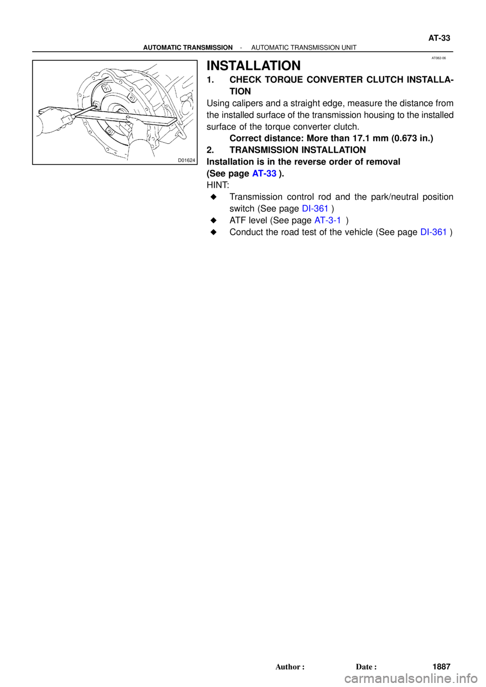
INSTALLATION
1. CHECK TORQUE CONVERTER CLUTCH INSTALLA-
TION
Using calipers and a straight edge, measure the distance from
the installed surface of the transmission housing to the installed
surface of the torque converter clutch.
Correct distance: More than 17.1 mm (0.673 in.)
2. TRANSMISSION INSTALLATION
Installation is in the reverse order of removal
(See page AT-33).
HINT:
�Transmission control rod and the park/neutral position
switch (See page DI-361)
�ATF level (See page AT-3-1)
�Conduct the road test of the vehicle (See page DI-361)
Page 127 of 3115

(b)
(b)
(c)
Lock
D12653
D12654
D12655
AT-30
- AUTOMATIC TRANSMISSIONAUTOMATIC TRANSMISSION UNIT
1884 Author�: Date�:
2004 LAND CRUISER (RM1071U)
REMOVAL
1. REMOVE BATTERY
2. REMO")
AT12V-01
D12652
(a)
(b)
(b)
(c)
Lock
D12653
D12654
D12655
AT-30
- AUTOMATIC TRANSMISSIONAUTOMATIC TRANSMISSION UNIT
1884 Author�: Date�:
2004 LAND CRUISER (RM1071U)
REMOVAL
1. REMOVE BATTERY
2. REMOVE AIR CLEANER CAP DRIVE BELT, FAN AND
FLUID COUPLING ASSEMBLY, FAN SHROUD AND
RADIATOR RESERVOIR
(See page CO-17)
3. DISCONNECT CONNECTORS
(a) Release the lock and disconnect the transmission wire
connector.
(b) Disconnect the 2 transmission wire connectors.
(c) Separate the connector clamp.
4. REMOVE TRANSFER SHIFT LEVER BOOT
(a) Remove the transfer shift lever knob.
(b) Remove upper console panel (See page BO-84).
(c) Remove the 4 bolts and the transfer shift lever boot.
Torque: 5.4 N´m (55 kgf´cm, 48 in.´lbf)
5. REMOVE ENGINE NO. 1 AND NO. 2 UNDER COVERS
6. REMOVE LH AND RH FRONT EXHAUST PIPES
(See page EM-1 15)
7. REMOVE FRONT AND REAR PROPELLER SHAFTS
(See page PR-4)
8. SEPARATE TRANSMISSION SHIFT CONTROL ROD
Remove the clip and pin and separate the shift control rod.
9. SEPARATE TRANSFER SHIFT LEVER
Remove the nut and separate the transfer shift lever rod assem-
bly.
Torque: 12 N´m (122 kgf´cm, 9 ft´lbf)
Page 128 of 3115
(b)
(a)
(a)
(b)(b)
D12657
D12658
D12659
(c)(b)
D12660
- AUTOMATIC TRANSMISSIONAUTOMATIC TRANSMISSION UNIT
AT-31
1885 Author�: Date�:
2004 LAND CRUISER (RM1071U)
10. SEPARATE WIRE HARNESS
(")
D12656
(a)(b)
(a)
(a)
(b)(b)
D12657
D12658
D12659
(c)(b)
D12660
- AUTOMATIC TRANSMISSIONAUTOMATIC TRANSMISSION UNIT
AT-31
1885 Author�: Date�:
2004 LAND CRUISER (RM1071U)
10. SEPARATE WIRE HARNESS
(a) Disconnect 3 connectors.
(b) Remove the 3 clamps from the transmission unit and sep-
arate the transmission wire.
11. REMOVE TORQUE CONVERTER CLUTCH MOUNT-
ING BOLT
(a) Remove the bolt and the hole plug.
Torque: 18 N´m (185 kgf´cm, 13 ft´lbf)
(b) Turn the crankshaft to gain access to each bolt.
(c) Hold the crankshaft pulley nut with a wrench, and remove
the 6 bolts.
Torque: 48 N´m (490 kgf´cm, 35 ft´lbf)
HINT:
At the time of installation, first install the green colored bolt. And
then install the other 5 bolts.
12. DISCONNECT OIL COOLER PIPES
(a) Loosen the 2 union nuts.
(b) Remove the bolt and the clamp.
Torque: 12 N´m (122 kgf´cm, 9 ft´lbf)
(c) Remove the 2 union nuts and disconnect the 2 oil cooler
pipes.
Torque: 34 N´m (347 kgf´cm, 25 ft´lbf)
13. SEPARATE GROUND CABLE
Remove the bolt and separate the ground cable.
Torque: 20 N´m (204 kgf´cm, 15 ft´lbf)
14. REMOVE CROSSMEMBER AND TRANSTER CASE
PROTECTOR
(a) Support the transmission with a jack.
Page 129 of 3115

(b)
(c)
(d)
(a)
(a)
(a)
(c)
(d)(e)
(d)(d)
(e)
(d)
(c)
(c)
(d)
(c)
(e)(e)
(e)
AT-32
- AUTOMATIC TRANSMISSIONAUTOMATIC TRANSMISSION UNIT
1886 Autho")
Q07409
D12661
Inscribing
Mark
D01622
AA
B B
D13665
(a)
(b)
(c)
(d)
(a)
(a)
(a)
(c)
(d)(e)
(d)(d)
(e)
(d)
(c)
(c)
(d)
(c)
(e)(e)
(e)
AT-32
- AUTOMATIC TRANSMISSIONAUTOMATIC TRANSMISSION UNIT
1886 Author�: Date�:
2004 LAND CRUISER (RM1071U)
(b) Remove the 3 bolts and the transter case protector.
Torque: 29 N´m (296 kgf´cm, 21 ft´lbf)
(c) Remove the 8 bolts, the 2 nuts and the crossmember.
Torque:
Bolt: 50 N´m (510 kgf´cm, 37 ft´lbf)
Nut: 74 N´m (750 kgf´cm, 54 ft´lbf)
15. REMOVE ENGINE MOUNTING INSULATOR RR
Remove the 4 bolts and the engine mounting insulator RR.
Torque: 59 N´m (600 kgf´cm, 43 ft´lbf)
HINT:
At the time of installation, install the insulator rear with the in-
scribing mark facing backward.
16. REMOVE TRANSMISSION
(a) Lower the rear end of the transmission unit.
(b) Remove the transmission wire clamp bolt.
(c) Remove the 10 bolts and the transmission unit.
Torque:
Bolt A: 71 N´m (724 kgf´cm, 52 ft´lbf)
Bolt B: 37 N´m (377 kgf´cm, 27 ft´lbf)
17. REMOVE WIRE HARNESS AND HOSE
(a) Remove the 4 bolts.
Torque: 8.0 N´m (82 kgf´cm, 71 in.´lbf)
(b) Release the lock and disconnect the connector.
(c) Disconnect the 5 connectors.
(d) Separate the 6 connector clamps.
(e) Disconnect the 5 hoses and remove the wire harness and
the hose.
Page 130 of 3115
AT07S-04
D12638N´m (kgf´cm, ft´lbf) : Specified torque
Transmission Control Rodx6Shift Lever Assembly Transfer Shift Lever Knob
Upper Console Panel
8.3 (85, 73 in.´lbf)
13 (130, 9)
AT-20
- AUTOMATIC TRANSMISSIONFLOOR SHIFT ASSEMBLY
1874 Author�: Date�:
2004 LAND CRUISER (RM1071U)
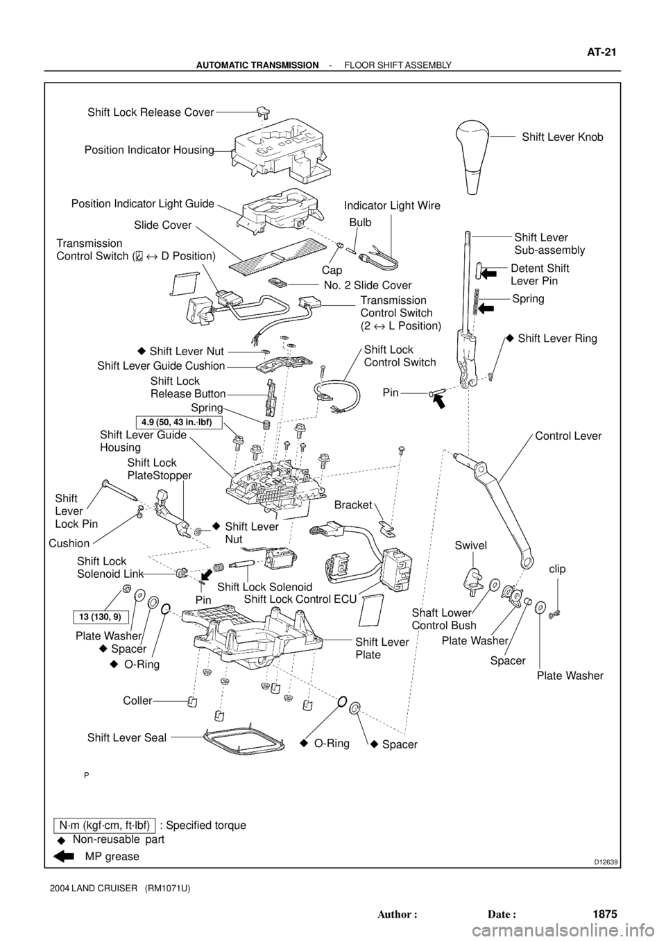
FLOOR SHIFT ASSEMBLY
COMPONENTS
Page 131 of 3115
D12639
Position Indicator Housing
Position Indicator Light Guide
Slide Cover
No. 2 Slide Cover
� Shift Lever Nut
Shift Lever Guide Cushion
Shift Lever Guide
Housing
Bracket
Shift Lock Control ECU
Coller
13 (130, 9)
Plate Washer
� Spacer � O-Ring Shift Lever Seal� O-Ring � SpacerSwivel
Plate Washer
Spacer Shaft Lower
Control Bushclip
Plate Washer Control Lever
�
Pin
� Shift Lever Ring Spring Detent Shift
Lever PinShift Lever
Sub-assembly
Shift Lock Solenoid
Shift Lever
NutPinShift Lever Knob
Transmission
Control Switch (
e D Position)
Shift Lock
Control Switch CapBulb Indicator Light Wire
Shift Lock
Release Button
Spring
N´m (kgf´cm, ft´lbf) : Specified torque
�
MP grease Non-reusable partShift Lever
PlateTransmission
Control Switch
(2 e L Position)
Shift Lock
Solenoid Link
Shift
Lever
Lock Pin
4.9 (50, 43 in.´lbf)
Shift Lock Release Cover
Cushion
Shift Lock
PlateStopper
- AUTOMATIC TRANSMISSIONFLOOR SHIFT ASSEMBLY
AT-21
1875 Author�: Date�:
2004 LAND CRUISER (RM1071U)
 : Specified torque
Transmission Control Rodx6Shift Lever Assembly Transfer Shift Lever Knob
Upper Console Panel
8.3 (85, 73 in.´lbf)
13 (130, 9)
AT-20
- AUTOMAT")