Page 213 of 3115
BE0HJ-1 1
I24912
Meter Cover
Inclination Sensor
Meter Glass
BE-62
- BODY ELECTRICALCOMBINATION METER
2435 Author�: Date�:
2004 LAND CRUISER (RM1071U)
COMPONENTS
Page 217 of 3115
 While driving the vehicle at the speed of 10 km/h, check
the volt")
I24950
Connector C15
161
3
2
1
I25536
BE-66
- BODY ELECTRICALCOMBINATION METER
2439 Author�: Date�:
3. INSPECT SPEEDOMETER VOLTAGE
(a) While driving the vehicle at the speed of 10 km/h, check
the voltage between the terminals 16 and 1 of the com-
bination meter assy.
STANDARD: Fluctuation between 10 to 14 V or less is
repeated 7 times within 1 sec.
4. INSPECT VEHICLE SPEED SENSOR OPERATION
(a) Connect the positive (+) lead from the battery to terminal
1 and negative (-) lead to terminal 2.
(b) Connect the positive (+) lead from the tester to terminal
3 and the negative (-) lead to terminal 2.
(c) Rotate the shaft.
(d) Check that there is voltage change from approx. 0V to 11
V or more between terminals 2 and 3.
HINT:
The voltage change should be performed 4 times for every rev-
olution is not as specified, replace the sensor.
5. INSPECT TACHOMETER / ON-VEHICLE
(a) Connect a tune-up test tachometer, and start the engine.
(b) Compare the tester and tachometer indications.
DC 13.5 V 25 °C at (77°F):
Standard indication (rpm)Allowable range (rpm)
( ): estimated reference values
700630 - 770
1,000900 - 1,100
2,0001,850 - 2,150
3,0002,800 - 3,200
4,0003,800 - 4,200
5,0004,800 - 5,200
6,0005,750 - 6,250
7,0006,700 - 7,300
Page 220 of 3115
I04109
Press
Seat Lower Cushion
Sensing part
I24953
- BODY ELECTRICALCOMBINATION METER
BE-69
2442 Author�: Date�:
Tester connectionConditionSpecified condition
4 - GroundConstantContinuity
If continuity is not as specified, inspect the ground circuit.
17. Passenger seat only:
INSPECT SEAT BELT WARNING OCCUPANT DETEC-
TION SENSOR CONTINUITY
Check that continuity exists between the terminals 1 and 2
when pressing the sensing part of the lower seat cushion.
If operation is not as specified, replace the sensor.
18. INSPECT LIGHT CONTROL RHEOSTAT
(a) Turn the rheostat knob OFF, and check that there is no
continuity between terminal 5 and 4 (Rheostat knob
turned to fully counterclockwise).
(b) Gradually, turn the rheostat knob from the dark side to
bright side, and check that there is continuity between ter-
minal 5 and 4 (Rheostat knob turned to clockwise).
If operation is not as specified, replace the rheostat.
Page 221 of 3115
I25813
1
2
3
4
5
6
7
8
9
1012
13
14
15
16
17
18
19
20 11
I29078
Inclination Sensor
IGN+ E/G EARTH
OUT VccGND
Bottom Surface of Sensor
Connector C15 BE-70
- BODY ELECTRICALCOMBINATION METER
2443 Author�: Date�:
19. INSPECT INCLINATION SENSOR
(a) The inclination sensor is installed in the combination me-
ter. Inspect the inclination sensor by connecting a battery
positive (+) lead to terminal 11 (IGN+) of the meter con-
nector, and a battery negative (-) lead to terminal 1 (E/G
EARTH).
(b) Check if the voltage between terminal Vcc and GND of the
inclination sensor connector is 5 V.
(c) Check the voltage between terminal OUT and GND when
the bottom surface of the inclination sensor is in a level
position. Also check the voltage when it is inclined back-
ward or forward.
Standard Value:
Bottom surface of sensor is set in a level position:
about 4.5 V
Bottom surface of sensor is inclined:
about 0.5 V
Page 223 of 3115
I24744
Seat Belt Warning
Occupant Detection Sensor
Fuel Tank
� Fuel Sender Gauge
Park/ Neutral Position Switch Engine Coolant
Tempareture Sender Gauge
Speed Sensor
Oil Pressure Gauge
- BODY ELECTRICALCOMBINATION METER
BE-57
2430 Author�: Date�:
2004 LAND CRUISER (RM1071U)
Page 253 of 3115

I25040
Built in relayExcept built in relay
I22144
Wire Harness Side:
1
2
3
4
56
I22145
From Back Side:
1 2
3 4
5 6
- BODY ELECTRICALHEADLIGHT AND TAILLIGHT SYSTEM
BE-33
2406 Author�: Date�:
2004 LAND CRUISER (RM1071U)
4. INSPECT ENGINE ROOM R/B RELAY CIRCUIT (See
Pase BE-15)
HINT:
The (Headlight, DIM, Tail relay) is built in engine room junction
block. Also the relay is constructed with a relay block that is in
the junction block as a unit. To disconnect the wire harness con-
necting with relay block is impossible. If the relay has a malfunc-
tion, replace it with junction block assembly wire harness to-
gether.
5. Connector disconnected:
INSPECT AUTOMATIC LIGHT CONTROL SENSOR
CIRCUIT
Disconnect the connector from the sensor and inspect the con-
nector on the wire harness side, as shown in the chart.
HINT:
�Ignition switch is ON.
�Light control switch is in AUTO.
�Vehicle's surroundings are bright.
Tester connectionConditionSpecified condition
6 - GroundConstantContinuity
3 - GroundClose the driver's door again while the ignition
switch OFFNo voltage
3 - GroundIgnition switch position ON5.2 - 9.0V
If circuit is as specified, perform the inspection on the following
page.
If the circuits is not as specified, inspect the circuit connected
to other parts.
6. Connector disconnected:
INSPECT AUTOMATIC LIGHT CONTROL SENSOR
CIRCUIT
Connect the wire harness side connector to the sensor and in-
spect wire harness side connector from the back side, as
shown.
HINT:
�Ignition switch is ON.
�Light control switch is in AUTO.
�Vehicle's surroundings are bright.
Tester connectionConditionSpecified condition
4 - Ground
(CLTS - Body ground)ConstantPulse generation
3 - Ground
(CLTB - Body ground)Ignition switch ON10 - 14V
If the circuits is not as specified, try replacing the sensor with a
new one.
Page 254 of 3115
BE0H8-1 1
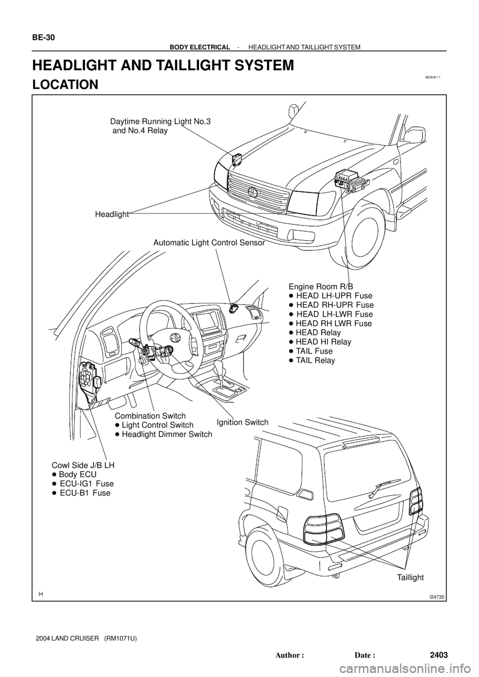
I24735
Cowl Side J/B LH
� Body ECU
� ECU-IG1 Fuse
� ECU-B1 Fuse
Combination Switch
� Light Control Switch
� Headlight Dimmer SwitchIgnition Switch Headlight
Engine Room R/B
� HEAD LH-UPR Fuse
� HEAD RH-UPR Fuse
� HEAD LH-LWR Fuse
� HEAD RH LWR Fuse
� HEAD Relay
� HEAD HI Relay
� TAIL Fuse
� TAIL Relay Automatic Light Control Sensor
Taillight Daytime Running Light No.3
and No.4 Relay
BE-30
- BODY ELECTRICALHEADLIGHT AND TAILLIGHT SYSTEM
2403 Author�: Date�:
2004 LAND CRUISER (RM1071U)
HEADLIGHT AND TAILLIGHT SYSTEM
LOCATION
Page 321 of 3115

(d) Continue to apply volta")
I21323
41
I06191
1 2
4 5
I06192
1 2
4 5
I06189
1
4 3
5
I06190
1
4 3
5
- BODY ELECTRICALPOWER WINDOW CONTROL SYSTEM
BE-81
2454 Author�: Date�:
2004 LAND CRUISER (RM1071U)
(d) Continue to apply voltage and check that the current
changes to less than 1 A within 4 to 90 seconds.
(e) Disconnect the leads from the terminals.
(f) Approximately 60 seconds later, connect the positive (+)
lead from the battery to terminal 1 and the negative (-)
lead to terminal 4, and check that the window begins to
descend.
If operation is not as specified, replace the motor.
6. INSPECT JAM PROTECTION LIMIT SWITCH OPERA-
TION
(a) Connect the positive (+) lead from the ohmmeter to termi-
nal 2 and the negative (-) lead to terminal 5.
(b) Connect the positive (+) lead from the battery to terminal
1 and the negative (-) lead to terminal 4.
(c) Check that the continuity exists when the window goes
up.
(d) Check that the no continuity exists when the window is in
the fully closed position.
If operation is not as specified, replace the motor.
NOTICE:
If connecting the wire harness wrongly, the sensor might
be damaged so caution is necessary.
7. INSPECT JAM PROTECTION PULSE SWITCH OP-
ERATION
(a) Connect the positive (+) lead from the TOYOTA electrical
tester to terminal 3 and the negative (-) lead to terminal
5.
(b) Connect the positive (+) lead from the battery to terminal
1 and the negative (-) lead to terminal 4.
(c) Check that pulse is generated during the motor running.
(d) Reverse the polarity and check that pulse is generated.
If operation is not as specified, replace the motor.
NOTICE:
If connecting the wire harness wrongly, the sensor might
be damaged so caution is necessary.