Page 103 of 3115
I08487
Power Transistor
Air Inlet Temperature
Sensor
Cover
Fan
Heater Case
Blower Motor Heater Case Heater Radiator � O-Ring
Heater Radiator Pipe
Air Mix Servomotor
� Non - reusable part
AC-46
- AIR CONDITIONINGREAR HEATER UNIT
2771 Author�: Date�:
2004 LAND CRUISER (RM1071U)
Page 104 of 3115
AC1KP-03
I06819
I06821
I06681
I06818
I07896
- AIR CONDITIONINGREAR HEATER UNIT
AC-49
2774 Author�: Date�:
2004 LAND CRUISER (RM1071U)
DISASSEMBLY
1. REMOVE AIR MIX SERVOMOTOR
Remove the 3 screws and the air mix servomotor.
2. REMOVE HEATER RADIATOR
(a) Remove the 3 screws and 2 clamps
(b) Pull out the heater radiator.
(c) Remove the 2 screws, 2 clamps and the heater radiator
pipes.
(d) Remove the 2 O-rings.
HINT:
At the time of reassembly, do not reuse the O-rings
3. REMOVE POWER TRANSISTOR
Remove the 2 screws and the power transistor.
4. REMOVE BLOWER MOTOR
(a) Remove the 3 screws and the cover.
(b) Remove the 4 screws, the 3 holding springs and separate
the heater cases.
Page 106 of 3115
AC1KQ-05
I07898
1
2
- AIR CONDITIONINGREAR HEATER UNIT
AC-51
2776 Author�: Date�:
2004 LAND CRUISER (RM1071U)
INSPECTION
1. INSPECT HEATER RADIATOR
If the fins are clogged, clean them with compressed air.
2. INSPECT BLOWER MOTOR OPERATION
Connect battery positive (+) lead to terminal 1 and battery neg-
ative (-) lead to terminal 2, then check that the motor rotates
smoothly.
If operation is not as specified, replace the blower motor.
3. INSPECT AIR MIX SERVOMOTOR (See page DI-1354)
4. INSPECT AIR MIX DAMPER POSITION SENSOR
(See page DI-1345)
Page 109 of 3115
AC1KO-04
I03973
I05080
Second Ridge
Hose Clip
Water Hose
I03924
- AIR CONDITIONINGREAR HEATER UNIT
AC-47
2772 Author�: Date�:
2004 LAND CRUISER (RM1071U)
REMOVAL
1. DRAIN ENGINE COOLANT FROM RADIATOR
HINT:
It is not necessary to drain out all the coolant.
2. DISCONNECT WATER HOSES FROM HEATER RA-
DIATOR PIPES
(a) Using pliers, grip the claws of the clip and slide the clip
along the hose
(b) Disconnect the water hoses
HINT:
At the time of installation, push the water hose on to the heater
radiator pipe to the second ridge on the pipe.
3. REMOVE FRONT SEATS
4. REMOVE REAR CONSOLE BOX
5. REMOVE FRONT CONSOLE BOX COVER
6. REMOVE LOWER CENTER CLUSTER FINISH PANEL
7. REMOVE FRONT DOOR SCUFF PLATE
8. REMOVE COWL SIDE TRIMS
9. REMOVE REAR DOOR SCUFF PLATES
10. REMOVE CENTER PILLAR GARNISHES
11. SLIDE FLOOR CARPET BACKWARD
12. REMOVE COOLER BRACKET
Remove the 4 bolts and the cooler bracket.
Page 114 of 3115
AT07I-05
D13117N´m (kgf´cm, ft´lbf) : Specified torqueClip
Oil Cooler PipeClip
Clip
Clip
Clip
Oil Cooler Stay
Oil Cooler
12 (122, 9)
Oil Cooler Bracket
Radiator Grille Sub-assy
7.5 (76, 66 in.´lbf)
7.5 (76, 66 in.´lbf)
Power Steering
Oil Cooler Sub-assy
Oil Cooler Bracket
5.0 (51, 44 in.´lbf)
5.0 (51, 44 in.´lbf)5.0 (51, 44 in.´lbf)
5.0 (51, 44 in.´lbf)
5.0 (51, 44 in.´lbf)
12 (122, 9)
12 (122, 9)
AT-16
- AUTOMATIC TRANSMISSIONAIR COOLED OIL COOLER
1870 Author�: Date�:
2004 LAND CRUISER (RM1071U)
AIR COOLED OIL COOLER
COMPONENTS
Page 116 of 3115
AT113-01
D12665
D01688
D01689
D01690
- AUTOMATIC TRANSMISSIONAIR COOLED OIL COOLER
AT-17
1871 Author�: Date�:
2004 LAND CRUISER (RM1071U)
REMOVAL
1. REMOVE RADIATOR GRILLE SUB-ASSY
(a) Remove the 3 screws.
(b) Release the 2 clips and remove the radiator grille sub-
assy.
2. SEPARATE POWER STEERING OIL COOLER SUB-
ASSY
Remove the 2 bolts and separate the power steering oil cooler
sub-assy .
Torque: 7.5 N´m (76 kgf´cm, 66 in.´lbf)
3. REMOVE OIL COOLER
(a) Loosen the 2 clips and disconnect the 2 hoses.
(b) Remove the 4 bolts and oil cooler.
Torque: 12 N´m (117 kgf´cm, 8 ft´lbf)
(c) Remove the 8 bolts, the 2 oil cooler brackets and the 2
stays.
Torque: 4.9 N´m (50 kgf´cm, 43 in.´lbf)
Page 125 of 3115

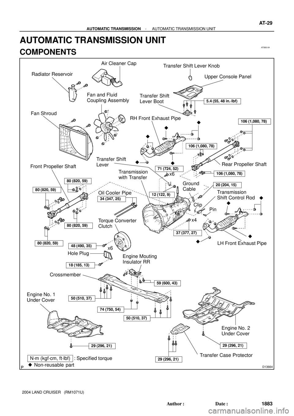
AT080-04
D13664
Air Cleaner Cap
Radiator Reservoir
Fan and Fluid
Coupling Assembly
Fan Shroud
x6x4
80 (820, 59)
80 (820, 59)
80 (820, 59)
80 (820, 59)
Front Propeller Shaft
48 (490, 35)
Hole Plug
18 (185, 13)
Torque Converter
Clutch
50 (510, 37)
74 (750, 54)
50 (510, 37)
N´m (kgf´cm, ft´lbf) : Specified torque
� Non-reusable partTransfer Case Protector
Engine Mouting
Insulator RRx4 x6
37 (377, 27)
71 (724, 52)
�LH Front Exhaust Pipe
�
�
� Transmission
with Transfer
106 (1,080, 78)
106 (1,080, 78)
106 (1,080, 78)
Ground
Cable
Transmission
Shift Control Rod
Pin
Rear Propeller Shaft
�
��
� RH Front Exhaust Pipe
Transfer Shift
Lever Boot
Upper Console Panel Transfer Shift Lever Knob
5.4 (55, 48 in.´lbf)
Clip
Transfer Shift
Lever
Engine No. 1
Under Cover
Crossmember
12 (122, 9)
59 (600, 43)
29 (296, 21)
Engine No. 2
Under Cover �
20 (204, 15)
34 (347, 25)
Oil Cooler Pipe
29 (296, 21)29 (296, 21)
- AUTOMATIC TRANSMISSIONAUTOMATIC TRANSMISSION UNIT
AT-29
1883 Author�: Date�:
2004 LAND CRUISER (RM1071U)
AUTOMATIC TRANSMISSION UNIT
COMPONENTS
Page 127 of 3115

AT12V-01
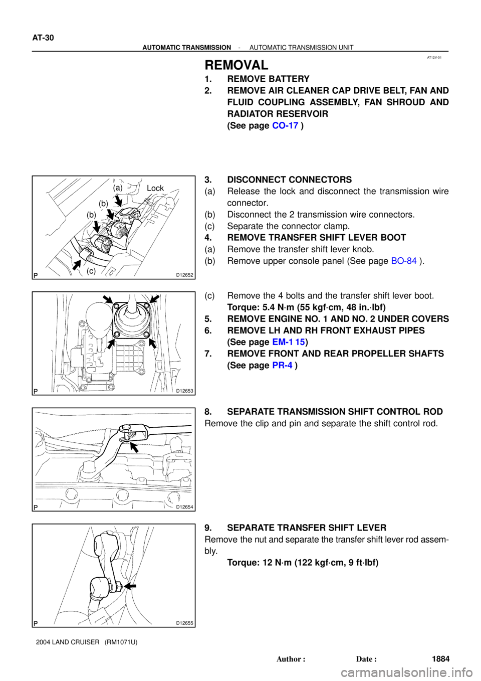
D12652
(a)
(b)
(b)
(c)
Lock
D12653
D12654
D12655
AT-30
- AUTOMATIC TRANSMISSIONAUTOMATIC TRANSMISSION UNIT
1884 Author�: Date�:
2004 LAND CRUISER (RM1071U)
REMOVAL
1. REMOVE BATTERY
2. REMOVE AIR CLEANER CAP DRIVE BELT, FAN AND
FLUID COUPLING ASSEMBLY, FAN SHROUD AND
RADIATOR RESERVOIR
(See page CO-17)
3. DISCONNECT CONNECTORS
(a) Release the lock and disconnect the transmission wire
connector.
(b) Disconnect the 2 transmission wire connectors.
(c) Separate the connector clamp.
4. REMOVE TRANSFER SHIFT LEVER BOOT
(a) Remove the transfer shift lever knob.
(b) Remove upper console panel (See page BO-84).
(c) Remove the 4 bolts and the transfer shift lever boot.
Torque: 5.4 N´m (55 kgf´cm, 48 in.´lbf)
5. REMOVE ENGINE NO. 1 AND NO. 2 UNDER COVERS
6. REMOVE LH AND RH FRONT EXHAUST PIPES
(See page EM-1 15)
7. REMOVE FRONT AND REAR PROPELLER SHAFTS
(See page PR-4)
8. SEPARATE TRANSMISSION SHIFT CONTROL ROD
Remove the clip and pin and separate the shift control rod.
9. SEPARATE TRANSFER SHIFT LEVER
Remove the nut and separate the transfer shift lever rod assem-
bly.
Torque: 12 N´m (122 kgf´cm, 9 ft´lbf)