Page 315 of 3115

I07251
21
I07252
21
I07256
(a)
(b)
21
1 2
N21868
21
N21869
21 BE-1 14
- BODY ELECTRICALPOWER SEAT CONTROL SYSTEM
2487 Author�: Date�:
2004 LAND CRUISER (RM1071U)
12. INSPECT LIFTER MOTOR PTC THERMISTOR OPERA-
TION
(a) Connect the positive (+) lead from the battery to terminal
1 (2), the positive (+) lead from the ammeter to terminal
2 (1) and the negative (-) lead to the battery negative (-)
terminal, then move the seat cushion to the highest posi-
tion.
(b) Continue to apply voltage, check that the current changes
to less than 1 ampere within 4 to 90 seconds.
(c) Disconnect the leads from the terminals.
(d) Approximately 60 seconds later, connect the positive (+)
lead from the battery to terminal 2 (1) and the negative (-)
lead to terminal 1 (2), check that the seat cushion begins
to descend.
If operation is not as specified, replace the seat adjuster.
13. INSPECT RECLINING MOTOR OPERATION
(a) Connect the positive (+) lead from the battery to terminal
1 and the negative (-) lead to terminal 2, check that the
motor turns clockwise.
(b) Reverse the polarity, check that the motor turns counter-
clockwise.
If operation is not as specified, replace the seat adjuster.
14. INSPECT RECLINING MOTOR PTC THERMISTOR OP-
ERATION
(a) Connect the positive (+) lead from the battery to terminal
2, the positive (+) lead from the ammeter to terminal 1 and
the negative (-) lead to the battery negative (-) terminal,
then recline the seat back to the most forward position.
(b) Continue to apply voltage, check that the current changes
to less than 1 ampere within 4 to 90 seconds.
(c) Disconnect the leads from the terminals.
(d) Approximately 60 seconds later, connect the positive (+)
lead from the battery to terminal 1 and the negative (-)
lead to terminal 2, check that the seat back begins to fall
backward.
If operation is not as specified, replace the seat adjuster.
Page 320 of 3115

I075004 1
I075014 1
I06178
1
4
I06177
1
4
I21322
4 1
BE-80
- BODY ELECTRICALPOWER WINDOW CONTROL SYSTEM
2453 Author�: Date�:
2004 LAND CRUISER (RM1071U)
3. Driver 's door and rear right door:
INSPECT POWER WINDOW MOTOR OPERATION
(a) Connect the positive (+) lead from the battery to terminal
1 and the negative (-) lead to terminal 4, check that the
motor turns counterclockwise.
(b) Reverse the polarity, check that the motor turns clock-
wise.
If operation is not as specified, replace the motor.
4. Passenger 's door and rear left door:
INSPECT POWER WINDOW MOTOR OPERATION
(a) Connect the positive (+) lead from the battery to terminal
4 and the negative (-) lead to terminal 1, check that the
motor turns clockwise.
(b) Reverse the polarity, check that the motor turns counter-
clockwise.
If operation is not as specified, replace the motor.
5. INSPECT POWER WINDOW MOTOR PTC THERM-
ISTOR OPERATION
(a) Disconnect the connector from the power window motor.
(b) Connect the positive (+) lead from the ammeter to termi-
nal 1 on the wire harness side connector and the negative
(-) lead to negative terminal of the battery.
(c) Connect the positive (+) lead from the battery to terminal
4 on the wire harness side connector, and raise the win-
dow to the fully position.
Page 343 of 3115

BE-10
- BODY ELECTRICALTROUBLESHOOTING
2383 Author�: Date�:
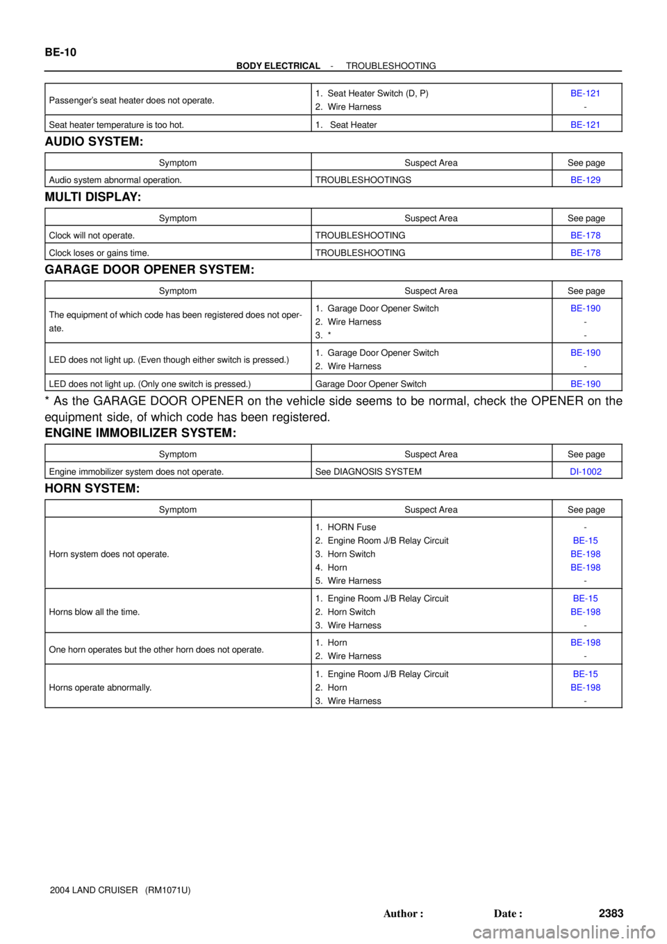
2004 LAND CRUISER (RM1071U) Passenger's seat heater does not operate.
1. Seat Heater Switch (D, P)
2. Wire HarnessBE-121
-
Seat heater temperature is too hot.1. Seat HeaterBE-121
AUDIO SYSTEM:
SymptomSuspect AreaSee page
Audio system abnormal operation.TROUBLESHOOTINGSBE-129
MULTI DISPLAY:
SymptomSuspect AreaSee page
Clock will not operate.TROUBLESHOOTINGBE-178
Clock loses or gains time.TROUBLESHOOTINGBE-178
GARAGE DOOR OPENER SYSTEM:
SymptomSuspect AreaSee page
The equipment of which code has been registered does not oper-
ate.1. Garage Door Opener Switch
2. Wire Harness
3. *BE-190
-
-
LED does not light up. (Even though either switch is pressed.)1. Garage Door Opener Switch
2. Wire HarnessBE-190
-
LED does not light up. (Only one switch is pressed.)Garage Door Opener SwitchBE-190
* As the GARAGE DOOR OPENER on the vehicle side seems to be normal, check the OPENER on the
equipment side, of which code has been registered.
ENGINE IMMOBILIZER SYSTEM:
SymptomSuspect AreaSee page
Engine immobilizer system does not operate.See DIAGNOSIS SYSTEMDI-1002
HORN SYSTEM:
SymptomSuspect AreaSee page
Horn system does not operate.
1. HORN Fuse
2. Engine Room J/B Relay Circuit
3. Horn Switch
4. Horn
5. Wire Harness-
BE-15
BE-198
BE-198
-
Horns blow all the time.
1. Engine Room J/B Relay Circuit
2. Horn Switch
3. Wire HarnessBE-15
BE-198
-
One horn operates but the other horn does not operate.1. Horn
2. Wire HarnessBE-198
-
Horns operate abnormally.
1. Engine Room J/B Relay Circuit
2. Horn
3. Wire HarnessBE-15
BE-198
-
Page 599 of 3115

Z00030
B00807
B00808
B
A
AC2024
CORRECT WRONG
- CHARGINGCHARGING SYSTEM
CH-3
1838 Author�: Date�:
2004 LAND CRUISER (RM1071U)
5. INSPECT DRIVE BELT
HINT:
A belt tensioner is used, so checking the belt tension is not nec-
essary.
(a) Visually check the drive belt for excessive wear, frayed
cords etc.
If necessary, replace the drive belt.
HINT:
�Cracks on the rib side of a drive belt are considered ac-
ceptable. If the drive belt has chunks missing from the
ribs, it should be replaced.
�The drive belt tension can be released by turning the belt
tensioner counterclockwise. The pulley bolt for the belt
tensioner has a left-hand thread.
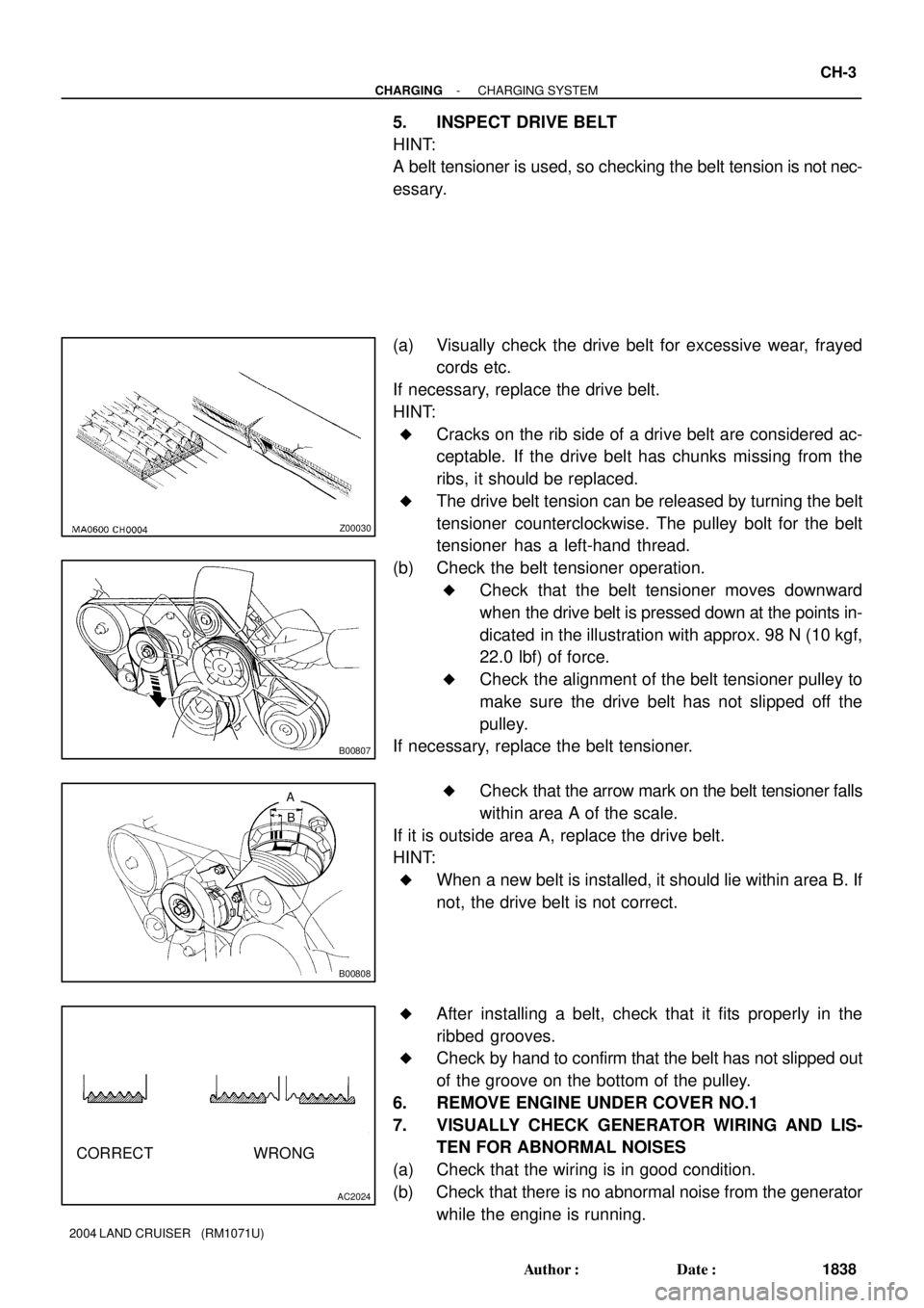
(b) Check the belt tensioner operation.
�Check that the belt tensioner moves downward
when the drive belt is pressed down at the points in-
dicated in the illustration with approx. 98 N (10 kgf,
22.0 lbf) of force.
�Check the alignment of the belt tensioner pulley to
make sure the drive belt has not slipped off the
pulley.
If necessary, replace the belt tensioner.
�Check that the arrow mark on the belt tensioner falls
within area A of the scale.
If it is outside area A, replace the drive belt.
HINT:
�When a new belt is installed, it should lie within area B. If
not, the drive belt is not correct.
�After installing a belt, check that it fits properly in the
ribbed grooves.
�Check by hand to confirm that the belt has not slipped out
of the groove on the bottom of the pulley.
6. REMOVE ENGINE UNDER COVER NO.1
7. VISUALLY CHECK GENERATOR WIRING AND LIS-
TEN FOR ABNORMAL NOISES
(a) Check that the wiring is in good condition.
(b) Check that there is no abnormal noise from the generator
while the engine is running.
Page 604 of 3115
CH06J-03
B16654
B16655
B16362
B16369SST (B)
SST (A)
Turn
B16371
SST (C)
SST (B)
Insert
CH-8
- CHARGINGGENERATOR
1843 Author�: Date�:
2004 LAND CRUISER (RM1071U)
DISASSEMBLY
1. REMOVE REAR END COVER
(a) Remove the 3 screws and rear end cover.
2. REMOVE END COVER
(a) Remove the 3 nuts and end cover.
(b) Remove the terminal insulator.
3. REMOVE BRUSH HOLDER
(a) Remove the rear seal plate from the brush holder.
(b) Remove the 2 screws and brush holder.
(c) Remove the front seal plate from the coil assembly.
4. REMOVE PULLEY
(a) Hold SST (A) with a torque wrench, and tighten SST (B)
clockwise to the specified torque.
SST 09820-6301 1
Torque: 39 N´m (400 kgf´cm, 29 ft´lbf)
(b) Check that SST (A) is secured to the rotor shaft.
(c) Mount SST (C) in a vise.
(d) Insert SST (B) into SST (C), and attach the pulley nut to
SST (C).
Page 607 of 3115
CH06N-05
B16653
B00809
CH-16
- CHARGINGGENERATOR
1851 Author�: Date�:
2004 LAND CRUISER (RM1071U)
INSTALLATION
1. INSTALL GENERATOR
(a) Install the generator with the bolt and 2 nuts.
Torque:
Bolt: 39 N´m (400 kgf´cm, 29 ft´lbf)
Nut 10 mm: 39 N´m (400 kgf´cm, 29 ft´lbf)
Nut 8 mm: 15.5 N´m (158 kgf´cm, 11 ft´lbf)
(b) Connect the generator connector.
(c) Connect the generator wire with the nut.
Torque: 9.8 N´m (100 kgf´cm, 87 in.´lbf)
(d) Install the terminal cap.
(e) Install the wire clamp to the cord clip on the generator.
2. INSTALL PS VANE PUMP PULLEY
(See page SR-47)
3. INSTALL RADIATOR ASSEMBLY
(See page CO-19)
4. INSTALL GENERATOR DRIVE BELT
Install the belt by turning the belt tensioner counterclockwise.
HINT:
The pulley bolt for the belt tensioner has a left - hand thread.
5. FULL ENGINE COOLANT
6. START ENGINE AND CHECK FOR LEAKS
7. RECHECK ENGINE COOLANT LEVEL
8. PERFORM ON-VEHICLE INSPECTION
(See page CH-2)
9. INSTALL ENGINE UNDER COVER NO.1
Page 608 of 3115
CH0M6-01
B16368
Pulley
B12276
SST
B16656
B16369
TurnSST (A)
SST (B)
B16371
SST (C)
SST (A)
Insert
- CHARGINGGENERATOR
CH-13
1848 Author�: Date�:
2004 LAND CRUISER (RM1071U)
REASSEMBLY
1. INSTALL ROTOR TO DRIVE END FRAME
(a) Place the drive end frame on the pulley.
(b) Install the rotor to the drive end frame.
2. INSTALL COIL ASSEMBLY
(a) Place the generator washer on the rotor.
(b) Using SST and a press, slowly press in the coil assembly.
SST 09285-76010
(c) Install the coil assembly with the 4 bolts.
Torque: 5.8 N´m (59 kgf´cm, 51 in.´lbf)
3. INSTALL PULLEY
(a) Install the pulley to the rotor shaft by tightening the pulley
nut by hand.
(b) Hold SST (A) with a torque wrench, and tighten SST (B)
clockwise to the specified torque.
SST 09820-6301 1
Torque: 39 N´m (400 kgf´cm, 29 ft´lbf)
(c) Check that SST (A) is secured to the pulley shaft.
(d) Mount SST (C) in a vise.
(e) Insert SST (B) into SST (C), and attach the pulley nut to
SST (C).
Page 611 of 3115
CH06I-04
B00809
B16653
- CHARGINGGENERATOR
CH-7
1842 Author�: Date�:
2004 LAND CRUISER (RM1071U)
REMOVAL
1. DRAIN ENGINE COOLANT
(See page CO-2)
2. REMOVE GENERATOR DRIVE BELT
Loosen the belt tension by turning the belt tensioner counter-
clockwise, and remove the drive belt.
HINT:
The pulley bolt for the belt tensioner has a left - hand thread.
3. REMOVE ENGINE UNDER COVER NO.1
4. REMOVE RADIATOR ASSEMBLY
(See page CO-17)
5. REMOVE PS VANE PUMP PULLEY
(See page SR-40)
6. REMOVE GENERATOR
(a) Disconnect the generator connector.
(b) Remove the rubber cap and nut, and disconnect the gen-
erator wire.
(c) Disconnect the generator wire clamp from the cord clip on
the generator.
(d) Remove the bolt, 2 nuts and generator.