Page 2369 of 3115

2004 LAND CRUISER (EWD548U)
362Air Conditioning (Front)
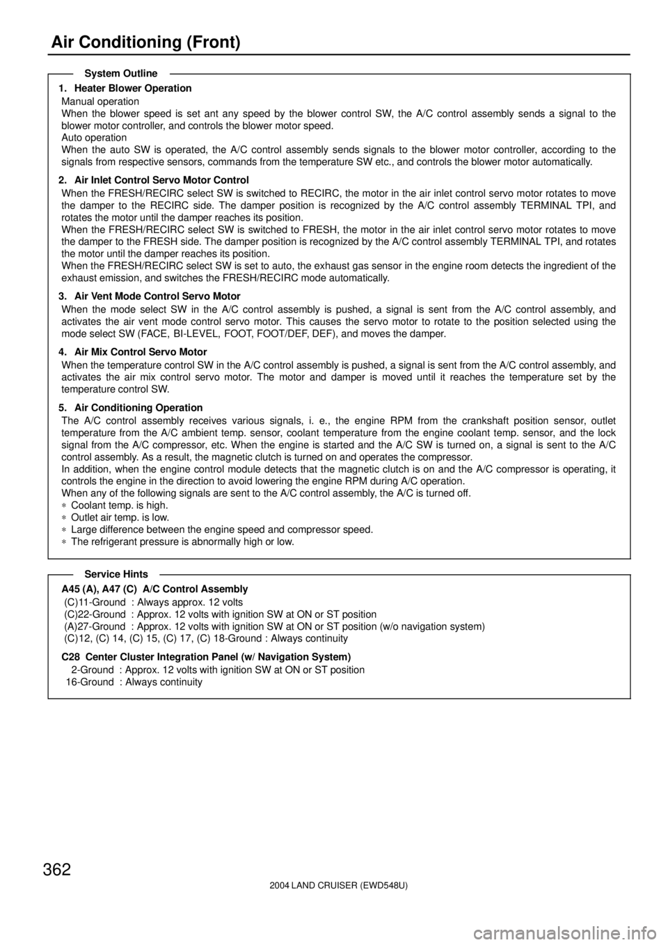
1. Heater Blower Operation
Manual operation
When the blower speed is set ant any speed by the blower control SW, the A/C control assembly sends a signal to the
blower motor controller, and controls the blower motor speed.
Auto operation
When the auto SW is operated, the A/C control assembly sends signals to the blower motor controller, according to the
signals from respective sensors, commands from the temperature SW etc., and controls the blower motor automatically.
2. Air Inlet Control Servo Motor Control
When the FRESH/RECIRC select SW is switched to RECIRC, the motor in the air inlet control servo motor rotates to move
the damper to the RECIRC side. The damper position is recognized by the A/C control assembly TERMINAL TPI, and
rotates the motor until the damper reaches its position.
When the FRESH/RECIRC select SW is switched to FRESH, the motor in the air inlet control servo motor rotates to move
the damper to the FRESH side. The damper position is recognized by the A/C control assembly TERMINAL TPI, and rotates
the motor until the damper reaches its position.
When the FRESH/RECIRC select SW is set to auto, the exhaust gas sensor in the engine room detects the ingredient of the
exhaust emission, and switches the FRESH/RECIRC mode automatically.
3. Air Vent Mode Control Servo Motor
When the mode select SW in the A/C control assembly is pushed, a signal is sent from the A/C control assembly, and
activates the air vent mode control servo motor. This causes the servo motor to rotate to the position selected using the
mode select SW (FACE, BI-LEVEL, FOOT, FOOT/DEF, DEF), and moves the damper.
4. Air Mix Control Servo Motor
When the temperature control SW in the A/C control assembly is pushed, a signal is sent from the A/C control assembly, and
activates the air mix control servo motor. The motor and damper is moved until it reaches the temperature set by the
temperature control SW.
5. Air Conditioning Operation
The A/C control assembly receives various signals, i. e., the engine RPM from the crankshaft position sensor, outlet
temperature from the A/C ambient temp. sensor, coolant temperature from the engine coolant temp. sensor, and the lock
signal from the A/C compressor, etc. When the engine is started and the A/C SW is turned on, a signal is sent to the A/C
control assembly. As a result, the magnetic clutch is turned on and operates the compressor.
In addition, when the engine control module detects that the magnetic clutch is on and the A/C compressor is operating, it
controls the engine in the direction to avoid lowering the engine RPM during A/C operation.
When any of the following signals are sent to the A/C control assembly, the A/C is turned off.
*Coolant temp. is high.
*Outlet air temp. is low.
*Large difference between the engine speed and compressor speed.
*The refrigerant pressure is abnormally high or low.
A45 (A), A47 (C) A/C Control Assembly
(C)11-Ground : Always approx. 12 volts
(C)22-Ground : Approx. 12 volts with ignition SW at ON or ST position
(A)27-Ground : Approx. 12 volts with ignition SW at ON or ST position (w/o navigation system)
(C) 12, (C) 14, (C) 15, (C) 17, (C) 18-Ground : Always continuity
C28 Center Cluster Integration Panel (w/ Navigation System)
2-Ground : Approx. 12 volts with ignition SW at ON or ST position
16-Ground : Always continuity
System Outline
Service Hints
Page 2390 of 3115
IG08V-01
B04078
IG-10
- IGNITIONCAMSHAFT POSITION SENSOR
1813 Author�: Date�:
2004 LAND CRUISER (RM1071U)
INSTALLATION
1. INSTALL CAMSHAFT POSITION SENSOR
Install the camshaft position sensor with the bolt and stud bolt
Torque: 7.5 N´m (80 kgf´cm, 66 in.´lbf)
2. INSTALL LH NO.3 TIMING BELT COVER
(See page EM-22)
3. CONNECT RADIATOR HOSE
4. INSTALL V-BANK COVER
5. FILL ENGINE COOLANT (See page CO-2)
6. CHECK ENGINE COOLANT FOR LEAKS
7. CHECK IGNITION TIMING (See page EM-9)
Page 2391 of 3115
IG08U-01
B04078
- IGNITIONCAMSHAFT POSITION SENSOR
IG-9
1812 Author�: Date�:
2004 LAND CRUISER (RM1071U)
REMOVAL
1. REMOVE V-BANK COVER
2. DRAIN ENGINE COOLANT
3. DISCONNECT UPPER RADIATOR HOSE
4. REMOVE LH NO.3 TIMING BELT COVER
(See page EM-15)
5. REMOVE CAMSHAFT POSITION SENSOR
Remove the bolt, stud bolt and camshaft position sensor.
Page 2424 of 3115

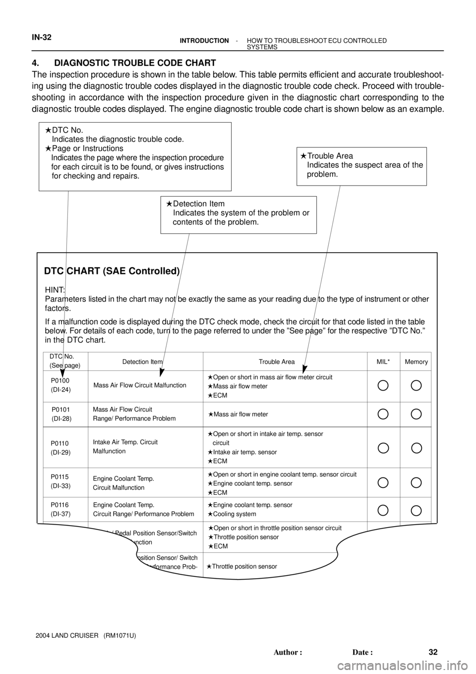
� DTC No.
Indicates the diagnostic trouble code.
� Page or Instructions
Indicates the page where the inspection procedure
for each circuit is to be found, or gives instructions
for checking and repairs.
� Detection Item
Indicates the system of the problem or
contents of the problem.� Trouble Area
Indicates the suspect area of the
problem.
Mass Air Flow Circuit MalfunctionDetection Item
� Open or short in mass air flow meter circuit
� Mass air flow meter
� ECM DTC No.
(See page)Trouble AreaMIL* MemoryP0100
(DI-24)
P0101
(DI-28)
P0115
(DI-33)� Open or short in intake air temp. sensor
circuit
� Intake air temp. sensor
� ECM Intake Air Temp. Circuit
Malfunction P0110
(DI-29)
� Open or short in engine coolant temp. sensor circuit
� Engine coolant temp. sensor
� ECM
P0120
Throttle/ Pedal Position Sensor/Switch
ºAº Circuit MalfunctionEngine Coolant Temp.
Circuit Malfunction
� Open or short in throttle position sensor circuit
� Throttle position sensor
� ECM
DTC CHART (SAE Controlled)
HINT:
Parameters listed in the chart may not be exactly the same as your reading due to the type of instrument or other
factors.
If a malfunction code is displayed during the DTC check mode, check the circuit for that code listed in the table
below. For details of each code, turn to the page referred to under the ºSee pageº for the respective ºDTC No.º
in the DTC chart.
Mass Air Flow Circuit
Range/ Performance Problem� Mass air flow meter
� Throttle position sensor Throttle/ Pedal Position Sensor/ Switch
ºAº Circuit Range / Performance Prob-
lem P0116
(DI-37)Engine Coolant Temp.
Circuit Range/ Performance Problem� Engine coolant temp. sensor
� Cooling system
IN-32- INTRODUCTIONHOW TO TROUBLESHOOT ECU CONTROLLED
SYSTEMS
32 Author�: Date�:
2004 LAND CRUISER (RM1071U)
4. DIAGNOSTIC TROUBLE CODE CHART
The inspection procedure is shown in the table below. This table permits efficient and accurate troubleshoot-
ing using the diagnostic trouble codes displayed in the diagnostic trouble code check. Proceed with trouble-
shooting in accordance with the inspection procedure given in the diagnostic chart corresponding to the
diagnostic trouble codes displayed. The engine diagnostic trouble code chart is shown below as an example.
Page 2453 of 3115
LU08Z-08
B04611
New O-Ring
B04612
LU-22
- LUBRICATIONOIL COOLER
1803 Author�: Date�:
2004 LAND CRUISER (RM1071U)
INSTALLATION
1. INSTALL OIL COOLER
(a) Clean the oil cooler contact surface on the cooler mount-
ing.
(b) Install a new O-ring to the oil cooler.
(c) Apply a light coat of engine oil on the threads and under
the head of the union bolt.
(d) Install the plate washer and union bolt.
Torque: 68.6 N´m (700 kgf´cm, 51 ft´lbf)
(e) Connect the 2 oil cooler hoses to the oil cooler.
2. INSTALL OIL FILTER (See page LU-2)
3. FILL WITH ENGINE COOLANT
4. START ENGINE AND CHECK FOR ENGINE OIL
LEAKS
5. CHECK ENGINE OIL LEVEL
Page 2454 of 3115
LU08X-06
B04612
LU-20
- LUBRICATIONOIL COOLER
1801 Author�: Date�:
2004 LAND CRUISER (RM1071U)
REMOVAL
1. DRAIN ENGINE COOLANT
2. REMOVE OIL FILTER (See page LU-2)
3. REMOVE OIL COOLER
(a) Disconnect the 2 oil cooler hoses from the oil cooler.
(b) Remove the union bolt, plate washer and the oil cooler.
(c) Remove the O-ring from the oil cooler.
Page 2475 of 3115
MA02S-01
MA-6
- MAINTENANCEENGINE
54 Author�: Date�:
2004 LAND CRUISER (RM1071U)
ENGINE
INSPECTION
HINT:
Inspect these items when the engine is cold.
1. REPLACE TIMING BELT (See page EM-15)
2. INSPECT VALVE CLEARANCE (See page EM-4)
3. INSPECT DRIVE BELT (See page CH-2)
4. REPLACE ENGINE OIL AND OIL FILTER (See page LU-2)
5. REPLACE ENGINE COOLANT (See page CO-2)
6. INSPECT EXHAUST PIPES AND MOUNTINGS
Visually inspect the pipes, hangers and connections for severe corrosion, leaks or damage.
7. REPLACE AIR CLEANER FILTER
Replace the air cleaner filter with a new one.
8. INSPECT FUEL LINES, CONNECTIONS AND FUEL VAPOR CONTROL VALVE (See page
EC-5)
Visually inspect the fuel lines for cracks, leakage loose connections, deformation or tank band looseness.
9. INSPECT GASKET IN FUEL TANK CAP (See page EC-5)
10. REPLACE SPARK PLUGS (See page IG-1)
11. California, Massachusetts and New York:
INSPECT CHARCOAL CANISTER (See page EC-5)
Page 2479 of 3115

MA02R-05
MA-4
- MAINTENANCEUNDER HOOD
52 Author�: Date�:
2004 LAND CRUISER (RM1071U)
UNDER HOOD
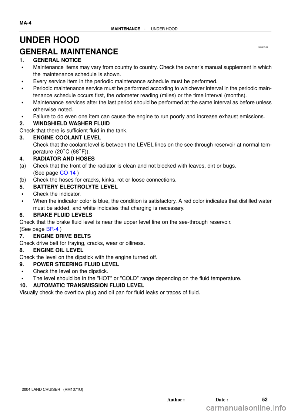
GENERAL MAINTENANCE
1. GENERAL NOTICE
�Maintenance items may vary from country to country. Check the owner's manual supplement in which
the maintenance schedule is shown.
�Every service item in the periodic maintenance schedule must be performed.
�Periodic maintenance service must be performed according to whichever interval in the periodic main-
tenance schedule occurs first, the odometer reading (miles) or the time interval (months).
�Maintenance services after the last period should be performed at the same interval as before unless
otherwise noted.
�Failure to do even one item can cause the engine to run poorly and increase exhaust emissions.
2. WINDSHIELD WASHER FLUID
Check that there is sufficient fluid in the tank.
3. ENGINE COOLANT LEVEL
Check that the coolant level is between the LEVEL lines on the see-through reservoir at normal tem-
perature (20°C (68°F)).
4. RADIATOR AND HOSES
(a) Check that the front of the radiator is clean and not blocked with leaves, dirt or bugs.
(See page CO-14)
(b) Check the hoses for cracks, kinks, rot or loose connections.
5. BATTERY ELECTROLYTE LEVEL
�Check the indicator.
�When the indicator color is blue, the condition is satisfactory. A red color indicates that distilled water
must be added, and white indicates that charging is necessary.
6. BRAKE FLUID LEVELS
Check that the brake fluid level is near the upper level line on the see-through reservoir.
(See page BR-4)
7. ENGINE DRIVE BELTS
Check drive belt for fraying, cracks, wear or oiliness.
8. ENGINE OIL LEVEL
Check the level on the dipstick with the engine turned off.
9. POWER STEERING FLUID LEVEL
�Check the level on the dipstick.
�The level should be in the ºHOTº or ºCOLDº range depending on the fluid temperature.
10. AUTOMATIC TRANSMISSION FLUID LEVEL
Visually check the overflow plug and oil pan for fluid leaks or traces of fluid.