Page 1818 of 3115

14. INSTALL REAR OIL SEAL RETAINER")
A04848
Seal Width
2 - 3 mm A
BA
B
A04855
New O-Ring
P12477
Seal Packing EM-1 12
- ENGINE MECHANICALCYLINDER BLOCK
1685 Author�: Date�:
2004 LAND CRUISER (RM1071U)
14. INSTALL REAR OIL SEAL RETAINER
(a) Remove any old packing (FIPG) material, and be careful
not to drop any oil on the contact surfaces of the oil seal
retainer and the cylinder block.
�Using a razor blade and a gasket scraper, remove
old FIPG from the seal surface.
�Clean all the components to remove the redundant
FIPG completely.
�Clean sealing surfaces with solvent so that any resi-
due does not remain on the seal.
(b) Apply seal packing to the oil seal retainer as shown in the
illustration.
Seal packing: Part No. 08826-00080 or equivalent
�Install a nozzle that is cut to a 2 - 3 mm (0.08 - 0.12
in.) opening.
�Parts must be assembled within 5 minutes after the
seal packing application. Otherwise the material
must be removed and the seal packing have to be
reapplied.
�Immediately remove the nozzle from the tube and
reinstall the cap.
(c) Install a new O-ring to the cylinder block.
(d) Install the oil seal retainer with the 7 bolts.
Torque: 8.0 N´m (80 kgf´cm, 71 in.´lbf)
15. INSTALL ENGINE COOLANT DRAIN UNIONS
(a) Apply seal packing to 2 or 3 threads from the end of the
drain unions.
Seal packing: Part No. 08826-00100 or equivalent
Page 1856 of 3115

REMOVAL
1. DRAIN ENGINE COOLANT
2. REMOVE V-BANK COVER
Remove the V-bank covers.
3. DISCONNECT")
EM1V8-01
A02844
- ENGINE MECHANICALCYLINDER HEAD
EM-35
1608 Author�: Date�:
2004 LAND CRUISER (RM1071U)
REMOVAL
1. DRAIN ENGINE COOLANT
2. REMOVE V-BANK COVER
Remove the V-bank covers.
3. DISCONNECT TIMING BELT FROM CAMSHAFT TIM-
ING PULLEYS (See page EM-15)
4. REMOVE CAMSHAFT TIMING PULLEYS (See page
EM-15)
5. REMOVE CAMSHAFT POSITION SENSOR (See page
IG-9)
6. DISCONNECT PS PUMP FROM ENGINE
(See page EM-77)
7. REMOVE FRONT EXHAUST PIPE (See page EM-1 15)
8. REMOVE OIL DIPSTICK AND GUIDE FOR A/T
9. REMOVE IGNITION COILS (See page IG-6)
10. REMOVE TIMING BELT REAR PLATES
(1) Remove the 3 bolts, the stud bolt, and the RH No.1
timing belt rear plates.
(2) Disconnect the wire clamp from the LH timing belt
rear plate.
(3) Remove the 3 bolts, the stud bolt, the LH No.1 and
the timing belt rear plates.
NOTICE:
�Be careful not to drop anything inside the timing belt
cover.
�Do not allow the belt to contact correct with oil, water
or dust.
11. DISCONNECT FUEL INLET HOSE (See page SF-24)
12. REMOVE INTAKE MANIFOLD ASSEMBLY
(a) Disconnect the throttle control connector.
(b) Disconnect the VSV connector for EVAP.
(c) Disconnect the 8 injector connectors.
(d) Disconnect the ECT sensor connector.
(e) Disconnect the water sender gauge connector.
(f) Disconnect the 8 ignition coil connectors.
(g) Disconnect the 2 oxygen sensor connectors.
Page 1877 of 3115
- ENGINE MECHANICALENGINE UNIT
EM-85
1658 Author�: Date�:
2004 LAND CRUISER (RM1071U)
(h) Connect the upper radiator hose to the front water bypass
joint.
17. INSTALL RADIATOR RESERVOIR
(a) Install the grommet to the reservoir.
(b) Attach the lower side of the reservoir to the fan shroud.
(c) Install the reservoir with the 2 bolts.
(d) Connect the reservoir hose to the radiator.
(e) Install the clamp on the wire to the reservoir.
18. INSTALL AIR CLEANER CAP AND INTAKE AIR CON-
NECTOR PIPE ASSEMBLY
19. INSTALL BATTERY
20. FILL WITH ENGINE COOLANT (See page CO-2)
21. FILL WITH ENGINE OIL (See page LU-2)
22. START ENGINE AND CHECK FOR LEAKS
23. INSTALL V-BANK COVER
24. INSTALL ENGINE UNDER COVERS
25. INSTALL HOOD
26. PERFORM ROAD TEST
Check for abnormal noise, shock, slippage, and make sure the
shift points is correct and operation is smooth.
27. RECHECK ENGINE COOLANT AND OIL LEVELS
Page 1878 of 3115

REMOVAL
1. REMOVE HOOD
2. REMOVE ENGINE UNDER COVERS
3. DRAIN ENGINE COOLANT
4. DRAIN ENGINE OIL
5. REM")
EM0L9-07
- ENGINE MECHANICALENGINE UNIT
EM-77
1650 Author�: Date�:
2004 LAND CRUISER (RM1071U)
REMOVAL
1. REMOVE HOOD
2. REMOVE ENGINE UNDER COVERS
3. DRAIN ENGINE COOLANT
4. DRAIN ENGINE OIL
5. REMOVE V-BANK COVER
6. REMOVE BATTERY
7. REMOVE AIR CLEANER CAP AND INTAKE AIR CON-
NECTOR PIPE ASSEMBLY
8. REMOVE RADIATOR RESERVOIR
(a) Disconnect the clamp on the wire from the reservoir.
(b) Disconnect the reservoir hose from the radiator.
(c) Remove the 2 bolts, the reservoir and the grommet.
9. REMOVE RADIATOR AND FAN SHROUD
(a) Disconnect the upper radiator hose from the front water
bypass joint.
(b) Remove the 2 nuts, and disconnect the 2 clamps on the
A/C discharge tube from the bracket.
(c) Remove the 2 bolts, and disconnect the 2 brackets on the
wire from the radiator.
(d) Remove the 3 bolts, and disconnect the fan shroud from
the radiator.
(e) Remove the lower radiator hose.
(f) Disconnect the 2 A/T oil cooler hoses from the radiator.
(g) Remove the 2 bolts, the 2 nuts, the 2 support collars and
the radiator.
(h) Remove the fan shroud.
10. REMOVE GENERATOR DRIVE BELT, FAN, FLUID
COUPLING AND FAN PULLEY
(a) Loosen the 4 nuts holding the fluid coupling to the fan
bracket.
(b) Remove the generator drive belt. (See page CH-7)
(c) Remove the 4 nuts, the fan, the fluid coupling assembly
and the fan pulley.
11. DISCONNECT ENGINE WIRE FROM CABIN
(a) Remove the glove compartment door.
(b) Remove the lower No.2 panel.
(c) Disconnect the 3 connectors from the ECM.
(d) Remove the 3 screws, and disconnect ECM from the
body bracket.
(e) Disconnect the 3 wire harness connectors.
12. DISCONNECT HOSES, WIRES, CONNECTORS,
CLAMPS, GROMMET AND CABLES
(a) Disconnect the 2 PS air hoses from the hose clamp on the
No.3 RH timing belt cover.
(b) Disconnect the generator wire.
(c) Disconnect the generator connector.
(d) Disconnect the hose clamp for PS air hose.
(e) Disconnect the PS air hose from upper intake manifold.
Page 1896 of 3115
A02247
- ENGINE MECHANICALTIMING BELT
EM-27
1600 Author�: Date�:
2004 LAND CRUISER (RM1071U)
25. INSTALL FAN PULLEY, FAN, FLUID COUPLING
AND DRIVE BELT
(a) Temporarily install the fan pulley, the fan, fluid coupling
assembly with the 4 nuts.
(b) Install the generator drive belt.
(See page CH-16)
(c) Tighten the 4 nuts holding the fluid coupling to the fan
bracket.
Torque: 21 N´m (215 kgf´cm, 16 ft´lbf)
26. INSTALL AIR CLEANER AND INTAKE AIR
CONNECTOR ASSEMBLY
27. INSTALL V-BANK COVER
28. FILL WITH ENGINE COOLANT
29. START ENGINE AND CHECK FOR LEAKS
30. RECHECK ENGINE COOLANT LEVEL
31. INSTALL BATTERY CLAMP COVER
32. INSTALL ENGINE UNDER COVER
33. INSTALL OIL PAN PROTECTOR
Page 1897 of 3115
EM1VA-01
A02247
A04329
- ENGINE MECHANICALTIMING BELT
EM-15
1588 Author�: Date�:
2004 LAND CRUISER (RM1071U)
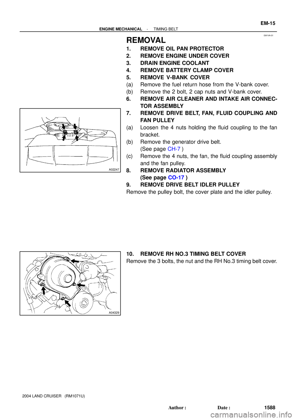
REMOVAL
1. REMOVE OIL PAN PROTECTOR
2. REMOVE ENGINE UNDER COVER
3. DRAIN ENGINE COOLANT
4. REMOVE BATTERY CLAMP COVER
5. REMOVE V-BANK COVER
(a) Remove the fuel return hose from the V-bank cover.
(b) Remove the 2 bolt, 2 cap nuts and V-bank cover.
6. REMOVE AIR CLEANER AND INTAKE AIR CONNEC-
TOR ASSEMBLY
7. REMOVE DRIVE BELT, FAN, FLUID COUPLING AND
FAN PULLEY
(a) Loosen the 4 nuts holding the fluid coupling to the fan
bracket.
(b) Remove the generator drive belt.
(See page CH-7)
(c) Remove the 4 nuts, the fan, the fluid coupling assembly
and the fan pulley.
8. REMOVE RADIATOR ASSEMBLY
(See page CO-17)
9. REMOVE DRIVE BELT IDLER PULLEY
Remove the pulley bolt, the cover plate and the idler pulley.
10. REMOVE RH NO.3 TIMING BELT COVER
Remove the 3 bolts, the nut and the RH No.3 timing belt cover.
Page 1902 of 3115

VALVE CLEARANCE
INSPECTION
HINT:
Inspect and adjust the valve clearance when the engi")
EM0KS-08
A04324
A04325
EM-4
- ENGINE MECHANICALVALVE CLEARANCE
1577 Author�: Date�:
2004 LAND CRUISER (RM1071U)
VALVE CLEARANCE
INSPECTION
HINT:
Inspect and adjust the valve clearance when the engine is cold.
1. DRAIN ENGINE COOLANT
2. REMOVE BATTERY CLAMP COVER
3. REMOVE V-BANK COVER
4. REMOVE AIR CLEANER AND INTAKE AIR CONNEC-
TOR ASSEMBLY
5. REMOVE NO.3 TIMING BELT COVERS
(See page EM-15)
6. REMOVE IGNITION COILS (See page IG-6)
7. REMOVE RH CYLINDER HEAD COVER
Remove the 9 bolts, the 9 seal washers and the cylinder head
cover.
8. REMOVE LH CYLINDER HEAD COVER
(a) Remove the oil dipstick for the transmission.
(b) Disconnect the PCV hose.
(c) Disconnect the engine wire clamp from the wire bracket
on the cylinder head cover.
(d) Remove the 9 bolts, the 9 seal washers and the cylinder
head cover.
9. SET NO.1 CYLINDER TO TDC/COMPRESSION
(a) Turn the crankshaft pulley, and align its groove with timing
mark º0º of the No.1 timing belt cover.
(b) Check that the timing marks of the camshaft timing pul-
leys and that of the timing belt rear plates are aligned.
If not, turn the crankshaft 1 revolution (360°) and align the mark
as above.
Page 1904 of 3115
EM-6
- ENGINE MECHANICALVALVE CLEARANCE
1579 Author�: Date�:
2004 LAND CRUISER (RM1071U)
Intake:
N = T + (A - 0.20 mm (0.008 in.))
Exhaust:
N = T + (A - 0.30 mm (0.012 in.))
�Select a new shim with the closest thickness as
close as possible to the calculated value.
HINT:
Shims are available in 41 increments of 0.020 mm (0.0008 in.),
from 2.00 mm (0.0787 in.) to 2.80 mm (0.1102 in.).
(e) Place a new adjusting shim on the valve.
(f) Place the valve lifter.
(g) Reinstall the camshafts (See page EM-57).
(h) Reinstall the timing belt (See page EM-22).
(i) Recheck the valve clearance.
12. REINSTALL CYLINDER HEAD COVERS
13. REINSTALL IGNITION COILS
14. REINSTALL NO.3 TIMING BELT COVERS (See page
EM-22)
15. REINSTALL AIR CLEANER AND INTAKE AIR CON-
NECTOR ASSEMBLY
16. REFILL WITH ENGINE COOLANT
17. START ENGINE AND CHECK FOR LEAKS
18. RECHECK ENGINE COOLANT LEVEL
19. REINSTALL V-BANK COVER
20. REINSTALL BATTERY CLAMP COVER