1998 OPEL FRONTERA G-Sensor
[x] Cancel search: G-SensorPage 811 of 6000
5A–1 BRAKE CONTROL SYSTEM
BRAKES
CONTENTS
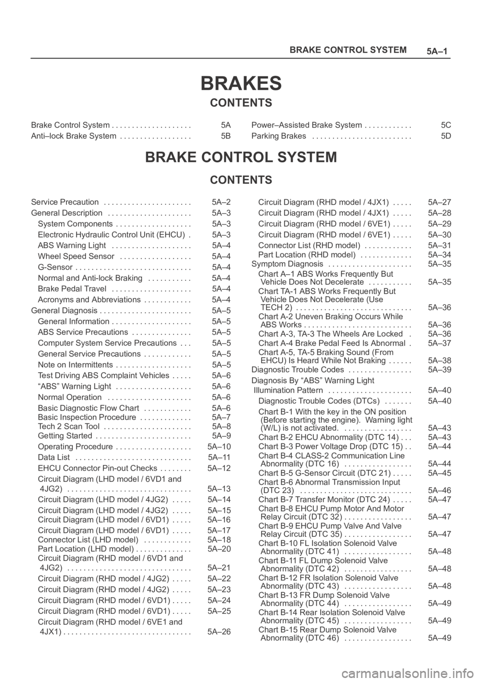
Brake Control System 5A. . . . . . . . . . . . . . . . . . . .
Anti–lock Brake System 5B. . . . . . . . . . . . . . . . . . Power–Assisted Brake System 5C. . . . . . . . . . . .
Parking Brakes 5D. . . . . . . . . . . . . . . . . . . . . . . . .
BRAKE CONTROL SYSTEM
CONTENTS
Service Precaution 5A–2. . . . . . . . . . . . . . . . . . . . . .
General Description 5A–3. . . . . . . . . . . . . . . . . . . . .
System Components 5A–3. . . . . . . . . . . . . . . . . . .
Electronic Hydraulic Control Unit (EHCU) 5A–3.
ABS Warning Light 5A–4. . . . . . . . . . . . . . . . . . . .
Wheel Speed Sensor 5A–4. . . . . . . . . . . . . . . . . .
G-Sensor 5A–4. . . . . . . . . . . . . . . . . . . . . . . . . . . . .
Normal and Anti-lock Braking 5A–4. . . . . . . . . . .
Brake Pedal Travel 5A–4. . . . . . . . . . . . . . . . . . . .
Acronyms and Abbreviations 5A–4. . . . . . . . . . . .
General Diagnosis 5A–5. . . . . . . . . . . . . . . . . . . . . . .
General Information 5A–5. . . . . . . . . . . . . . . . . . . .
ABS Service Precautions 5A–5. . . . . . . . . . . . . . .
Computer System Service Precautions 5A–5. . .
General Service Precautions 5A–5. . . . . . . . . . . .
Note on Intermittents 5A–5. . . . . . . . . . . . . . . . . . .
Test Driving ABS Complaint Vehicles 5A–6. . . . .
“ABS” Warning Light 5A–6. . . . . . . . . . . . . . . . . . .
Normal Operation 5A–6. . . . . . . . . . . . . . . . . . . . .
Basic Diagnostic Flow Chart 5A–6. . . . . . . . . . . .
Basic Inspection Procedure 5A–7. . . . . . . . . . . . .
Tech 2 Scan Tool 5A–8. . . . . . . . . . . . . . . . . . . . . .
Getting Started 5A–9. . . . . . . . . . . . . . . . . . . . . . . .
Operating Procedure 5A–10. . . . . . . . . . . . . . . . . . .
Data List 5A–11. . . . . . . . . . . . . . . . . . . . . . . . . . . . .
EHCU Connector Pin-out Checks 5A–12. . . . . . . .
Circuit Diagram (LHD model / 6VD1 and
4JG2) 5A–13. . . . . . . . . . . . . . . . . . . . . . . . . . . . . . .
Circuit Diagram (LHD model / 4JG2) 5A–14. . . . .
Circuit Diagram (LHD model / 4JG2) 5A–15. . . . .
Circuit Diagram (LHD model / 6VD1) 5A–16. . . . .
Circuit Diagram (LHD model / 6VD1) 5A–17. . . . .
Connector List (LHD model) 5A–18. . . . . . . . . . . .
Part Location (LHD model) 5A–20. . . . . . . . . . . . . .
Circuit Diagram (RHD model / 6VD1 and
4JG2) 5A–21. . . . . . . . . . . . . . . . . . . . . . . . . . . . . . .
Circuit Diagram (RHD model / 4JG2) 5A–22. . . . .
Circuit Diagram (RHD model / 4JG2) 5A–23. . . . .
Circuit Diagram (RHD model / 6VD1) 5A–24. . . . .
Circuit Diagram (RHD model / 6VD1) 5A–25. . . . .
Circuit Diagram (RHD model / 6VE1 and
4JX1) 5A–26. . . . . . . . . . . . . . . . . . . . . . . . . . . . . . . . Circuit Diagram (RHD model / 4JX1) 5A–27. . . . .
Circuit Diagram (RHD model / 4JX1) 5A–28. . . . .
Circuit Diagram (RHD model / 6VE1) 5A–29. . . . .
Circuit Diagram (RHD model / 6VE1) 5A–30. . . . .
Connector List (RHD model) 5A–31. . . . . . . . . . . .
Part Location (RHD model) 5A–34. . . . . . . . . . . . .
Symptom Diagnosis 5A–35. . . . . . . . . . . . . . . . . . . . .
Chart A–1 ABS Works Frequently But
Vehicle Does Not Decelerate 5A–35. . . . . . . . . . .
Chart TA-1 ABS Works Frequently But
Vehicle Does Not Decelerate (Use
TECH 2) 5A–36. . . . . . . . . . . . . . . . . . . . . . . . . . . . .
Chart A-2 Uneven Braking Occurs While
ABS Works 5A–36. . . . . . . . . . . . . . . . . . . . . . . . . . .
Chart A-3, TA-3 The Wheels Are Locked 5A–36.
Chart A-4 Brake Pedal Feed Is Abnormal 5A–37.
Chart A-5, TA-5 Braking Sound (From
EHCU) Is Heard While Not Braking 5A–38. . . . . .
Diagnostic Trouble Codes 5A–39. . . . . . . . . . . . . . . .
Diagnosis By “ABS” Warning Light
Illumination Pattern 5A–40. . . . . . . . . . . . . . . . . . . . .
Diagnostic Trouble Codes (DTCs) 5A–40. . . . . . .
Chart B-1 With the key in the ON position
(Before starting the engine). Warning light
(W/L) is not activated. 5A–43. . . . . . . . . . . . . . . . .
Chart B-2 EHCU Abnormality (DTC 14) 5A–43. . .
Chart B-3 Power Voltage Drop (DTC 15) 5A–44. .
Chart B-4 CLASS-2 Communication Line
Abnormality (DTC 16) 5A–44. . . . . . . . . . . . . . . . .
Chart B-5 G-Sensor Circuit (DTC 21) 5A–45. . . . .
Chart B-6 Abnormal Transmission Input
(DTC 23) 5A–46. . . . . . . . . . . . . . . . . . . . . . . . . . . .
Chart B-7 Transfer Monitor (DTC 24) 5A–47. . . . .
Chart B-8 EHCU Pump Motor And Motor
Relay Circuit (DTC 32) 5A–47. . . . . . . . . . . . . . . . .
Chart B-9 EHCU Pump Valve And Valve
Relay Circuit (DTC 35) 5A–47. . . . . . . . . . . . . . . . .
Chart B-10 FL Isolation Solenoid Valve
Abnormality (DTC 41) 5A–48. . . . . . . . . . . . . . . . .
Chart B-11 FL Dump Solenoid Valve
Abnormality (DTC 42) 5A–48. . . . . . . . . . . . . . . . .
Chart B-12 FR Isolation Solenoid Valve
Abnormality (DTC 43) 5A–48. . . . . . . . . . . . . . . . .
Chart B-13 FR Dump Solenoid Valve
Abnormality (DTC 44) 5A–49. . . . . . . . . . . . . . . . .
Chart B-14 Rear Isolation Solenoid Valve
Abnormality (DTC 45) 5A–49. . . . . . . . . . . . . . . . .
Chart B-15 Rear Dump Solenoid Valve
Abnormality (DTC 46) 5A–49. . . . . . . . . . . . . . . . .
Page 813 of 6000

5A–3 BRAKE CONTROL SYSTEM
General Description
The Anti-lock Brake System (ABS) works on all four
wheels. A combination of wheel speed sensor and
Electronic Hydraulic Control Unit (EHCU) can determine
when a wheel is about to stop turning and adjust brake
pressure to maintain best braking.This system helps the driver maintain greater control of
the vehicle under heavy braking conditions.
C05RW027
Legend
(1) With P&B Valve Model
(2) With LSPV Model
(3) Electronic Hydraulic Control Unit (EHCU)
(4) Front Wheel Speed Sensor
(5) Rear Wheel Speed Sensor(6) G-Sensor
(7) Proportioning and Bypass (P&B) Valve
(8) Load Sensing Proportioning Valve (LSPV)
(9) Electronic Line
(10) Hydraulic Line
System Components
Electronic Hydraulic Control Unit (EHCU), four Wheel
Speed Sensors, Warning Light, and G-sensor.
Electronic Hydraulic Control Unit (EHCU)
T h e E H C U c o n s i s t s o f A B S c o n t r o l c i r c u i t s , f a u l t d e t e c t o r,
and a fail-safe. It drives the hydraulic unit according to the
signal from each sensor, cancelling ABS to return to
Page 814 of 6000

5A–4
BRAKE CONTROL SYSTEM
normal braking when a malfunction has occurred in the
ABS.
The EHCU has a self-diagnosing function which can
indicate faulty circuits during diagnosis.
The EHCU is mounted on the engine compartment front
right side. It consists of a Motor, Plunger Pump, Solenoid
Valves and Check Valve.
On the outside, the relay box containing a motor relay and
a valve relay is installed.
Solenoid Valves: Reduces or holds the caliper fluid
pressure for each front disc brake or both rear disc brakes
according to the signal sent from the EHCU.
Reservoir: Temporarily holds the brake fluid that returns
from the front and rear disc brake caliper so that pressure
of front disc brake caliper can be reduced smoothly.
Plunger Pump: Feeds the brake fluid held in the reservoir
to the master cylinder.
Motor: Drives the pump according to the signal from
EHCU.
Check Valve: Controls the brake fluid flow.
ABS Warning Light
821RW033Vehicles equipped with the Anti-lock Brake System have
an amber “ABS” warning light in the instrument panel.
The “ABS” warning light will illuminate if a malfunction in
the Anti-lock Brake System is detected by the Electronic
Hydraulic Control Unit (EHCU). In case of an electronic
malfunction, the EHCU will turn “ON” the “ABS” warning
light and disable the Anti-lock braking function.
The “ABS” light will turn “ON” for approximately three
seconds after the ignition switch is to the “ON” position.
If the “ABS” light stays “ON” after the ignition switch is the
“ON” position, or comes “ON” and stays “ON” while
driving, the Anti-lock Brake System should be inspected
for a malfunction according to the diagnosis procedure.
Wheel Speed Sensor
It consists of a sensor and a rotor. The sensor is attached
to the knuckle on the front wheels and to the axle shaft
bearing holder on the rear wheels.
The rotor is press-fit in the axle shaft.The flux generated from electrodes magnetized by a
magnet in the sensor varies due to rotation of the rotor,
and the electromagnetic induction generates alternating
voltage in the coil. This voltage draws a “sine curve” with
the frequency proportional to rotor speed and it allows
detection of wheel speed.
G-Sensor
The G-sensor installed inside the center console detects
the vehicle deceleration speed and sends a signal to the
EHCU. In 4WD operation, all four wheels may be
decelerated in almost the same phase, since all wheels
are connected mechanically.
This tendency is noticeable particularly on roads with low
friction coefficient, and the ABS control is adversely
affected.
The G-sensor judges whether the friction coefficient of
road surface is low or high, and changes the EHCU’s
operating system to ensure ABS control.
Normal and Anti-lock Braking
Under normal driving conditions, the Anti-lock Brake
System functions the same as a standard power assisted
brake system. However, with the detection of wheel
lock-up, a slight bump or kick-back will be felt in the brake
pedal. This pedal “bump” will be followed by a series of
short pedal pulsations which occurs in rapid succession.
The brake pedal pulsation will continue until there is no
longer a need for the anti-lock function or until the vehicle
is stopped. A slight ticking or popping noise may be heard
during brake applications when the Anti-lock features is
being used.
When the Anti-lock feature is being used, the brake pedal
may rise even as the brakes are being applied. This is
also normal. Maintaining a constant force on the pedal
will provide the shortest stopping distance.
Brake Pedal Travel
Vehicles equipped with the Anti-lock Brake System may
be stopped by applying normal force to the brake pedal.
Although there is no need to push the pedal beyond the
point where it stops or holds the vehicle, by applying more
force the pedal will continue to travel toward the floor.
This extra brake pedal travel is normal.
Acronyms and Abbreviations
Several acronyms and abbreviations are commonly used
throughout this section:
ABS
Anti-lock Brake System
CKT
Circuit
DLC
Data Link Connector
EHCU
Electronic Hydraulic Control Unit
FL
Front Left
Page 821 of 6000

5A–11 BRAKE CONTROL SYSTEM
Data List
DisplayContentOK/NG Criteria for Data
Battery VoltageVo l t a g eBetween 10-16.9V
Brake Light SwitchOpen/CloseOpen(0V) when pedal is released
Closed(12V) when pedal is depressed.
Front Left Wheel Speed
Front Right Wheel Speed
Rear Left Wheel Speed
Rear Right Wheel SpeedMPH(km/h)Start the vehicle and make sure of linear change in each
wheel speed.
Turn each wheel by hand and make sure that each
speed data change.
Wheel Sensor StatusOK/NGTo be OK usually
G-sensorLow/HighTo be Low usually
Transfer Monitor(TOD)2 Wheel Drive
4 Wheel DriveWhen 2WD: 2 Wheel Drive
When 4WD: 4 Wheel Drive
Off-Road Switch
(Transmission Input)
Active/InactiveWhen shift lever position is 1, 2 and R: Active (M/T)
(Transmission Input)When shift lever position is L and R: Active (A/T)
Valve RelayActive/InactiveTo be Active usually
ABS StateON/OFFTo be OFF usually
ABS RelayActive/InactiveTo be Active usually
Return Pump RelayActive/InactiveTo be Inactive usually
Front Left Isolation ValveActive/InactiveTo be Inactive usually
Front Left Dump Valve
Front Right Isolation Valve
Front Right Dump Valve
Rear Isolation Valve
Rear Dump Valve
ABS Warning LampON/OFFTo be ON usually (while engine stopped)
Page 822 of 6000
5A–12
BRAKE CONTROL SYSTEM
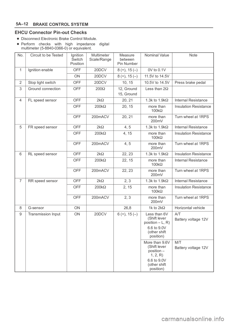
EHCU Connector Pin-out Checks
Disconnect Electronic Brake Control Module.
Perform checks with high impedance digital
multimeter (5-8840-0366-0) or equivalent.
No.
Circuit to be TestedIgnition
Switch
PositionMultimeter
Scale/RangeMeasure
between
Pin NumberNominal ValueNote
1Ignition enableOFF20DCV8 (+), 15 (–)0V to 0.1V
ON20DCV8 (+), 15 (–)11.5V to 14.5V
2Stop light switchOFF20DCV10, 1510.5V to 14.5VPress brake pedal
3Ground connectionOFF20012, Ground
15, GroundLess than 2
4FL speed sensorOFF2k20, 211.3k to 1.9kInternal Resistance
OFF200k20, 15more than
100kInsulation Resistance
OFF200mACV20, 21more than
200mVTurn wheel at 1RPS
5FR speed sensorOFF2k4, 51.3k to 1.9kInternal Resistance
OFF200k4, 15more than
100kInsulation Resistance
OFF200mACV4, 5more than
200mVTurn wheel at 1RPS
6RL speed sensorOFF2k22, 231.3k to 1.9kInsulation Resistance
OFF200k22, 15more than
100kInternal Resistance
OFF200mACV22, 23more than
200mVTurn wheel at 1RPS
7RR speed sensorOFF2k2, 31.3k to 1.9kInternal Resistance
OFF200k2, 15more than
100kInsulation Resistance
OFF200mACV2, 3more than
200mVTurn wheel at 1RPS
8G-sensorON26,81k to 2kHorizontal vehicle
9Transmission InputON20DCV6 (+), 15 (–)Less than 6V
(Shift lever
position – L, R)
6.6 to 9.0V
(other shift
position)A/T
Battery voltage 12V
More than 9.6V
(Shift lever
position –
1, 2, R)
6.6 to 9.0V
(other shift
position)M/T
Battery voltage 12V
Page 849 of 6000

5A–39 BRAKE CONTROL SYSTEM
Diagnostic Trouble Codes
Choose and trace an appropriate flowchart by the
numbers listed below to find fault and repair.
Code
ItemDiagnosisChart No.
12Start CodeNormal—
14EHCU FunctionAbnormality in input/output, operational and
control circuitsB-2
15Power Voltage DropB-3
16CLASS–2 Communication Line Ab-
normalityB-4
21G-sensorWiring disconnectionB-5
23Transmission InputInput abnormalityB-6
24Transfer MonitorB-7
32Motor & Motor RelayShorted or disconnected coilB-8
35Valve RelayShorted or disconnected coil/wiringB-9
41FL Holding Solenoid ValveShorted or disconnected coil/wiringB-10
42FL Decompression Solenoid ValveShorted or disconnected coil/wiringB-11
43FR Holding Solenoid ValveShorted or disconnected coil/wiringB-12
44FR Decompression Solenoid ValveShorted or disconnected coil/wiringB-13
45Rear Holding Solenoid ValveShorted or disconnected coil/wiringB-14
46Rear Decompression Solenoid ValveShorted or disconnected coil/wiringB-15
51FL Wheel Speed SensorDisconnected coil/wiringB-16
52FR Wheel Speed SensorDisconnected coil/wiringB-17
53RL Wheel Speed SensorDisconnected coil/wiringB-18
54RR Wheel Speed SensorDisconnected coil/wiringB-19
61FL Wheel Speed SensorShorted coil/wiringB-20
62FR Wheel Speed SensorShorted coil/wiringB-21
63RL Wheel Speed SensorShorted coil/wiringB-22
64RR Wheel Speed SensorShorted coil/wiringB-23
65Sensor Signal InputWrong number of teethB-24
Page 855 of 6000

5A–45 BRAKE CONTROL SYSTEM
Chart B-5 G-Sensor Circuit (DTC 21)
StepActionYe sNo
1Vehicle placed horizontal.
Is the resistance between the G sensor connector terminals 1 and
2 within 4.0-6.0 k
?
Check harness
connector for
short.
Fault found :
Repair , and
perform system
self-check.
No fault found :
replace EHCU.
Go to Step 3
Go to Step 2
2Is the bracket installed horizontally?
Go to Step 4
Repair or replace
bracket.
Go to Step 4
3Remove G sensor.
Is the resistance between the G sensor connector terminals 1 and
2 within 1.0-2.0 k
when G sensor is horizontal?Go to Step 4
Replace G
sensor.
Go to Step 5
4Measure resistance between G sensor connector terminals 1 and
2 within 4.0-6.0 k
when G sensor tilted to 30 or more?
Harness between
EHCU and G
sensor is faulty
and short.
Repair the
harness
Go to Step 5
Replace G
sensor.
Go to Step 5
51. Reconnect all components and ensure all components are
properly mounted.
2. Clear diagnostic trouble code.
Was this step finished?
Repeat the “Basic
diagnostic flow
chart.”
Go to Step 5
Page 873 of 6000

5B–1 ANTI–LOCK BRAKE SYSTEM
BRAKES
ANTI-LOCK BRAKE SYSTEM
CONTENTS
Service Precaution 5B–1. . . . . . . . . . . . . . . . . . . . . .
Electronic Hydraulic Control Unit 5B–2. . . . . . . . . .
Electronic Hydraulic Control Unit and
Associated Parts 5B–2. . . . . . . . . . . . . . . . . . . . . .
Removal 5B–2. . . . . . . . . . . . . . . . . . . . . . . . . . . . .
Installation 5B–2. . . . . . . . . . . . . . . . . . . . . . . . . . . .
G-Sensor 5B–3. . . . . . . . . . . . . . . . . . . . . . . . . . . . . .
Removal 5B–3. . . . . . . . . . . . . . . . . . . . . . . . . . . . .
Inspection and Repair 5B–3. . . . . . . . . . . . . . . . . .
Installation 5B–3. . . . . . . . . . . . . . . . . . . . . . . . . . . .
Front Wheel Speed Sensor 5B–4. . . . . . . . . . . . . . . Front Wheel Speed Sensor and
Associated Parts 5B–4. . . . . . . . . . . . . . . . . . . . . .
Removal 5B–4. . . . . . . . . . . . . . . . . . . . . . . . . . . . .
Inspection and Repair 5B–5. . . . . . . . . . . . . . . . . .
Installation 5B–5. . . . . . . . . . . . . . . . . . . . . . . . . . . .
Rear Wheel Speed Sensor 5B–6. . . . . . . . . . . . . . .
Rear Wheel Speed Sensor and
Associated Parts 5B–6. . . . . . . . . . . . . . . . . . . . . .
Removal 5B–6. . . . . . . . . . . . . . . . . . . . . . . . . . . . .
Inspection and Repair 5B–6. . . . . . . . . . . . . . . . . .
Installation 5B–6. . . . . . . . . . . . . . . . . . . . . . . . . . . .
Service Precaution
WARNING: IF SO EQUIPPED WITH A
SUPPLEMENTAL RESTRAINT SYSTEM(SRS),
REFER TO THE SRS COMPONENT AND WIRING
LOCATION VIEW IN ORDER TO DETERMINE
WHETHER YOU ARE PERFORMING SERVICE ON OR
NEAR THE SRS COMPONENTS OR THE SRS
WIRING. WHEN YOU ARE PERFORMING SERVICE
ON OR NEAR THE SRS COMPONENTS OR THE SRS
WIRING, REFER TO THE SRS SERVICE
INFORMATION. FAILURE TO FOLLOW WARNINGS
COULD RESULT IN POSSIBLE AIR BAG
DEPLOYMENT, PERSONAL INJURY, OR
OTHERWISE UNNEEDED SRS SYSTEM REPAIRS.
CAUTION: Always use the correct fastener in the
proper location. When you replace a fastener, use
ONLY the exact part number for that application.
ISUZU will call out those fasteners that require a
replacement after removal. ISUZU will also call out
the fasteners that require thread lockers or thread
sealant. UNLESS OTHERWISE SPECIFIED, do not
use supplemental coatings (Paints, greases, or other
corrosion inhibitors) on threaded fasteners or
fastener joint interfaces. Generally, such coatings
adversely affect the fastener torque and the joint
clamping force, and may damage the fastener. When
you install fasteners, use the correct tightening
sequence and specifications. Following these
instructions can help you avoid damage to parts and
systems.CAUTION: Replace all components included in
repair kits used to service this system. Lubricate
rubber parts with clean, fresh brake fluid to ease
assembly. Do not use shop air with in–line
lubricators on brake parts, as damage to rubber
components may result. If any hydraulic component
is removed or brake line disconnected, it may be
necessary to bleed part or all of the brake system.
NOTE: The use of rubber hoses or parts other than those
furnished specifically for the Anti–lock Brake System may
lead to functional problems requiring major overhaul.