5A–39 BRAKE CONTROL SYSTEM
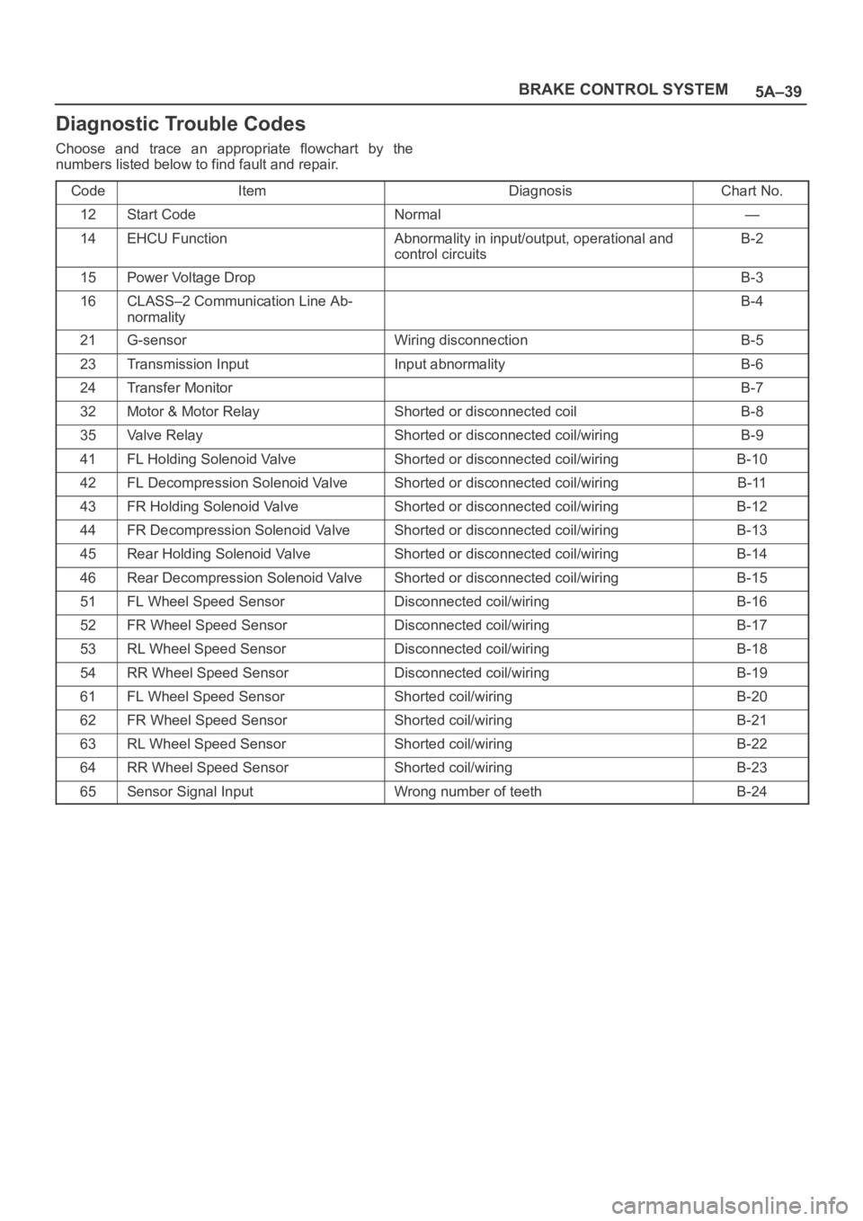
Diagnostic Trouble Codes
Choose and trace an appropriate flowchart by the
numbers listed below to find fault and repair.
Code
ItemDiagnosisChart No.
12Start CodeNormal—
14EHCU FunctionAbnormality in input/output, operational and
control circuitsB-2
15Power Voltage DropB-3
16CLASS–2 Communication Line Ab-
normalityB-4
21G-sensorWiring disconnectionB-5
23Transmission InputInput abnormalityB-6
24Transfer MonitorB-7
32Motor & Motor RelayShorted or disconnected coilB-8
35Valve RelayShorted or disconnected coil/wiringB-9
41FL Holding Solenoid ValveShorted or disconnected coil/wiringB-10
42FL Decompression Solenoid ValveShorted or disconnected coil/wiringB-11
43FR Holding Solenoid ValveShorted or disconnected coil/wiringB-12
44FR Decompression Solenoid ValveShorted or disconnected coil/wiringB-13
45Rear Holding Solenoid ValveShorted or disconnected coil/wiringB-14
46Rear Decompression Solenoid ValveShorted or disconnected coil/wiringB-15
51FL Wheel Speed SensorDisconnected coil/wiringB-16
52FR Wheel Speed SensorDisconnected coil/wiringB-17
53RL Wheel Speed SensorDisconnected coil/wiringB-18
54RR Wheel Speed SensorDisconnected coil/wiringB-19
61FL Wheel Speed SensorShorted coil/wiringB-20
62FR Wheel Speed SensorShorted coil/wiringB-21
63RL Wheel Speed SensorShorted coil/wiringB-22
64RR Wheel Speed SensorShorted coil/wiringB-23
65Sensor Signal InputWrong number of teethB-24
5A–45 BRAKE CONTROL SYSTEM
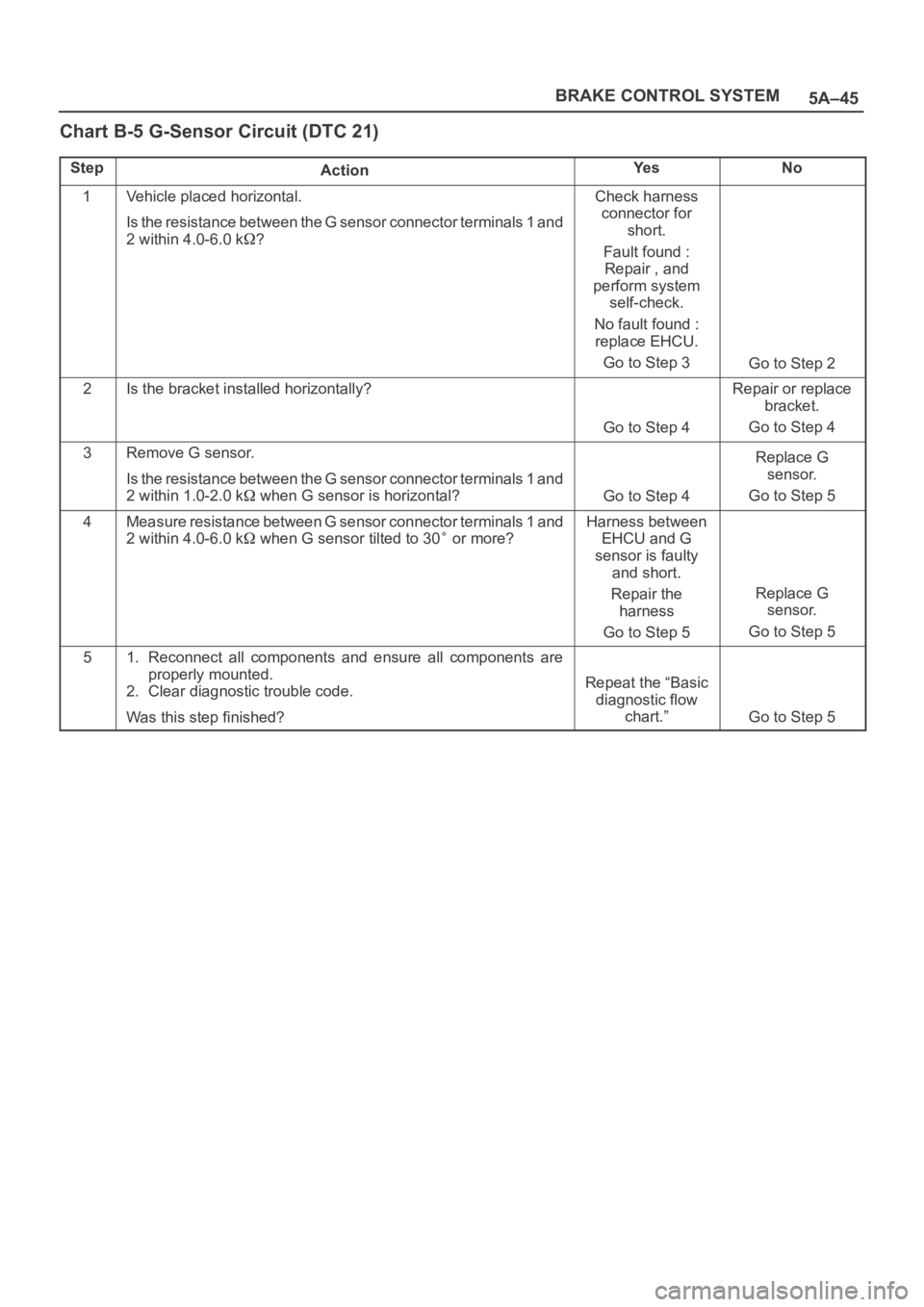
Chart B-5 G-Sensor Circuit (DTC 21)
StepActionYe sNo
1Vehicle placed horizontal.
Is the resistance between the G sensor connector terminals 1 and
2 within 4.0-6.0 k
?
Check harness
connector for
short.
Fault found :
Repair , and
perform system
self-check.
No fault found :
replace EHCU.
Go to Step 3
Go to Step 2
2Is the bracket installed horizontally?
Go to Step 4
Repair or replace
bracket.
Go to Step 4
3Remove G sensor.
Is the resistance between the G sensor connector terminals 1 and
2 within 1.0-2.0 k
when G sensor is horizontal?Go to Step 4
Replace G
sensor.
Go to Step 5
4Measure resistance between G sensor connector terminals 1 and
2 within 4.0-6.0 k
when G sensor tilted to 30 or more?
Harness between
EHCU and G
sensor is faulty
and short.
Repair the
harness
Go to Step 5
Replace G
sensor.
Go to Step 5
51. Reconnect all components and ensure all components are
properly mounted.
2. Clear diagnostic trouble code.
Was this step finished?
Repeat the “Basic
diagnostic flow
chart.”
Go to Step 5
5B–1 ANTI–LOCK BRAKE SYSTEM
BRAKES
ANTI-LOCK BRAKE SYSTEM
CONTENTS
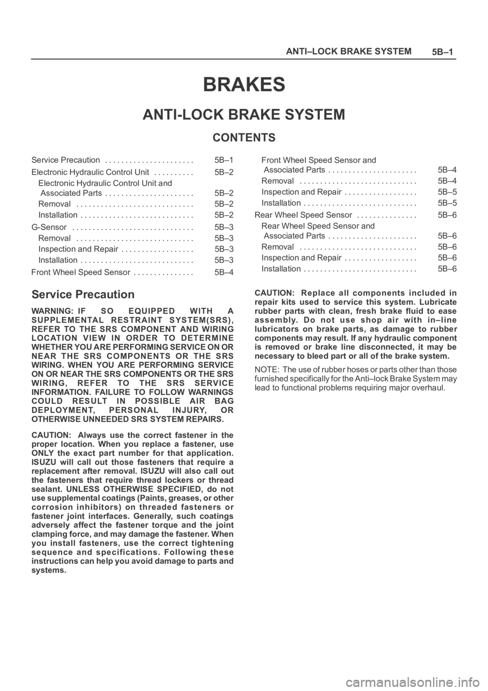
Service Precaution 5B–1. . . . . . . . . . . . . . . . . . . . . .
Electronic Hydraulic Control Unit 5B–2. . . . . . . . . .
Electronic Hydraulic Control Unit and
Associated Parts 5B–2. . . . . . . . . . . . . . . . . . . . . .
Removal 5B–2. . . . . . . . . . . . . . . . . . . . . . . . . . . . .
Installation 5B–2. . . . . . . . . . . . . . . . . . . . . . . . . . . .
G-Sensor 5B–3. . . . . . . . . . . . . . . . . . . . . . . . . . . . . .
Removal 5B–3. . . . . . . . . . . . . . . . . . . . . . . . . . . . .
Inspection and Repair 5B–3. . . . . . . . . . . . . . . . . .
Installation 5B–3. . . . . . . . . . . . . . . . . . . . . . . . . . . .
Front Wheel Speed Sensor 5B–4. . . . . . . . . . . . . . . Front Wheel Speed Sensor and
Associated Parts 5B–4. . . . . . . . . . . . . . . . . . . . . .
Removal 5B–4. . . . . . . . . . . . . . . . . . . . . . . . . . . . .
Inspection and Repair 5B–5. . . . . . . . . . . . . . . . . .
Installation 5B–5. . . . . . . . . . . . . . . . . . . . . . . . . . . .
Rear Wheel Speed Sensor 5B–6. . . . . . . . . . . . . . .
Rear Wheel Speed Sensor and
Associated Parts 5B–6. . . . . . . . . . . . . . . . . . . . . .
Removal 5B–6. . . . . . . . . . . . . . . . . . . . . . . . . . . . .
Inspection and Repair 5B–6. . . . . . . . . . . . . . . . . .
Installation 5B–6. . . . . . . . . . . . . . . . . . . . . . . . . . . .
Service Precaution
WARNING: IF SO EQUIPPED WITH A
SUPPLEMENTAL RESTRAINT SYSTEM(SRS),
REFER TO THE SRS COMPONENT AND WIRING
LOCATION VIEW IN ORDER TO DETERMINE
WHETHER YOU ARE PERFORMING SERVICE ON OR
NEAR THE SRS COMPONENTS OR THE SRS
WIRING. WHEN YOU ARE PERFORMING SERVICE
ON OR NEAR THE SRS COMPONENTS OR THE SRS
WIRING, REFER TO THE SRS SERVICE
INFORMATION. FAILURE TO FOLLOW WARNINGS
COULD RESULT IN POSSIBLE AIR BAG
DEPLOYMENT, PERSONAL INJURY, OR
OTHERWISE UNNEEDED SRS SYSTEM REPAIRS.
CAUTION: Always use the correct fastener in the
proper location. When you replace a fastener, use
ONLY the exact part number for that application.
ISUZU will call out those fasteners that require a
replacement after removal. ISUZU will also call out
the fasteners that require thread lockers or thread
sealant. UNLESS OTHERWISE SPECIFIED, do not
use supplemental coatings (Paints, greases, or other
corrosion inhibitors) on threaded fasteners or
fastener joint interfaces. Generally, such coatings
adversely affect the fastener torque and the joint
clamping force, and may damage the fastener. When
you install fasteners, use the correct tightening
sequence and specifications. Following these
instructions can help you avoid damage to parts and
systems.CAUTION: Replace all components included in
repair kits used to service this system. Lubricate
rubber parts with clean, fresh brake fluid to ease
assembly. Do not use shop air with in–line
lubricators on brake parts, as damage to rubber
components may result. If any hydraulic component
is removed or brake line disconnected, it may be
necessary to bleed part or all of the brake system.
NOTE: The use of rubber hoses or parts other than those
furnished specifically for the Anti–lock Brake System may
lead to functional problems requiring major overhaul.
5B–3 ANTI–LOCK BRAKE SYSTEM
G-Sensor
Removal
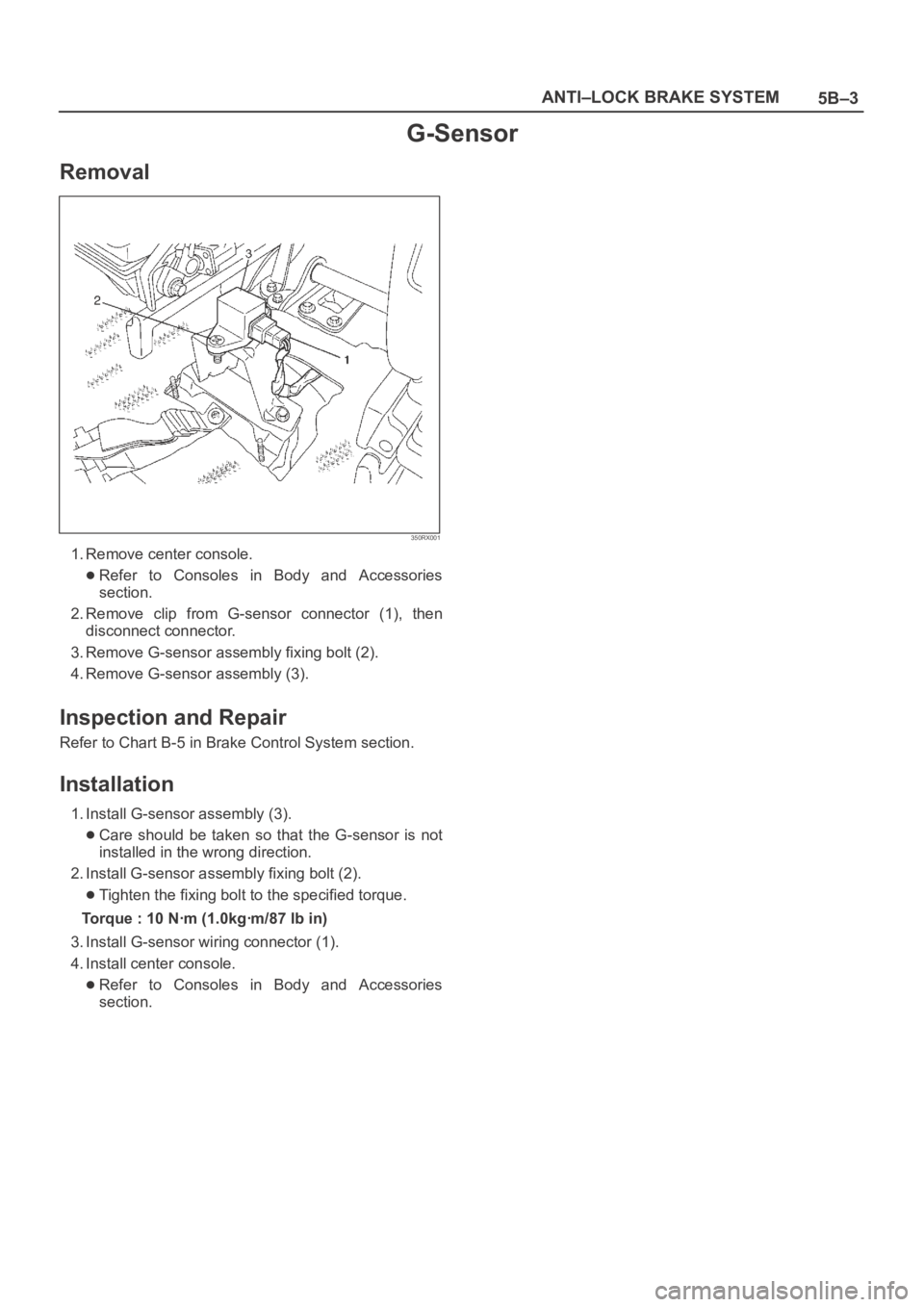
350RX001
1. Remove center console.
Refer to Consoles in Body and Accessories
section.
2. Remove clip from G-sensor connector (1), then
disconnect connector.
3. Remove G-sensor assembly fixing bolt (2).
4. Remove G-sensor assembly (3).
Inspection and Repair
Refer to Chart B-5 in Brake Control System section.
Installation
1. Install G-sensor assembly (3).
Care should be taken so that the G-sensor is not
installed in the wrong direction.
2. Install G-sensor assembly fixing bolt (2).
Tighten the fixing bolt to the specified torque.
Torque : 10 Nꞏm (1.0kgꞏm/87 lb in)
3. Install G-sensor wiring connector (1).
4. Install center console.
Refer to Consoles in Body and Accessories
section.