Page 4917 of 6000
6E–260
ENGINE DRIVEABILITY AND EMISSIONS
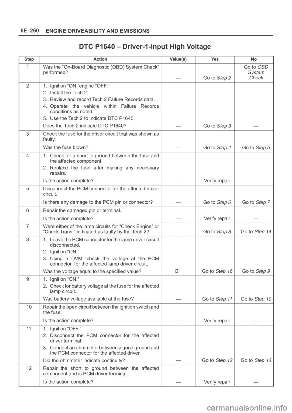
DTC P1640 – Driver-1-Input High Voltage
StepActionVa l u e ( s )Ye sNo
1Was the “On-Board Diagnostic (OBD) System Check”
performed?
—Go to Step 2
Go to OBD
System
Check
21. Ignition “ON,”engine “OFF.”
2. Install the Tech 2.
3. Review and record Tech 2 Failure Records data.
4. Operate the vehicle within Failure Records
conditions as noted.
5. Use the Tech 2 to indicate DTC P1640.
Does the Tech 2 indicate DTC P1640?
—Go to Step 3—
3Check the fuse for the driver circuit that was shown as
faulty.
Was the fuse blown?
—Go to Step 4Go to Step 5
41. Check for a short to ground between the fuse and
the affected component.
2. Replace the fuse after making any necessary
repairs.
Is the action complete?
—Verify repair—
5Disconnect the PCM connector for the affected driver
circuit.
Is there any damage to the PCM pin or connector?
—Go to Step 6Go to Step 7
6Repair the damaged pin or terminal.
Is the action complete?
—Verify repair—
7Were either of the lamp circuits for “Check Engine” or
“Check Trans.” indicated as faulty by the Tech 2?
—Go to Step 8Go to Step 14
81. Leave the PCM connector for the lamp driver circuit
disconnected.
2. Ignition “ON.”
3. Using a DVM, check the voltage at the PCM
connector for the affected lamp driver circuit.
Was the voltage equal to the specified value?
B+Go to Step 16Go to Step 9
91. Ignition “ON.”
2. Check for battery voltage at the fuse for the affected
lamp circuit.
Was battery voltage available at the fuse?
—Go to Step 11Go to Step 10
10Repair the open circuit between the ignition switch and
the fuse.
Is the action complete?
—Verify repair—
111. Ignition “OFF.”
2. Disconnect the PCM connector for the affected
driver terminal.
3. Connect an ohmmeter between a good ground and
the PCM connector for the affected driver.
Did the ohmmeter indicate continuity?
—Go to Step 12Go to Step 13
12Repair the short to ground between the affected
component and is PCM driver terminal.
Is the action complete?
—Verify repair—
Page 4918 of 6000
6E–261 ENGINE DRIVEABILITY AND EMISSIONS
DTC P1640 – Driver-1-Input High Voltage
StepNo Ye s Va l u e ( s ) Action
13Repair the open circuit between the fuse and the PCM
driver terminal for the affected circuit.
Is the action complete?
—Verify repair—
141. Connect the PCM.
2. Start the engine and let it idle.
3. Backprobe the affected terminal at the PCM with a
DVM.
Was the voltage equal to the specified value?
+BGo to Step 16Go to Step 15
151. Run the engine at idle.
2. Check for battery voltage at the fuse for the affected
circuit.
Was battery voltage available at the fuse?
—Go to Step 11Go to Step 10
16Replace the PCM.
IMPORTANT:The replacement PCM must be
programmed. Refer to
UBS 98model year Immobilizer
Workshop Manual.
Is the action complete?—Verify repair—
Page 4948 of 6000
6E–291 ENGINE DRIVEABILITY AND EMISSIONS
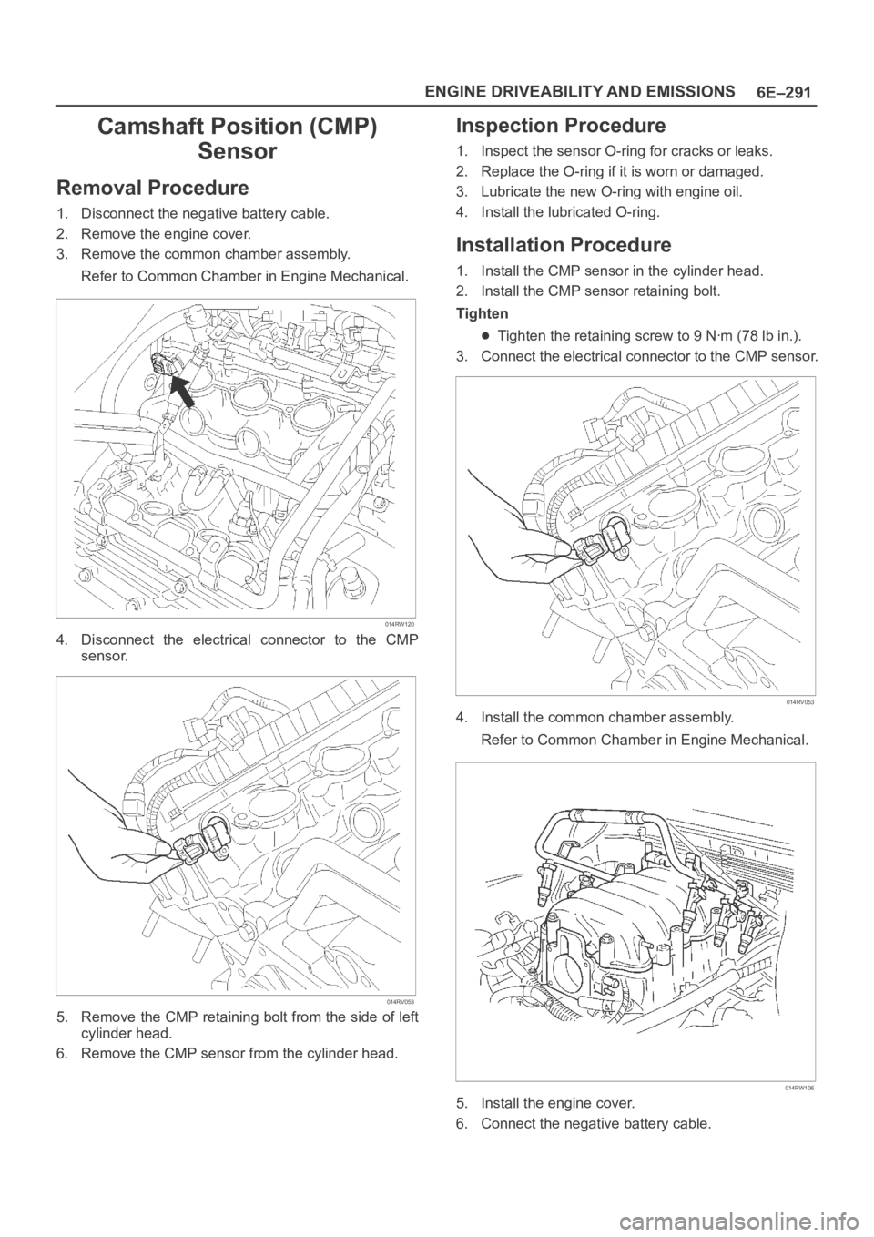
Camshaft Position (CMP)
Sensor
Removal Procedure
1. Disconnect the negative battery cable.
2. Remove the engine cover.
3. Remove the common chamber assembly.
Refer to Common Chamber in Engine Mechanical.
014RW120
4. Disconnect the electrical connector to the CMP
sensor.
014RV053
5. Remove the CMP retaining bolt from the side of left
cylinder head.
6. Remove the CMP sensor from the cylinder head.
Inspection Procedure
1. Inspect the sensor O-ring for cracks or leaks.
2. Replace the O-ring if it is worn or damaged.
3. Lubricate the new O-ring with engine oil.
4. Install the lubricated O-ring.
Installation Procedure
1. Install the CMP sensor in the cylinder head.
2. Install the CMP sensor retaining bolt.
Tighten
Tighten the retaining screw to 9 Nꞏm (78 lb in.).
3. Connect the electrical connector to the CMP sensor.
014RV053
4. Install the common chamber assembly.
Refer to Common Chamber in Engine Mechanical.
014RW106
5. Install the engine cover.
6. Connect the negative battery cable.
Page 4949 of 6000
6E–292
ENGINE DRIVEABILITY AND EMISSIONS
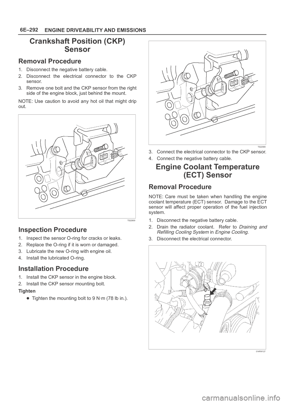
Crankshaft Position (CKP)
Sensor
Removal Procedure
1. Disconnect the negative battery cable.
2. Disconnect the electrical connector to the CKP
sensor.
3. Remove one bolt and the CKP sensor from the right
side of the engine block, just behind the mount.
NOTE: Use caution to avoid any hot oil that might drip
out.
TS22909
Inspection Procedure
1. Inspect the sensor O-ring for cracks or leaks.
2. Replace the O-ring if it is worn or damaged.
3. Lubricate the new O-ring with engine oil.
4. Install the lubricated O-ring.
Installation Procedure
1. Install the CKP sensor in the engine block.
2. Install the CKP sensor mounting bolt.
Tighten
Tighten the mounting bolt to 9 Nꞏm (78 lb in.).
TS22909
3. Connect the electrical connector to the CKP sensor.
4. Connect the negative battery cable.
Engine Coolant Temperature
(ECT) Sensor
Removal Procedure
NOTE: Care must be taken when handling the engine
coolant temperature (ECT) sensor. Damage to the ECT
sensor will affect proper operation of the fuel injection
system.
1. Disconnect the negative battery cable.
2. Drain the radiator coolant. Refer to
Draining and
Refilling Cooling System
in Engine Cooling.
3. Disconnect the electrical connector.
014RW127
Page 4950 of 6000
6E–293 ENGINE DRIVEABILITY AND EMISSIONS
4. Remove the ECT sensor from the coolant crossover.
014RW086
Installation Procedure
1. Apply sealer or the equivalent to the threads of the
ECT sensor.
2. Install the ECT sensor in the coolant crossover.
Tighten
Tighten the ECT sensor to 30 Nꞏm (22 lb ft.).
014RW086
3. Connect the electrical connector.
014RW085
4. Fill the radiator with coolant. Refer to Draining and
Refilling Cooling System
in Engine Cooling.
5. Connect the negative battery cable.
Heated Oxygen Sensor (HO2S)
Removal Procedure
1. Disconnect the negative battery cable.
2. Locate the oxygen sensors.
Bank 1 sensor 1 is mounted on the right-hand front
exhaust pipe.
TS22912
Page 4952 of 6000
6E–295 ENGINE DRIVEABILITY AND EMISSIONS
Installation Procedure
IMPORTANT:
A special anti-seize compound, P/N 5613695, is used
on the HO2S threads. This compound consists of
glass beads suspended in a liquid graphite solution.
The graphite burns away with engine heat, but the
glass beads will remain, making the sensor easier to
remove.
New or service sensors will already have the
compound applied to the threads. If a sensor is
removed and is to be reinstalled for any reason, the
threads must have anti-seize compound applied.
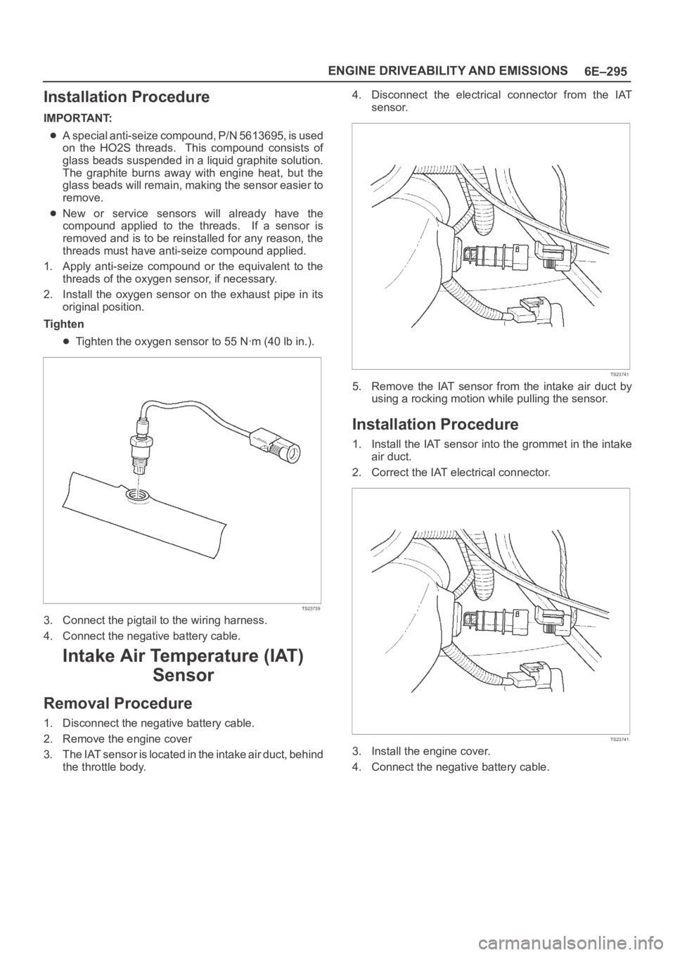
1. Apply anti-seize compound or the equivalent to the
threads of the oxygen sensor, if necessary.
2. Install the oxygen sensor on the exhaust pipe in its
original position.
Tighten
Tighten the oxygen sensor to 55 Nꞏm (40 lb in.).
TS23739
3. Connect the pigtail to the wiring harness.
4. Connect the negative battery cable.
Intake Air Temperature (IAT)
Sensor
Removal Procedure
1. Disconnect the negative battery cable.
2. Remove the engine cover
3. The IAT sensor is located in the intake air duct, behind
the throttle body.4. Disconnect the electrical connector from the IAT
sensor.
TS23741
5. Remove the IAT sensor from the intake air duct by
using a rocking motion while pulling the sensor.
Installation Procedure
1. Install the IAT sensor into the grommet in the intake
air duct.
2. Correct the IAT electrical connector.
TS23741
3. Install the engine cover.
4. Connect the negative battery cable.
Page 4953 of 6000
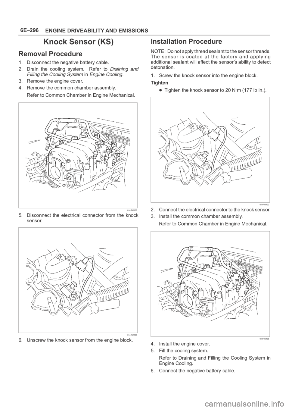
6E–296
ENGINE DRIVEABILITY AND EMISSIONS
Knock Sensor (KS)
Removal Procedure
1. Disconnect the negative battery cable.
2. Drain the cooling system. Refer to
Draining and
Filling the Cooling System
in Engine Cooling.
3. Remove the engine cover.
4. Remove the common chamber assembly.
Refer to Common Chamber in Engine Mechanical.
014RW106
5. Disconnect the electrical connector from the knock
sensor.
014RW103
6. Unscrew the knock sensor from the engine block.
Installation Procedure
NOTE: Do not apply thread sealant to the sensor threads.
The sensor is coated at the factory and applying
additional sealant will affect the sensor’s ability to detect
detonation.
1. Screw the knock sensor into the engine block.
Tighten
Tighten the knock sensor to 20 Nꞏm (177 lb in.).
014RW103
2. Connect the electrical connector to the knock sensor.
3. Install the common chamber assembly.
Refer to Common Chamber in Engine Mechanical.
014RW106
4. Install the engine cover.
5. Fill the cooling system.
Refer to Draining and Filling the Cooling System in
Engine Cooling.
6. Connect the negative battery cable.
Page 4954 of 6000
6E–297 ENGINE DRIVEABILITY AND EMISSIONS
Mass Air Flow (MAF) Sensor
Removal Procedure
1. Disconnect the negative battery cable.
2. Disconnect the electrical connector from the MAF
sensor.
TS23740
3. Loosen the clamps which secure the intake air duct
and the air cleaner to the MAF sensor.
4. Remove the intake air duct from the MAF sensor.
5. Remove the MAF sensor from the air cleaner.
TS23781
Installation Procedure
1. Install the MAF sensor on the air cleaner with the
clamp.2. Install the intake air duct and the clamp on the MAF
sensor.
TS23781
3. Tighten the clamps to secure the MAF sensor to the
intake air duct and the air cleaner.
4. Connect the MAF electrical connector.
5. Connect the negative battery cable.
Manifold Absolute Pressure
(MAP) Sensor
Removal Procedure
1. Disconnect the negative battery cable.
2. Disconnect the electrical connector from the MAP
sensor.
055RW005
3. Remove the bolt securing the MAP sensor to the
mounting bracket on the common chamber.