1998 OPEL FRONTERA battery
[x] Cancel search: batteryPage 4955 of 6000
6E–298
ENGINE DRIVEABILITY AND EMISSIONS
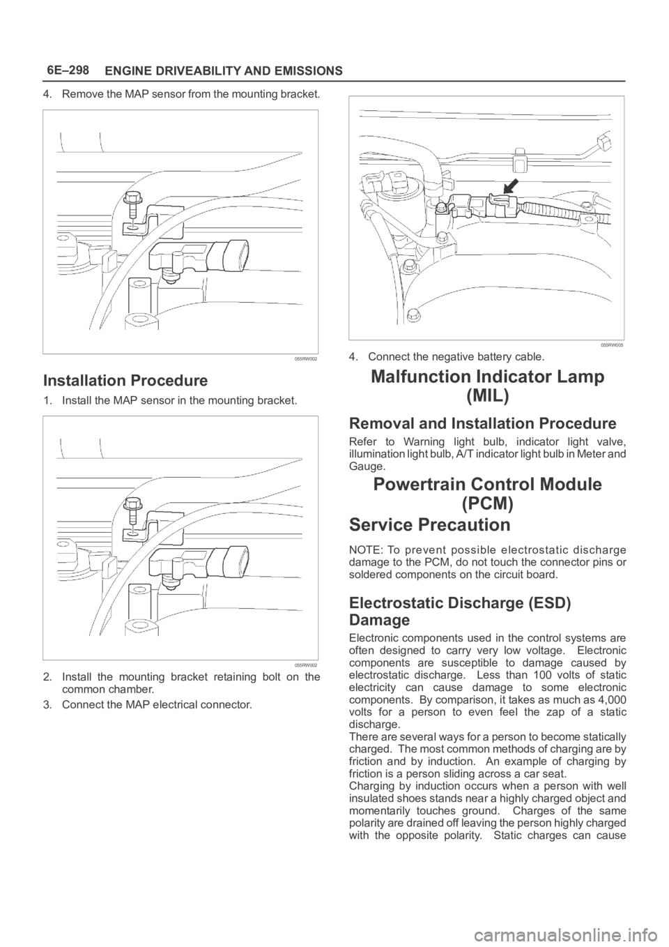
4. Remove the MAP sensor from the mounting bracket.
055RW002
Installation Procedure
1. Install the MAP sensor in the mounting bracket.
055RW002
2. Install the mounting bracket retaining bolt on the
common chamber.
3. Connect the MAP electrical connector.
055RW005
4. Connect the negative battery cable.
Malfunction Indicator Lamp
(MIL)
Removal and Installation Procedure
Refer to Warning light bulb, indicator light valve,
illumination light bulb, A/T indicator light bulb in Meter and
Gauge.
Powertrain Control Module
(PCM)
Service Precaution
NOTE: To prevent possible electrostatic discharge
damage to the PCM, do not touch the connector pins or
soldered components on the circuit board.
Electrostatic Discharge (ESD)
Damage
Electronic components used in the control systems are
often designed to carry very low voltage. Electronic
components are susceptible to damage caused by
electrostatic discharge. Less than 100 volts of static
electricity can cause damage to some electronic
components. By comparison, it takes as much as 4,000
volts for a person to even feel the zap of a static
discharge.
There are several ways for a person to become statically
charged. The most common methods of charging are by
friction and by induction. An example of charging by
friction is a person sliding across a car seat.
Charging by induction occurs when a person with well
insulated shoes stands near a highly charged object and
momentarily touches ground. Charges of the same
polarity are drained off leaving the person highly charged
with the opposite polarity. Static charges can cause
Page 4956 of 6000
6E–299 ENGINE DRIVEABILITY AND EMISSIONS
damage, therefore, it is important to use care when
handling and testing electronic components.
NOTE: To prevent possible Electrostatic Discharge
damage, follow these guidelines:
Do not touch the control module connector pins or
soldered components on the control module circuit
board.
Do not open the replacement part package until the
part is ready to be installed.
Before removing the part from the package, ground
the package to a known good ground on the vehicle.
If the part has been handled while sliding across the
seat, or while sitting down from a standing position, or
while walking a distance, touch a known good ground
before installing the part.
NOTE: To prevent internal PCM damage, the ignition
must be in the “OFF” position in order to disconnect or
reconnect power to the PCM (for example: battery cable,
PCM pigtail, PCM fuse, jumper cables, etc.).
IMPORTANT:When replacing the production PCM
with a service PCM, it is important to transfer the
broadcast code and production PCM number to the
service PCM label. This will allow positive identification of
PCM parts throughout the service life of the vehicle. Do
not record this information on the metal PCM cover.
IMPORTANT:The ignition should always be in the
“OFF” position in order to install or remove the PCM
connectors.
Service of the PCM should normally consist of either re-
placement of the PCM or EEPROM programming. If the
diagnostic procedures call for the PCM to be replaced,
the PCM should be checked first to ensure it is the correct
part. If it is, remove the faulty PCM and install the new
service PCM.
The service PCM EEPROM will not be programmed.
DTC P0601 indicates the check sum error.
Removal Procedure
1. Disconnect the negative battery cable.
2. Block the wheels.
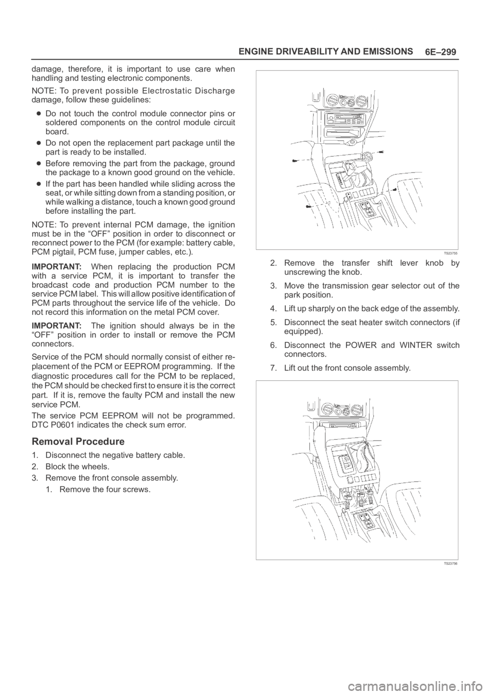
3. Remove the front console assembly.
1. Remove the four screws.
TS23755
2. Remove the transfer shift lever knob by
unscrewing the knob.
3. Move the transmission gear selector out of the
park position.
4. Lift up sharply on the back edge of the assembly.
5. Disconnect the seat heater switch connectors (if
equipped).
6. Disconnect the POWER and WINTER switch
connectors.
7. Lift out the front console assembly.
TS23756
Page 4957 of 6000
6E–300
ENGINE DRIVEABILITY AND EMISSIONS
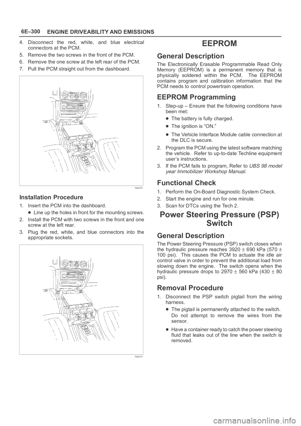
4. Disconnect the red, white, and blue electrical
connectors at the PCM.
5. Remove the two screws in the front of the PCM.
6. Remove the one screw at the left rear of the PCM.
7. Pull the PCM straight out from the dashboard.
TS23757
Installation Procedure
1. Insert the PCM into the dashboard.
Line up the holes in front for the mounting screws.
2. Install the PCM with two screws in the front and one
screw at the left rear.
3. Plug the red, white, and blue connectors into the
appropriate sockets.
TS23757
EEPROM
General Description
The Electronically Erasable Programmable Read Only
Memory (EEPROM) is a permanent memory that is
physically soldered within the PCM. The EEPROM
contains program and calibration information that the
PCM needs to control powertrain operation.
EEPROM Programming
1. Step-up – Ensure that the following conditions have
been met:
The battery is fully charged.
The ignition is “ON.”
The Vehicle Interface Module cable connection at
the DLC is secure.
2. Program the PCM using the latest software matching
the vehicle. Refer to up-to-date Techline equipment
user’s instructions.
3. If the PCM fails to program, Refer to
UBS 98 model
year Immobilizer Workshop Manual.
Functional Check
1. Perform the On-Board Diagnostic System Check.
2. Start the engine and run for one minute.
3. Scan for DTCs using the Tech 2.
Power Steering Pressure (PSP)
Switch
General Description
The Power Steering Pressure (PSP) switch closes when
the hydraulic pressure reaches 3920
690 kPa (570
100 psi). This causes the PCM to actuate the idle air
control valve in order to prevent the additional load from
slowing down the engine. The switch opens when the
hydraulic pressure drops to 2970
560 kPa (430 80
psi).
Removal Procedure
1. Disconnect the PSP switch pigtail from the wiring
harness.
The pigtail is permanently attached to the switch.
Do not attempt to remove the wires from the
sensor.
Have a container ready to catch the power steering
fluid that leaks out of the line when the switch is
removed.
Page 4958 of 6000
6E–301 ENGINE DRIVEABILITY AND EMISSIONS
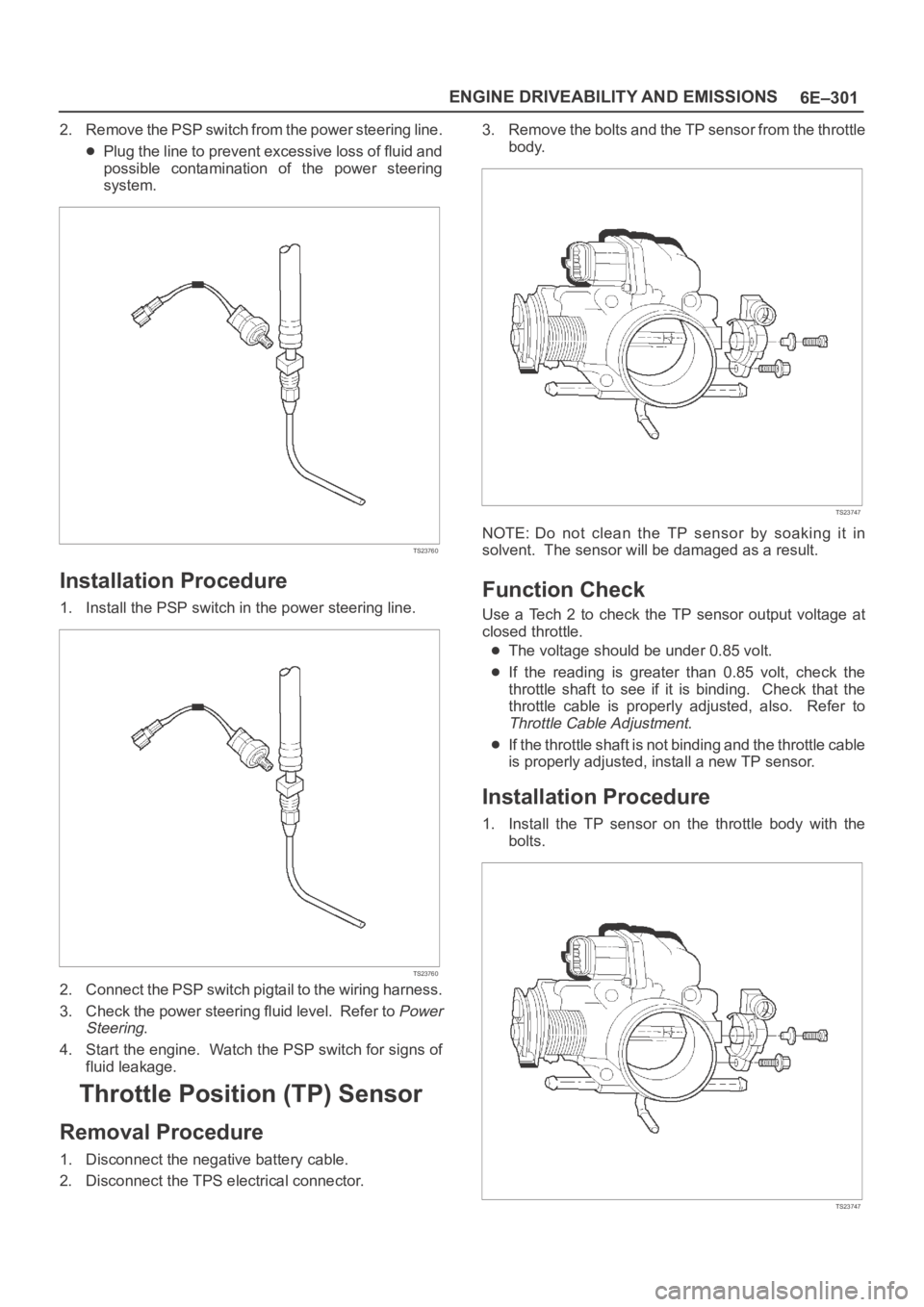
2. Remove the PSP switch from the power steering line.
Plug the line to prevent excessive loss of fluid and
possible contamination of the power steering
system.
TS23760
Installation Procedure
1. Install the PSP switch in the power steering line.
TS23760
2. Connect the PSP switch pigtail to the wiring harness.
3. Check the power steering fluid level. Refer to
Power
Steering
.
4. Start the engine. Watch the PSP switch for signs of
fluid leakage.
Throttle Position (TP) Sensor
Removal Procedure
1. Disconnect the negative battery cable.
2. Disconnect the TPS electrical connector.3. Remove the bolts and the TP sensor from the throttle
body.
TS23747
NOTE: Do not clean the TP sensor by soaking it in
solvent. The sensor will be damaged as a result.
Function Check
Use a Tech 2 to check the TP sensor output voltage at
closed throttle.
The voltage should be under 0.85 volt.
If the reading is greater than 0.85 volt, check the
throttle shaft to see if it is binding. Check that the
throttle cable is properly adjusted, also. Refer to
Throttle Cable Adjustment.
If the throttle shaft is not binding and the throttle cable
is properly adjusted, install a new TP sensor.
Installation Procedure
1. Install the TP sensor on the throttle body with the
bolts.
TS23747
Page 4959 of 6000
6E–302
ENGINE DRIVEABILITY AND EMISSIONS
2. Connect the TP electrical connector.
3. Install the negative battery cable.
Vehicle Speed Sensor (VSS)
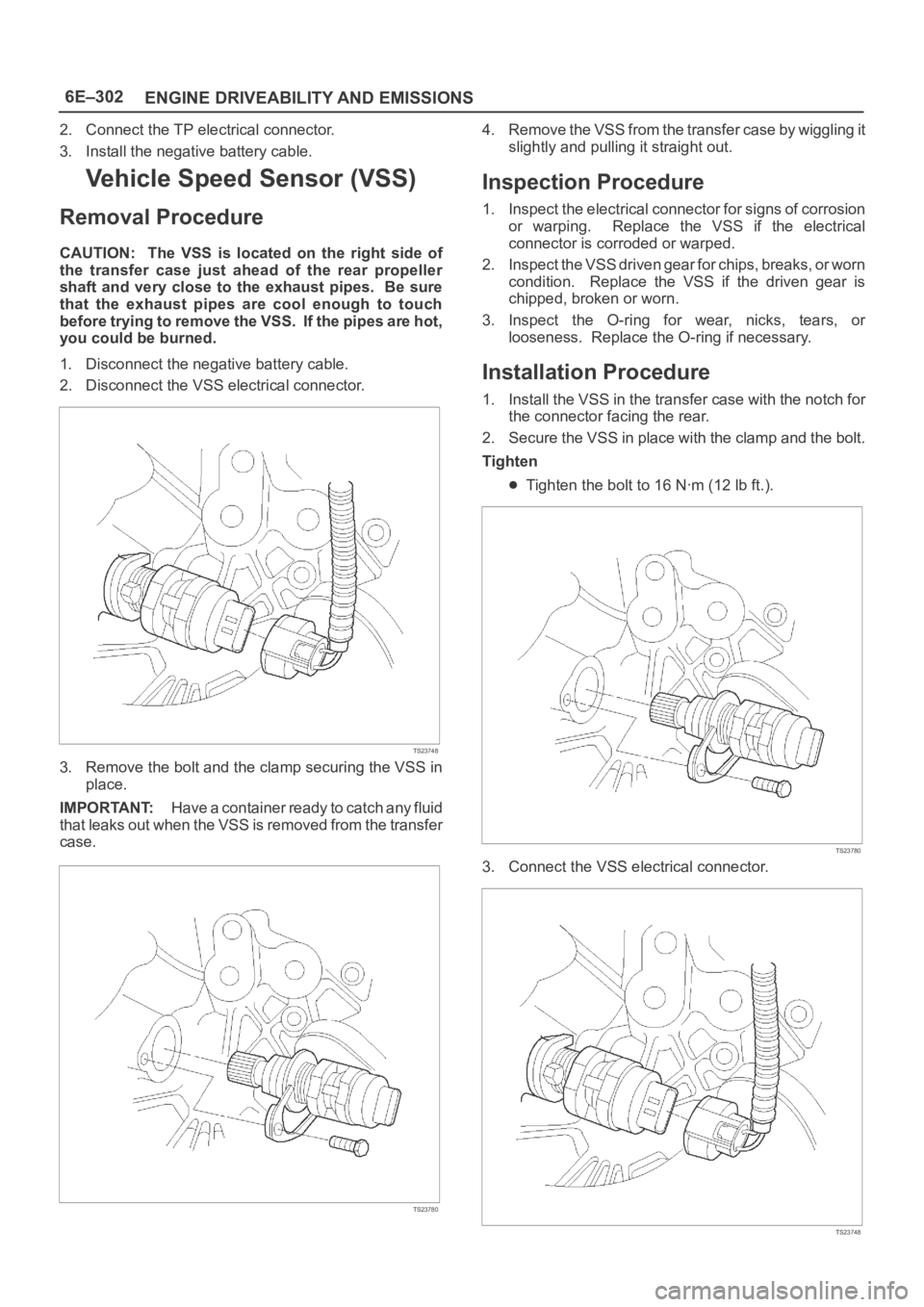
Removal Procedure
CAUTION: The VSS is located on the right side of
the transfer case just ahead of the rear propeller
shaft and very close to the exhaust pipes. Be sure
that the exhaust pipes are cool enough to touch
before trying to remove the VSS. If the pipes are hot,
you could be burned.
1. Disconnect the negative battery cable.
2. Disconnect the VSS electrical connector.
TS23748
3. Remove the bolt and the clamp securing the VSS in
place.
IMPORTANT:H a v e a c o n t a i n e r r e a d y t o c a t c h a n y f l u i d
that leaks out when the VSS is removed from the transfer
case.
TS23780
4. Remove the VSS from the transfer case by wiggling it
slightly and pulling it straight out.
Inspection Procedure
1. Inspect the electrical connector for signs of corrosion
or warping. Replace the VSS if the electrical
connector is corroded or warped.
2. Inspect the VSS driven gear for chips, breaks, or worn
condition. Replace the VSS if the driven gear is
chipped, broken or worn.
3. Inspect the O-ring for wear, nicks, tears, or
looseness. Replace the O-ring if necessary.
Installation Procedure
1. Install the VSS in the transfer case with the notch for
the connector facing the rear.
2. Secure the VSS in place with the clamp and the bolt.
Tighten
Tighten the bolt to 16 Nꞏm (12 lb ft.).
TS23780
3. Connect the VSS electrical connector.
TS23748
Page 4960 of 6000
6E–303 ENGINE DRIVEABILITY AND EMISSIONS
4. Check the transfer case oil level. Add fluid if
necessary.
5. Connect the negative battery cable.
Air Cleaner/Air Filter
Removal Procedure
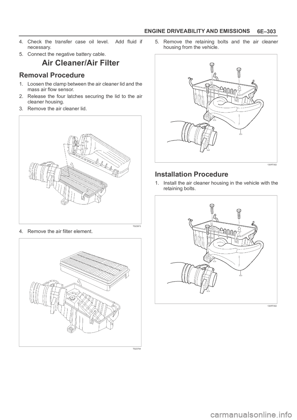
1. Loosen the clamp between the air cleaner lid and the
mass air flow sensor.
2. Release the four latches securing the lid to the air
cleaner housing.
3. Remove the air cleaner lid.
TS23973
4. Remove the air filter element.
TS23794
5. Remove the retaining bolts and the air cleaner
housing from the vehicle.
130RT002
Installation Procedure
1. Install the air cleaner housing in the vehicle with the
retaining bolts.
130RT002
Page 4961 of 6000
6E–304
ENGINE DRIVEABILITY AND EMISSIONS
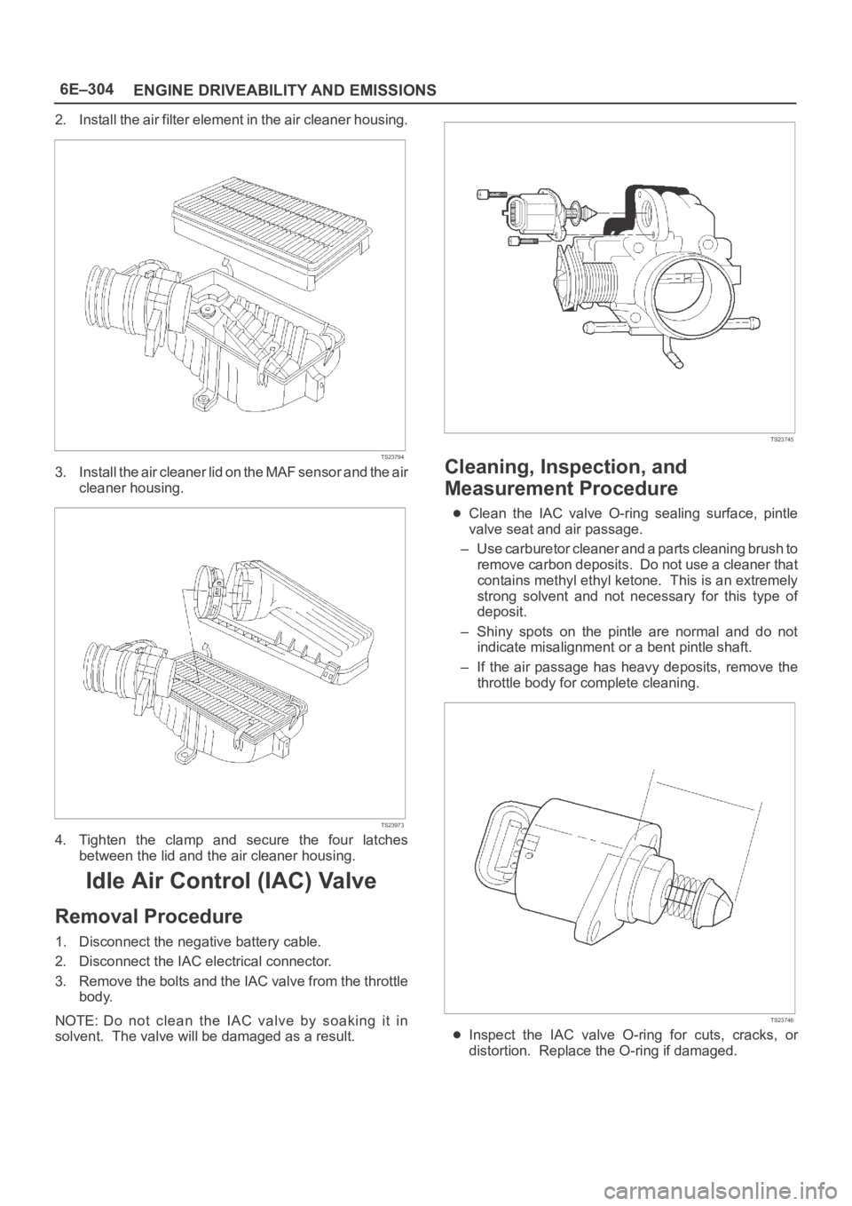
2. Install the air filter element in the air cleaner housing.
TS23794
3. Install the air cleaner lid on the MAF sensor and the air
cleaner housing.
TS23973
4. Tighten the clamp and secure the four latches
between the lid and the air cleaner housing.
Idle Air Control (IAC) Valve
Removal Procedure
1. Disconnect the negative battery cable.
2. Disconnect the IAC electrical connector.
3. Remove the bolts and the IAC valve from the throttle
body.
NOTE: Do not clean the IAC valve by soaking it in
solvent. The valve will be damaged as a result.
TS23745
Cleaning, Inspection, and
Measurement Procedure
Clean the IAC valve O-ring sealing surface, pintle
valve seat and air passage.
– Use carburetor cleaner and a parts cleaning brush to
remove carbon deposits. Do not use a cleaner that
contains methyl ethyl ketone. This is an extremely
strong solvent and not necessary for this type of
deposit.
– Shiny spots on the pintle are normal and do not
indicate misalignment or a bent pintle shaft.
– If the air passage has heavy deposits, remove the
throttle body for complete cleaning.
TS23746
Inspect the IAC valve O-ring for cuts, cracks, or
distortion. Replace the O-ring if damaged.
Page 4962 of 6000
6E–305 ENGINE DRIVEABILITY AND EMISSIONS
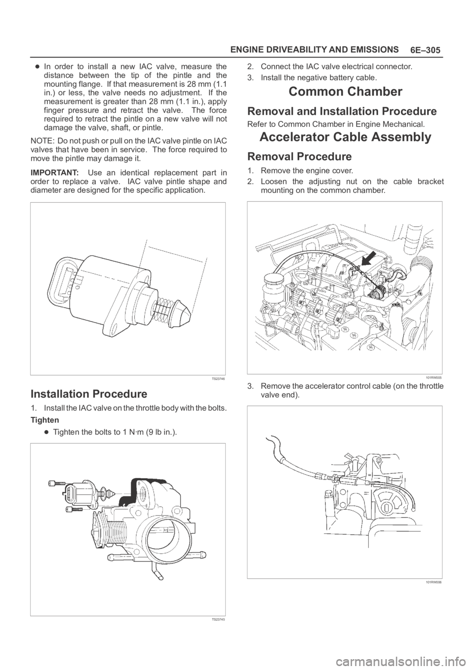
In order to install a new IAC valve, measure the
distance between the tip of the pintle and the
mounting flange. If that measurement is 28 mm (1.1
in.) or less, the valve needs no adjustment. If the
measurement is greater than 28 mm (1.1 in.), apply
finger pressure and retract the valve. The force
required to retract the pintle on a new valve will not
damage the valve, shaft, or pintle.
NOTE: Do not push or pull on the IAC valve pintle on IAC
valves that have been in service. The force required to
move the pintle may damage it.
IMPORTANT:Use an identical replacement part in
order to replace a valve. IAC valve pintle shape and
diameter are designed for the specific application.
TS23746
Installation Procedure
1. Install the IAC valve on the throttle body with the bolts.
Tighten
Tighten the bolts to 1 Nꞏm (9 lb in.).
TS23745
2. Connect the IAC valve electrical connector.
3. Install the negative battery cable.
Common Chamber
Removal and Installation Procedure
Refer to Common Chamber in Engine Mechanical.
Accelerator Cable Assembly
Removal Procedure
1. Remove the engine cover.
2. Loosen the adjusting nut on the cable bracket
mounting on the common chamber.
101RW005
3. Remove the accelerator control cable (on the throttle
valve end).
101RW006