Page 5016 of 6000
6F–5 ENGINE EXHAUST
Three Way Catalytic Converter
Removal
1. Disconnect battery ground cable.
2. Raise the vehicle and support with suitable safety
stands.
3. Remove three way exhaust pipe fixing bolts and nuts.
150RW065
Installation
1. Install three way catalytic converter between three
way exhaust pipe and silencer.
2. Tighten nuts to the specified torque.
Torque
Nuts : 43 Nꞏm (4.4 Kgꞏm/32 lb ft)
Page 5017 of 6000

6F–6ENGINE EXHAUST
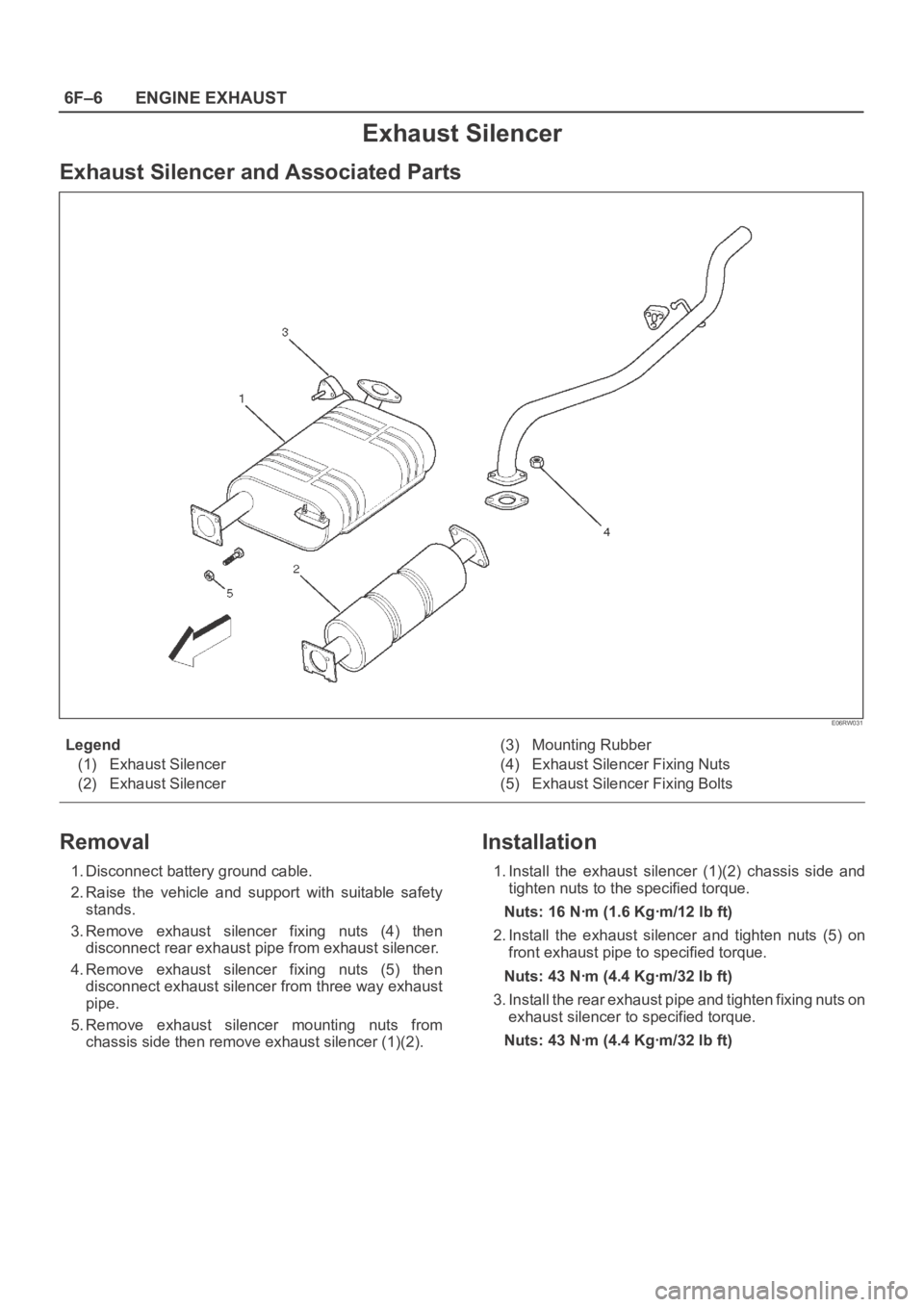
Exhaust Silencer
Exhaust Silencer and Associated Parts
E06RW031
Legend
(1) Exhaust Silencer
(2) Exhaust Silencer(3) Mounting Rubber
(4) Exhaust Silencer Fixing Nuts
(5) Exhaust Silencer Fixing Bolts
Removal
1. Disconnect battery ground cable.
2. Raise the vehicle and support with suitable safety
stands.
3. Remove exhaust silencer fixing nuts (4) then
disconnect rear exhaust pipe from exhaust silencer.
4. Remove exhaust silencer fixing nuts (5) then
disconnect exhaust silencer from three way exhaust
pipe.
5. Remove exhaust silencer mounting nuts from
chassis side then remove exhaust silencer (1)(2).
Installation
1. Install the exhaust silencer (1)(2) chassis side and
tighten nuts to the specified torque.
Nuts: 16 Nꞏm (1.6 Kgꞏm/12 lb ft)
2. Install the exhaust silencer and tighten nuts (5) on
front exhaust pipe to specified torque.
Nuts: 43 Nꞏm (4.4 Kgꞏm/32 lb ft)
3. Install the rear exhaust pipe and tighten fixing nuts on
exhaust silencer to specified torque.
Nuts: 43 Nꞏm (4.4 Kgꞏm/32 lb ft)
Page 5018 of 6000
6F–7 ENGINE EXHAUST
Rear Exhaust pipe
Rear Exhaust pipe and Associated Parts
E06RW033
Legend
(1) Mounting Rubber(2) Rear Exhaust Pipe
(3) Rear Exhaust Pipe Fixing Nuts
Removal
1. Disconnect battery ground cable.
2. Raise the vehicle and support with suitable safety
stands.
3. Remove rear exhaust pipe fixing nuts (3), then
disconnect rear exhaust pipe from exhaust silencer.
4. Remove mounting rubber (1).
5. Remove rear exhaust pipe (2).
Installation
1. Install the mounting rubber (1).
2. Install the exhaust pipe (2) and tighten two nuts (3) on
exhaust silencer to specified torque.
Nuts: 43 Nꞏm (4.4 Kgꞏm/32 lb ft)
Page 5026 of 6000

6G–7 ENGINE LUBRICATION
Oil Pan and Crankcase
Removal
1. Disconnect battery ground cable.
2. Drain engine oil.
3. Lift vehicle by supporting the frame.
4. Remove front wheels.
5. Remove oil level dipstick from level gauge tube.
6. Remove stone guard.
7. Remove radiator under fan shroud.
8. Remove suspension cross member fixing bolts, 2 pcs
each per side and remove suspension cross member.
9. Remove pitman arm and relay lever assembly, using
the 5–8840–2005–0 remover, remove pitman arm
from the steering unit and remove four fixing bolts for
relay lever assembly.
10. Remove axle housing assembly four fixing bolts from
housing isolator side and mounting bolts from wheel
side. At this time support the axle with a garage jack
and remove axle housing assembly.
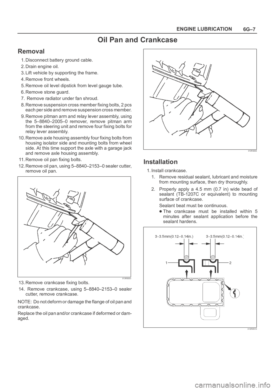
11. Remove oil pan fixing bolts.
12. Remove oil pan, using 5–8840–2153–0 sealer cutter,
remove oil pan.
013RS003
13. Remove crankcase fixing bolts.
14. Remove crankcase, using 5–8840–2153–0 sealer
cutter, remove crankcase.
NOTE: Do not deform or damage the flange of oil pan and
crankcase.
Replace the oil pan and/or crankcase if deformed or dam-
aged.
013RS003
Installation
1. Install crankcase.
1. Remove residual sealant, lubricant and moisture
from mounting surface, then dry thoroughly.
2. Properly apply a 4.5 mm (0.7 in) wide bead of
sealant (TB-1207C or equivalent) to mounting
surface of crankcase.
Sealant beat must be continuous.
The crankcase must be installed within 5
minutes after sealant application before the
sealant hardens.
013RW010
Page 5029 of 6000

6G–10
ENGINE LUBRICATION
Oil Pump
Removal
1. Disconnect battery ground cable.
2. Drain engine oil.
3. Remove crankcase assembly.
Refer to removal procedure for Oil Pan and
Crankcase in this manual.
4. Remove crankshaft pulley.
Refer to removal procedure for Crankshaft Pulley in
this manual.
5. Remove timing belt.
Refer to removal procedure for Timing Belt in this
manual.
6. Remove timing pulley from crankshaft.
7. Remove four fixing bolts from oil filter assembly.
8. Remove oil strainer fixing bolts, remove oil strainer
assembly with O-ring.
9. Remove three bolts from oil pipe and O-ring.
10. Remove eight oil pump fixing bolts, then oil pump
assembly.
11. Remove sealant from mounting surface of oil pump
assembly, cylinder block and take care not to damage
mounting surfaces of oil pump and cylinder block.
Installation
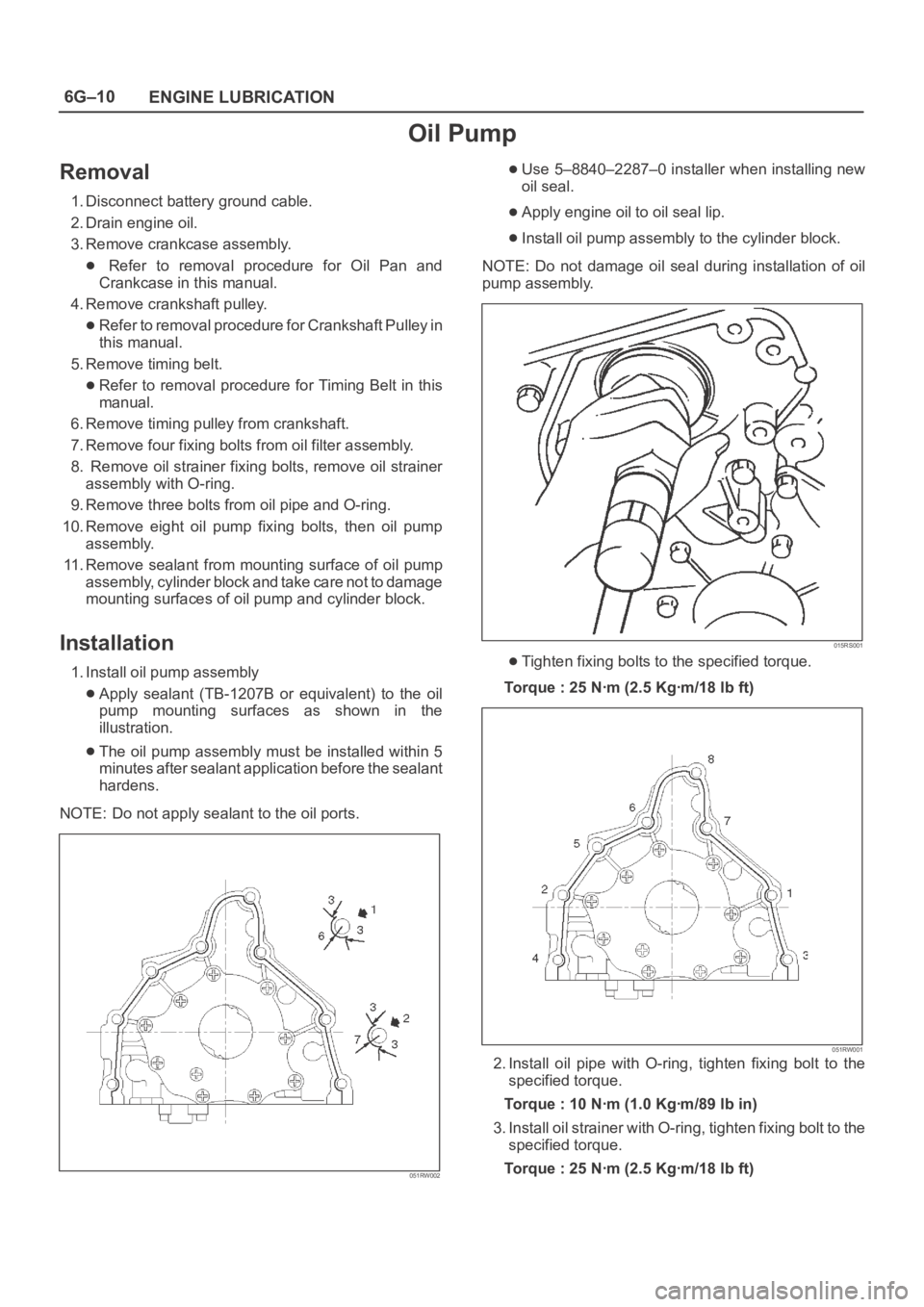
1. Install oil pump assembly
Apply sealant (TB-1207B or equivalent) to the oil
pump mounting surfaces as shown in the
illustration.
The oil pump assembly must be installed within 5
minutes after sealant application before the sealant
hardens.
NOTE: Do not apply sealant to the oil ports.
051RW002
Use 5–8840–2287–0 installer when installing new
oil seal.
Apply engine oil to oil seal lip.
Install oil pump assembly to the cylinder block.
NOTE: Do not damage oil seal during installation of oil
pump assembly.
015RS001
Tighten fixing bolts to the specified torque.
Torque : 25 Nꞏm (2.5 Kgꞏm/18 lb ft)
051RW001
2. Install oil pipe with O-ring, tighten fixing bolt to the
specified torque.
Torque : 10 Nꞏm (1.0 Kgꞏm/89 lb in)
3. Install oil strainer with O-ring, tighten fixing bolt to the
specified torque.
Torque : 25 Nꞏm (2.5 Kgꞏm/18 lb ft)
Page 5031 of 6000
6G–12
ENGINE LUBRICATION
Oil Pump Oil Seal
Removal
1. Disconnect battery ground cable.
2. Drain engine oil.
3. Remove crankshaft pulley.
Refer to removal procedure for Crankshaft Pulley in
this manual.
4. Remove timing belt.
Refer to removal procedure for Timing Belt in this
manual.
5. Remove timing pulley from crankshaft.
6. Remove oil pump oil seal using a sealer puller.
NOTE: Take care not to damage sealing surfaces of oil
pump and crankshaft when removing oil seal.
Installation
1. Install oil pump oil seal, apply engine oil to oil seal lip,
then install oil seal using 5–8840–2287–0 installer.
015RS001
2. Install timing pulley to crankshaft.
3. Install timing belt.
Refer to installation procedure for Timing Belt in this
manual.
4. Install crankshaft pulley.
Refer to installation procedure for Crankshaft
Pulley in this manual.
5. Refill engine oil until full level.
Page 5032 of 6000
6G–13 ENGINE LUBRICATION
Oil Filter
Removal
1. Disconnect battery ground cable.
2. Drain engine oil.
3. Remove oil filter using 5-8840-0203-0 filter wrench.
Installation
1. Clean filter fitting surface and apply small amount of
engine oil to sealing surface.
2. Install oil filter cartridge by hand until it comes in
contact with sealing surface then rotate additional 2/3
turn to tighten using 5-8840-0203-0 filter wrench.
050RW001
Legend
(1) Oil Pump
(2) Oil Filter
(3) Oil Gallery
(4) From Filter
(5) To Filter
3. Fill engine oil until full level on dipstick.
4. Reconnect battery ground cable.
Page 5299 of 6000

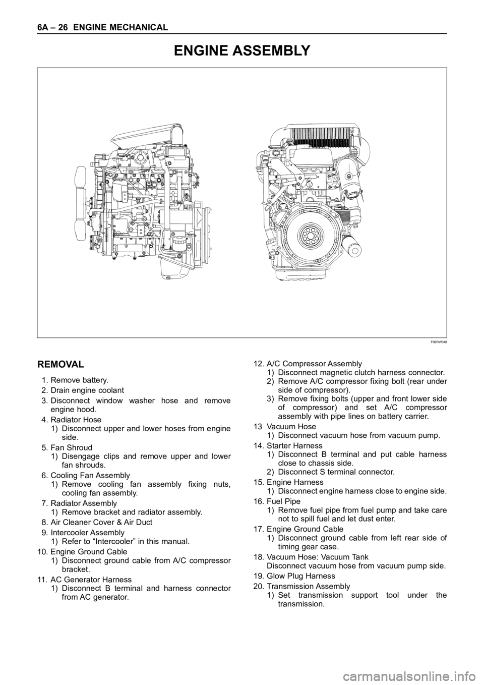
6A – 26 ENGINE MECHANICAL
ENGINE ASSEMBLY
F06RW048
REMOVAL
1. Remove battery.
2. Drain engine coolant
3. Disconnect window washer hose and remove
engine hood.
4. Radiator Hose
1) Disconnect upper and lower hoses from engine
side.
5. Fan Shroud
1) Disengage clips and remove upper and lower
fan shrouds.
6. Cooling Fan Assembly
1) Remove cooling fan assembly fixing nuts,
cooling fan assembly.
7. Radiator Assembly
1) Remove bracket and radiator assembly.
8. Air Cleaner Cover & Air Duct
9. Intercooler Assembly
1) Refer to “Intercooler” in this manual.
10. Engine Ground Cable
1) Disconnect ground cable from A/C compressor
bracket.
11. AC Generator Harness
1) Disconnect B terminal and harness connector
from AC generator.12. A/C Compressor Assembly
1) Disconnect magnetic clutch harness connector.
2) Remove A/C compressor fixing bolt (rear under
side of compressor).
3) Remove fixing bolts (upper and front lower side
of compressor) and set A/C compressor
assembly with pipe lines on battery carrier.
13 Vacuum Hose
1) Disconnect vacuum hose from vacuum pump.
14. Starter Harness
1) Disconnect B terminal and put cable harness
close to chassis side.
2) Disconnect S terminal connector.
15. Engine Harness
1) Disconnect engine harness close to engine side.
16. Fuel Pipe
1) Remove fuel pipe from fuel pump and take care
not to spill fuel and let dust enter.
17. Engine Ground Cable
1) Disconnect ground cable from left rear side of
timing gear case.
18. Vacuum Hose: Vacuum Tank
Disconnect vacuum hose from vacuum pump side.
19. Glow Plug Harness
20. Transmission Assembly
1) Set transmission support tool under the
transmission.