Page 5638 of 6000

6E–209 4JX1–TC ENGINE DRIVEABILITY AND EMISSIONS
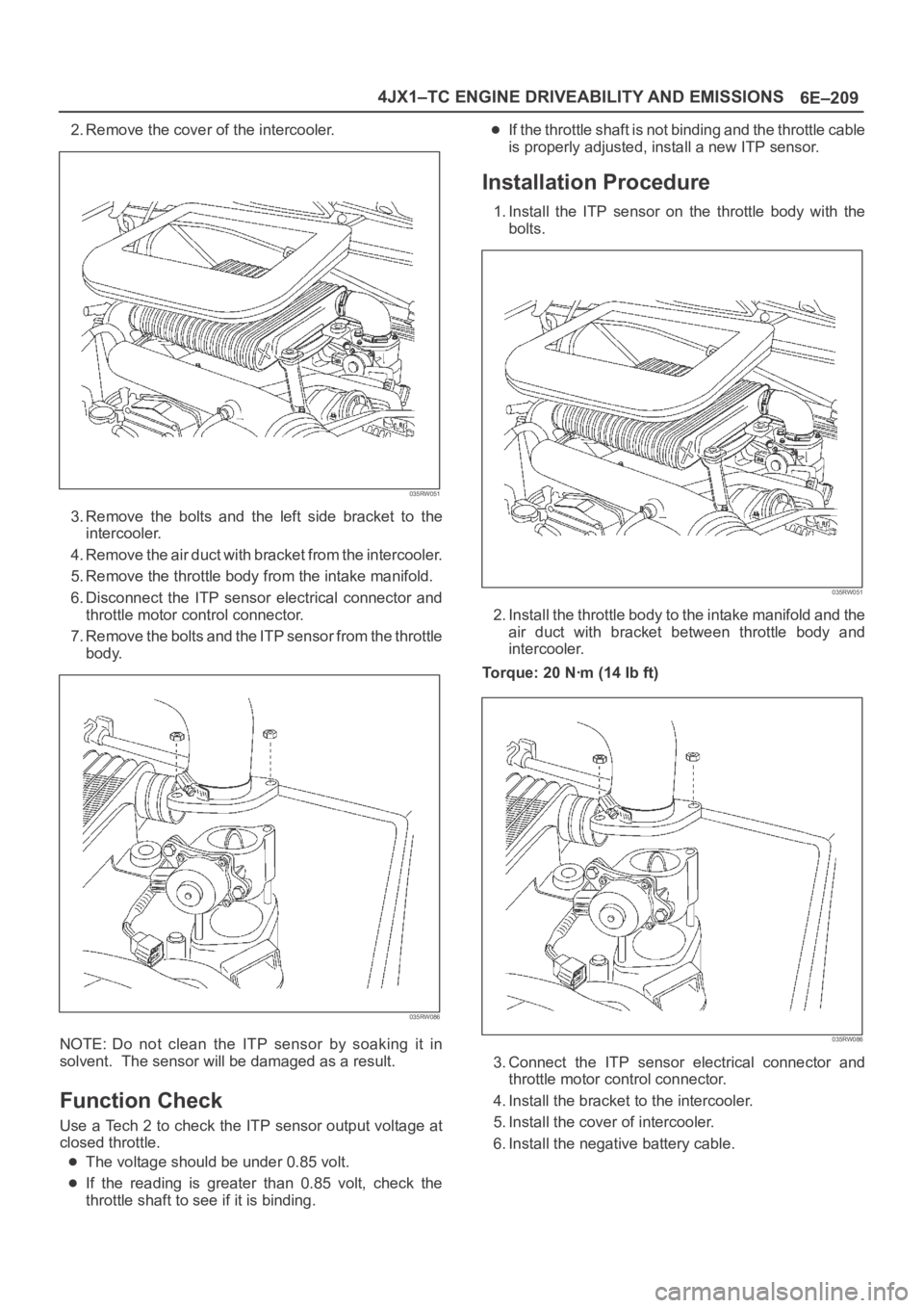
2. Remove the cover of the intercooler.
035RW051
3. Remove the bolts and the left side bracket to the
intercooler.
4 . R e m o v e t h e a i r d u c t w i t h b r a c k e t f r o m t h e i n t e r c o o l e r.
5. Remove the throttle body from the intake manifold.
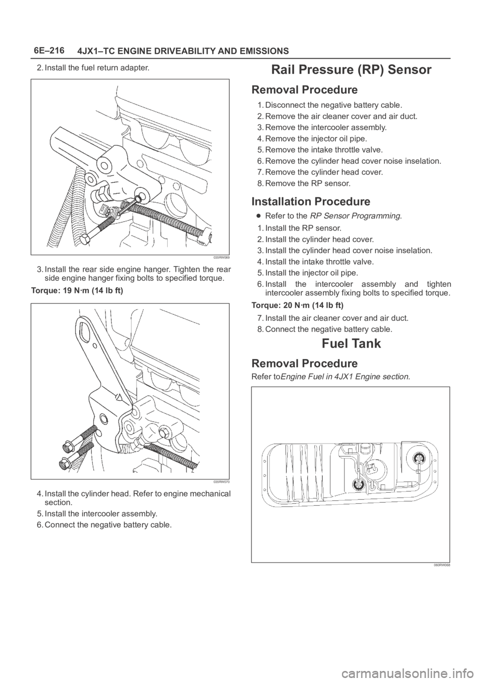
6. Disconnect the ITP sensor electrical connector and
throttle motor control connector.
7. Remove the bolts and the ITP sensor from the throttle
body.
035RW086
NOTE: Do not clean the ITP sensor by soaking it in
solvent. The sensor will be damaged as a result.
Function Check
Use a Tech 2 to check the ITP sensor output voltage at
closed throttle.
The voltage should be under 0.85 volt.
If the reading is greater than 0.85 volt, check the
throttle shaft to see if it is binding.
If the throttle shaft is not binding and the throttle cable
is properly adjusted, install a new ITP sensor.
Installation Procedure
1. Install the ITP sensor on the throttle body with the
bolts.
035RW051
2. Install the throttle body to the intake manifold and the
air duct with bracket between throttle body and
intercooler.
Torque: 20 Nꞏm (14 Ib ft)
035RW086
3. Connect the ITP sensor electrical connector and
throttle motor control connector.
4. Install the bracket to the intercooler.
5. Install the cover of intercooler.
6. Install the negative battery cable.
Page 5645 of 6000

6E–216
4JX1–TC ENGINE DRIVEABILITY AND EMISSIONS
2. Install the fuel return adapter.
035RW069
3. Install the rear side engine hanger. Tighten the rear
side engine hanger fixing bolts to specified torque.
Torque: 19 Nꞏm (14 lb ft)
035RW070
4. Install the cylinder head. Refer to engine mechanical
section.
5. Install the intercooler assembly.
6. Connect the negative battery cable.
Rail Pressure (RP) Sensor
Removal Procedure
1. Disconnect the negative battery cable.
2. Remove the air cleaner cover and air duct.
3. Remove the intercooler assembly.
4. Remove the injector oil pipe.
5. Remove the intake throttle valve.
6. Remove the cylinder head cover noise inselation.
7. Remove the cylinder head cover.
8. Remove the RP sensor.
Installation Procedure
Refer to the RP Sensor Programming.
1. Install the RP sensor.
2. Install the cylinder head cover.
3. Install the cylinder head cover noise inselation.
4. Install the intake throttle valve.
5. Install the injector oil pipe.
6. Install the intercooler assembly and tighten
intercooler assembly fixing bolts to specified torque.
Torque: 20 Nꞏm (14 lb ft)
7. Install the air cleaner cover and air duct.
8. Connect the negative battery cable.
Fuel Tank
Removal Procedure
Refer toEngine Fuel in 4JX1 Engine section.
060RW068
Page 5646 of 6000

6E–217 4JX1–TC ENGINE DRIVEABILITY AND EMISSIONS
Throttle Body (TB)
Removal Procedure
1. Disconnect the negative battery cable.
2. Remove the cover of the intercooler.
035RW051
3. Remove the bolts and the left side bracket to the
intercooler.
4 . R e m o v e t h e a i r d u c t w i t h b r a c k e t f r o m t h e i n t e r c o o l e r.
035RW086
5. Remove the throttle body assembly from the intake
manifold.
6. Disconnect the ITP sensor electrical connector.
Installation Procedure
NOTE: Do not use solvent of any type when you clean the
gasket surfaces on the intake manifold and the throttle
body assembly. The gasket surfaces and the throttle body
assembly may be damaged as a result.
If the throttle body gasket needs to be replaced,
remove any gasket material that may be stuck to the
mating surfaces of the manifold.
Do not leave any scratches in the aluminum casting.
1. Install the throttle body assembly to the intake
manifold and the air duct with bracket between
throttle body and intercooler.
Torque: 20 Nꞏm (14 Ib ft)
035RW086
2. Connect the ITP sensor electrical connector and
throttle motor control connector.
3. Install the bracket to the intercooler.
4. Install the cover of intercooler.
5. Connect the negative battery cable.
Air Conditioning (A/C) Relay
Removal Procedure
1. Remove the fuse and relay box cover from under the
hood.
2. Consult the diagram on the cover to determine which
is the correct relay.
3. Pull the relay straight up and out of the fuse and relay
box.
Installation Procedure
1. Insert the relay into the correct place in the fuse and
relay box with the catch slot facing forward.
2. Press down until the catch engages.
An audible “click” will be heard.
3. Install the fuse and relay box cover.
Exhaust Gas Recirculation
(EGR) Vacuum Switch Valve
(VSV)
Removal Procedure
1. Disconnect the negative battery cable.
Page 5647 of 6000
6E–218
4JX1–TC ENGINE DRIVEABILITY AND EMISSIONS
2. Disconnect the EGR VSV connector and vacuum
hose from the EGR VSV.
035RW063
3. Remove the MAP sensor assembly and EGR VSV.
035RW067
4. Remove the EGR VSV from the MAP sensor bracket.
035RW062
Installation Procedure
1. Install the EGR VSV and tighten nut to specified
torque.
Torque: 8 Nꞏm (69 lb in)
035RW062
Page 5648 of 6000
6E–219 4JX1–TC ENGINE DRIVEABILITY AND EMISSIONS
2. Install the MAP sensor assembly and EGR VSV and
tighten MAP sensor bracket fixing bolts specified
torque.
Torque: 9 Nꞏm (78 lb in)
035RW067
3. Connect the EGR VSV connector and vacuum hose
in the EGR VSV.
035RW063
4. Connect the negative battery cable.
Electronic Vacuum Regurating
Va l v e ( E V RV )
Removal Procedure
1. Disconnect the negative battery cable.
2. Disconnect the EVRV hose and the EVRV connector.
035RW065
3. Remove the EVRV.
035RW064
Page 5663 of 6000

6F – 4 ENGINE EXHAUST
REMOVAL
1. Battery negative cable.
2. Raise the vehicle and support with suitable safety
stands.
3. Remove front exhaust pipe fixing nuts from engine
side.
4. Remove fixing nuts between front exhaust pipe and
center exhaust pipe, remove front exhaust pipe.
5. Disconnect center exhaust pipe and silencer,
remove center exhaust pipe.
6. Remove fixing nuts from connection part of tail pipe,
remove mounting rubber and remove silencer
bracket, silencer.
7. Remove mounting rubber for tail pipe, remove tail
pipe.
INSTALLATION
1. Install front exhaust pipe and tighten it temporarily.
2. Tighten fixing nuts of front exhaust pipe to the
specified torque. (for engine side)
Torque: 67 Nꞏm (6.8 kgꞏm/50 lb ft)
3. Tighten fixing nuts of front exhaust pipe to the
specified torque. (for center pipe side)
Torque: 43 Nꞏm (4.4 kgꞏm/32 lb ft)
4. Install silencer and tighten silencer bracket nuts to
the specified torque.
Torque: 16 Nꞏm (1.6 kgꞏm/12 lb ft)
5. Install tail pipe and tighten it.
Torque: 43 Nꞏm (4.4 kgꞏm/32 lb ft)
6. Install mounting rubbers.
Page 5664 of 6000
ENGINE EXHAUST 6F – 5
CENTER EXHAUST PIPE
REMOVAL
1. Battery negative cable.
2. Raise the vehicle and support with suitable safety
stands.
3. Remove mounting rubber.
4. Remove fixing nuts from silencer side.
5. Remove fixing nuts from front exhaust pipe.
6. Remove center exhaust pipe assembly.
INSTALLATION
1. Place center exhaust pipe in the original position
then tighten fixing nuts temporarily.
2. Install mounting rubber.
3. Tighten front exhaust pipe side nuts to the specified
torque.
Torque : 43 Nꞏm (4.4 kgꞏm/32 lb ft)
4. Tighten silencer side nuts to the specified torque.
Torque : 43 Nꞏm (4.4 kgꞏm/32 lb ft)
3
2 1
Legend
(1) Front Exhaust Pipe
(2) Center Exhaust Pipe
(3) Mounting Rubber
150RW071
Page 5665 of 6000
6F – 6 ENGINE EXHAUST
EXHAUST SILENCER
REMOVAL
1. Battery negative cable.
2. Raise the vehicle and support with suitable safety
stands.
3. Remove mounting rubber from silencer.
4. Remove silencer mounting bracket.
5. Remove fixing nuts between center exhaust pipe
and silencer.
6. Remove fixing nuts from tail pipe flange.
7. Remove silencer assembly.
INSTALLATION
1. Place silencer assembly in the original installation
position, tighten both side (front and rear) nuts
temporarily.
2. Tighten silencer mounting bracket to the specified
torque.
Torque : 16 Nꞏm (1.6 kgꞏm/12 lb ft)
3. Tighten center exhaust pipe side nuts to the
specified torque.
Torque : 43 Nꞏm (4.4 kgꞏm/32 lb ft)
4. Tighten tail pipe side nuts to the specified torque.
Torque : 43 Nꞏm (4.4 kgꞏm/32 lb ft)
5. Install silencer mounting rubber.
6
3
4
2
1
5
Legend
(1) Mounting Rubber
(2) Post Silencer
(3) Silencer(4) Mounting Bracket
(5) Mounting Rubber
(6) Tail Pipe
150RW072