Page 5402 of 6000
ENGINE FUEL 6C – 21
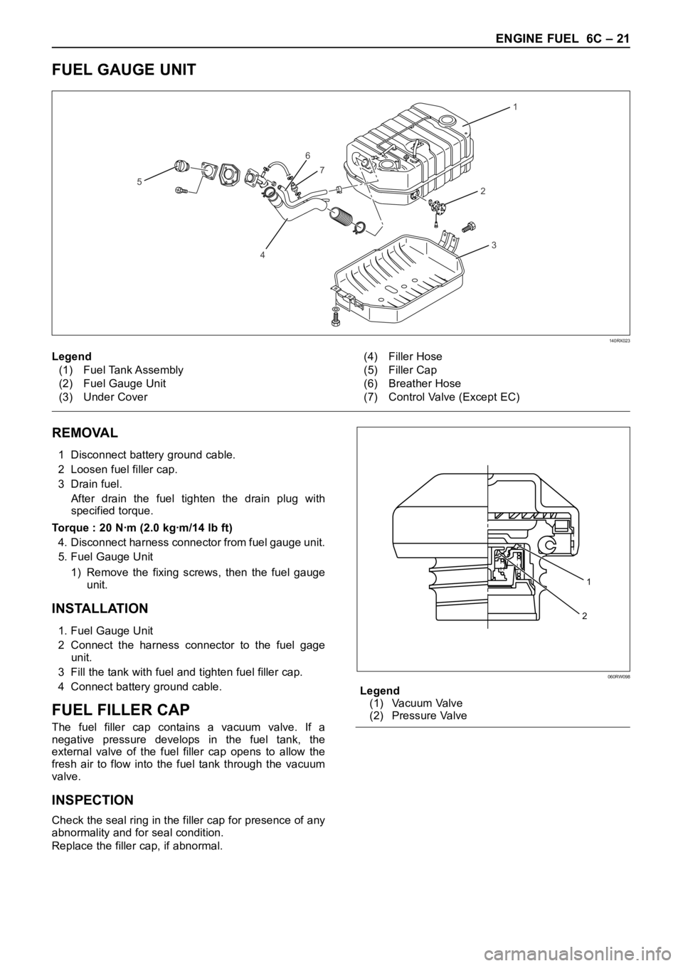
FUEL GAUGE UNIT
1
2
6
7
4
5
3
140RX023
REMOVAL
1 Disconnect battery ground cable.
2 Loosen fuel filler cap.
3 Drain fuel.
After drain the fuel tighten the drain plug with
specified torque.
Torque : 20 Nꞏm (2.0 kgꞏm/14 lb ft)
4. Disconnect harness connector from fuel gauge unit.
5. Fuel Gauge Unit
1) Remove the fixing screws, then the fuel gauge
unit.
INSTALLATION
1. Fuel Gauge Unit
2 Connect the harness connector to the fuel gage
unit.
3 Fill the tank with fuel and tighten fuel filler cap.
4 Connect battery ground cable.
FUEL FILLER CAP
The fuel filler cap contains a vacuum valve. If a
negative pressure develops in the fuel tank, the
external valve of the fuel filler cap opens to allow the
fresh air to flow into the fuel tank through the vacuum
valve.
INSPECTION
Check the seal ring in the filler cap for presence of any
abnormality and for seal condition.
Replace the filler cap, if abnormal.Legend
(1) Vacuum Valve
(2) Pressure Valve Legend
(1) Fuel Tank Assembly
(2) Fuel Gauge Unit
(3) Under Cover(4) Filler Hose
(5) Filler Cap
(6) Breather Hose
(7) Control Valve (Except EC)
1
2
060RW098
Page 5410 of 6000
ENGINE ELECTRICAL 6D – 7
ON-VEHICLE SERVICE
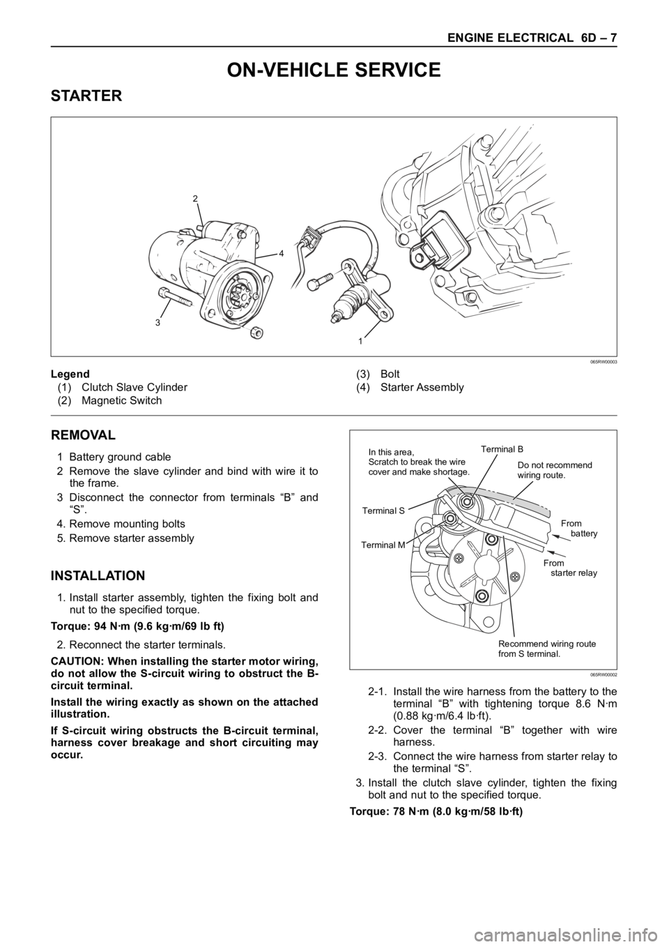
STARTER
REMOVAL
1 Battery ground cable
2 Remove the slave cylinder and bind with wire it to
the frame.
3 Disconnect the connector from terminals “B” and
“S”.
4. Remove mounting bolts
5. Remove starter assembly
INSTALLATION
1. Install starter assembly, tighten the fixing bolt and
nut to the specified torque.
Torque: 94 Nꞏm (9.6 kgꞏm/69 lb ft)
2. Reconnect the starter terminals.
CAUTION: When installing the starter motor wiring,
do not allow the S-circuit wiring to obstruct the B-
circuit terminal.
Install the wiring exactly as shown on the attached
illustration.
If S-circuit wiring obstructs the B-circuit terminal,
harness cover breakage and short circuiting may
occur.2-1. Install the wire harness from the battery to the
terminal “B” with tightening torque 8.6 Nꞏm
(0.88 kgꞏm/6.4 lbꞏft).
2-2. Cover the terminal “B” together with wire
harness.
2-3. Connect the wire harness from starter relay to
the terminal “S”.
3. Install the clutch slave cylinder, tighten the fixing
bolt and nut to the specified torque.
Torque: 78 Nꞏm (8.0 kgꞏm/58 lbꞏft)
1
32
4
Legend
(1) Clutch Slave Cylinder
(2) Magnetic Switch(3) Bolt
(4) Starter Assembly
065RW00003
Do not recommend
wiring route.
Recommend wiring route
from S terminal.From
battery
From
starter relay Terminal B
Terminal MTerminal SIn this area,
Scratch to break the wire
cover and make shortage.
065RW00002
Page 5425 of 6000
6D – 22 ENGINE ELECTRICAL
1. Using a press with a socket wrench attached,
reassemble rotor and rear end cover assembly in
the front cover.2. Install pulley on the rotor.
Secure the pulley directly in the vise between two
copper plates, and tighten nut to the specified
torque.
Torque: 111 Nꞏm (82 lb ft)
066RS022
066RS010
MAIN DATA AND SPECIFICATIONS
General Specifications
Model LR160-734B LR-170-760
Battery voltage V 12
Rated output A 60 70
Direction of rotation Clockwise
(as viewed from pulley side)
Rated rotation speed rpm 5,000
Maximum speed rpm 18,000
Page 5428 of 6000
ENGINE ELECTRICAL 6D – 25
ECT SENSOR
Measure the resistance depending on the water
temperature.
Temperature (°C) Current (mA) Resistance (k
)
20 ± 1 1.0 2.0 – 3.0
50 ± 1 1.0 0.6 – 1.0
When installing the ECT sensor, apply sealant (Loctite
#262 or equivalent) to prevent water leakage.
Torque: 8 Nꞏm (0.8 kgꞏm/69 lb in)
Legend
(1) Sealing Material
GLOW PLUG
Inspect the resistance
Resistance at normal temperature: 0.8 – 1.0
Torque: 23 Nꞏm (2.3 kgꞏm/17 lbꞏft)
GLOW PLUG RELAY
Inspect the continuity
(2) – (4) No Continuity
(1) – (3) Continuity
If battery voltage is applied to the terminal between (1)
– (3)
(2) – (4) Continuity065RW058
065RW061
1
065RW060
2 42
311
34
065RW037
Page 5452 of 6000
6E–23 4JX1–TC ENGINE DRIVEABILITY AND EMISSIONS
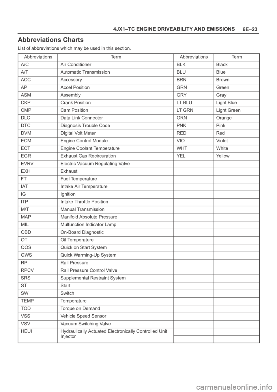
Abbreviations Charts
List of abbreviations which may be used in this section.
Abbreviations
Te r mAbbreviationsTe r m
A/CAir ConditionerBLKBlack
A/TAutomatic TransmissionBLUBlue
ACCAccessoryBRNBrown
APAccel PositionGRNGreen
ASMAssemblyGRYGray
CKPCrank PositionLT B L ULight Blue
CMPCam PositionLT G R NLight Green
DLCData Link ConnectorORNOrange
DTCDiagnosis Trouble CodePNKPink
DVMDigital Volt MeterREDRed
ECMEngine Control ModuleVIOViolet
ECTEngine Coolant TemperatureWHTWhite
EGRExhaust Gas RecircurationYELYe l l o w
EVRVElectric Vacuum Regulating Valve
EXHExhaust
FTFuel Temperature
IATIntake Air Temperature
IGIgnition
ITPIntake Throttle Position
M/TManual Transmission
MAPManifold Absolute Pressure
MILMulfunction Indicator Lamp
OBDOn-Board Diagnostic
OTOil Temperature
QOSQuick on Start System
QWSQuick Warming-Up System
RPRail Pressure
RPCVRail Pressure Control Valve
SRSSupplemental Restraint System
STStart
SWSwitch
TEMPTemperature
TODTorque on Demand
VSSVehicle Speed Sensor
VSVVacuum Switching Valve
HEUIHydraulically Actuated Electronically Controlled Unit
InjectorInjector
Page 5608 of 6000
6E–179 4JX1–TC ENGINE DRIVEABILITY AND EMISSIONS
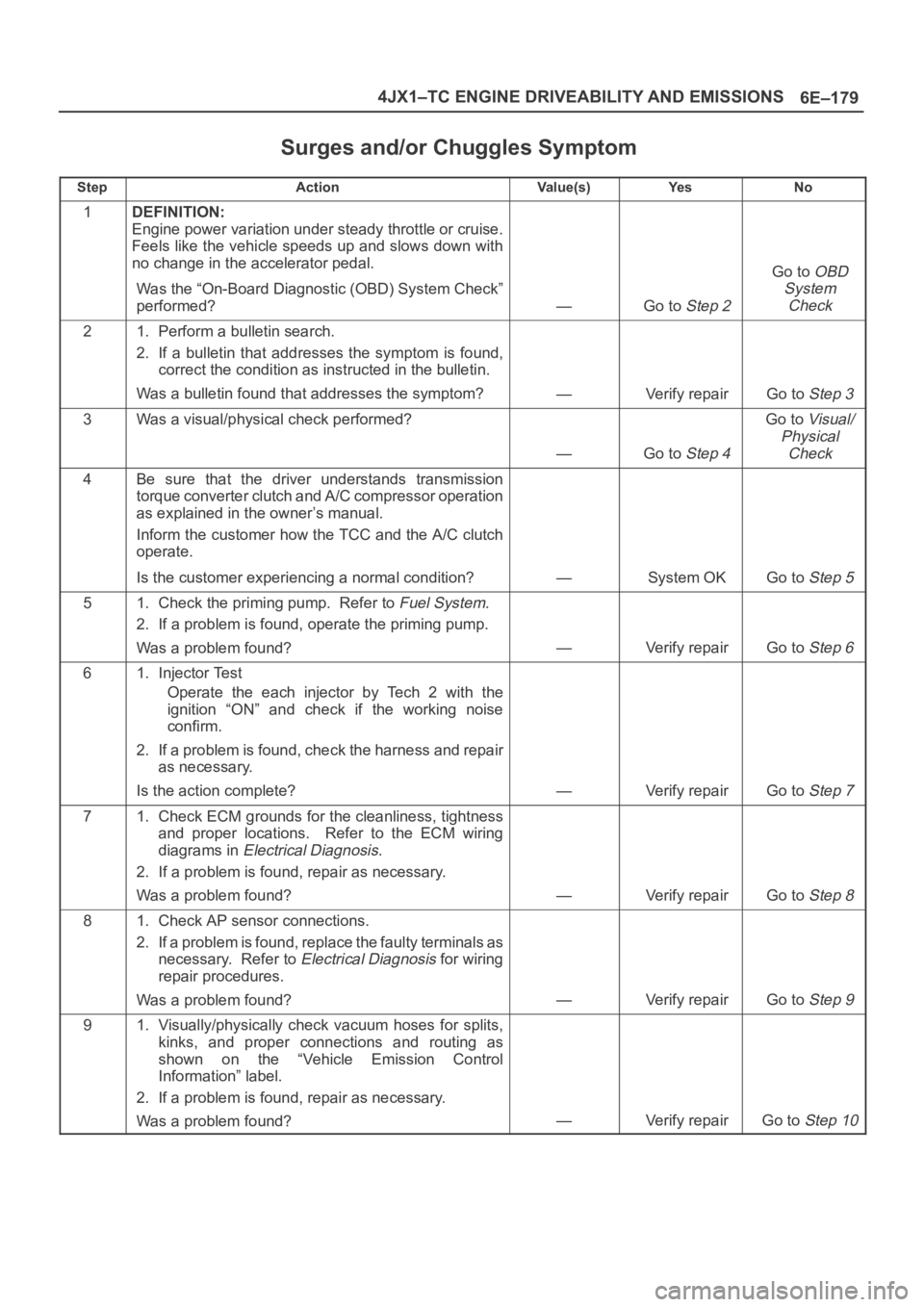
Surges and/or Chuggles Symptom
StepActionVa l u e ( s )Ye sNo
1DEFINITION:
Engine power variation under steady throttle or cruise.
Feels like the vehicle speeds up and slows down with
no change in the accelerator pedal.
Was the “On-Board Diagnostic (OBD) System Check”
performed?
—Go to Step 2
Go to OBD
System
Check
21. Perform a bulletin search.
2. If a bulletin that addresses the symptom is found,
correct the condition as instructed in the bulletin.
Was a bulletin found that addresses the symptom?
—Verify repairGo to Step 3
3Was a visual/physical check performed?
—Go to Step 4
Go to Visual/
Physical
Check
4Be sure that the driver understands transmission
torque converter clutch and A/C compressor operation
as explained in the owner’s manual.
Inform the customer how the TCC and the A/C clutch
operate.
Is the customer experiencing a normal condition?
—System OKGo to Step 5
51. Check the priming pump. Refer to Fuel System.
2. If a problem is found, operate the priming pump.
Was a problem found?
—Verify repairGo to Step 6
61. Injector Test
Operate the each injector by Tech 2 with the
ignition “ON” and check if the working noise
confirm.
2. If a problem is found, check the harness and repair
as necessary.
Is the action complete?
—Verify repairGo to Step 7
71. Check ECM grounds for the cleanliness, tightness
and proper locations. Refer to the ECM wiring
diagrams in
Electrical Diagnosis.
2. If a problem is found, repair as necessary.
Was a problem found?
—Verify repairGo to Step 8
81. Check AP sensor connections.
2. If a problem is found, replace the faulty terminals as
necessary. Refer to
Electrical Diagnosis for wiring
repair procedures.
Was a problem found?
—Verify repairGo to Step 9
91. Visually/physically check vacuum hoses for splits,
kinks, and proper connections and routing as
shown on the “Vehicle Emission Control
Information” label.
2. If a problem is found, repair as necessary.
Was a problem found?
—Verify repairGo to Step 10
Page 5610 of 6000
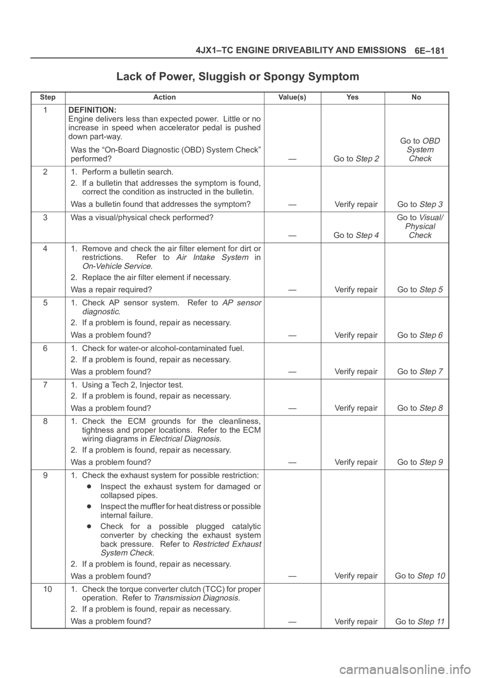
6E–181 4JX1–TC ENGINE DRIVEABILITY AND EMISSIONS
Lack of Power, Sluggish or Spongy Symptom
StepActionVa l u e ( s )Ye sNo
1DEFINITION:
Engine delivers less than expected power. Little or no
increase in speed when accelerator pedal is pushed
down part-way.
Was the “On-Board Diagnostic (OBD) System Check”
performed?
—Go to Step 2
Go to OBD
System
Check
21. Perform a bulletin search.
2. If a bulletin that addresses the symptom is found,
correct the condition as instructed in the bulletin.
Was a bulletin found that addresses the symptom?
—Verify repairGo to Step 3
3Was a visual/physical check performed?
—Go to Step 4
Go to Visual/
Physical
Check
41. Remove and check the air filter element for dirt or
restrictions. Refer to
Air Intake System in
On-Vehicle Service.
2. Replace the air filter element if necessary.
Was a repair required?
—Verify repairGo to Step 5
51. Check AP sensor system. Refer to AP sensor
diagnostic
.
2. If a problem is found, repair as necessary.
Was a problem found?
—Verify repairGo to Step 6
61. Check for water-or alcohol-contaminated fuel.
2. If a problem is found, repair as necessary.
Was a problem found?
—Verify repairGo to Step 7
71. Using a Tech 2, Injector test.
2. If a problem is found, repair as necessary.
Was a problem found?
—Verify repairGo to Step 8
81. Check the ECM grounds for the cleanliness,
tightness and proper locations. Refer to the ECM
wiring diagrams in
Electrical Diagnosis.
2. If a problem is found, repair as necessary.
Was a problem found?
—Verify repairGo to Step 9
91. Check the exhaust system for possible restriction:
Inspect the exhaust system for damaged or
collapsed pipes.
Inspect the muffler for heat distress or possible
internal failure.
Check for a possible plugged catalytic
converter by checking the exhaust system
back pressure. Refer to
Restricted Exhaust
System Check
.
2. If a problem is found, repair as necessary.
Was a problem found?
—Verify repairGo to Step 10
101. Check the torque converter clutch (TCC) for proper
operation. Refer to
Transmission Diagnosis.
2. If a problem is found, repair as necessary.
Was a problem found?
—Verify repairGo to Step 11
Page 5634 of 6000
6E–205 4JX1–TC ENGINE DRIVEABILITY AND EMISSIONS
Installation Procedure
1. Install the MAP sensor and bolts on the intake
manifold.
Torque: 4 Nꞏm (35 lb in)
035RW057
2. Connect the MAP sensor connector.
035RW053
3. Connect the EGR valve.
035RW054
4. Connect the negative battery cable.
Oil Temperature (OT) Sensor
Removal Procedure
1. Disconnect the negative battery cable.
2. Remove the battery.
035RW095