1998 OPEL FRONTERA torque
[x] Cancel search: torquePage 5340 of 6000
ENGINE MECHANICAL 6A – 67
12. Immediately install high pressure oil pipe and
tighten to specified torque.
Torque: 80 Nꞏm (8.1 kgꞏm / 57.9 lb ft)
13. Install cylinder head noise insulator cover.
Refer to “Cylinder Head” in this manual.
14. Install intercooler assembly.
Refer to “Intercooler” in this manual.
15. Install air cleaner cover and air duct.
16. Use TECH2 to rewrite injector data to ECM.
For rewriting method refer to section “Data
Programming in Case of ECM Change” of 6E 4JX1
engine driveability and emissions in this manual.
NOTE:
1) On completion of servicing, bleed air from the
engine inside fuel passage by means of the priming
pump. (The priming pump should be operated more
times than in the case of conventional engines.)
2) As air is in the oil rail, it takes more time to start the
engine. Rough idling may occur while the air is
being bled completely after starting the engine, but
it does not indicate trouble.
The air will be bled and normal engine status will be
reached while the vehicle is driven for about 5 km
or engine is operated for about 5 minutes at 1500 to
2000 rpm.
3) The injector spare part will be provided for group
number B1, B2 and B3 only.
Page 5342 of 6000
ENGINE MECHANICAL 6A – 69
INSTALLATION
1. Install relief valve (if it was removed).
Torque: 30 Nꞏm (3.1 kgꞏm / 22 lb ft)
2. Insert O-ring to strainer, install strainer and tighten
to specified torque.
Torque: 20 Nꞏm (2.0 kgꞏm / 14.5 lb ft)
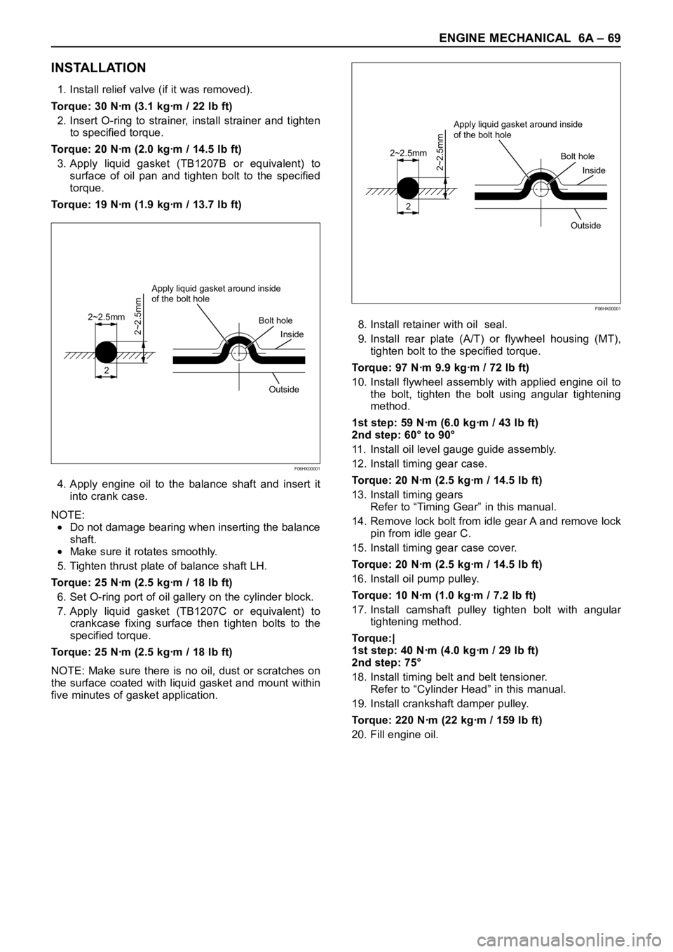
3. Apply liquid gasket (TB1207B or equivalent) to
surface of oil pan and tighten bolt to the specified
torque.
Torque: 19 Nꞏm (1.9 kgꞏm / 13.7 lb ft)
4. Apply engine oil to the balance shaft and insert it
into crank case.
NOTE:
Do not damage bearing when inserting the balance
shaft.
Make sure it rotates smoothly.
5. Tighten thrust plate of balance shaft LH.
Torque: 25 Nꞏm (2.5 kgꞏm / 18 lb ft)
6. Set O-ring port of oil gallery on the cylinder block.
7. Apply liquid gasket (TB1207C or equivalent) to
crankcase fixing surface then tighten bolts to the
specified torque.
Torque: 25 Nꞏm (2.5 kgꞏm / 18 lb ft)
NOTE: Make sure there is no oil, dust or scratches on
the surface coated with liquid gasket and mount within
five minutes of gasket application.8. Install retainer with oil seal.
9. Install rear plate (A/T) or flywheel housing (MT),
tighten bolt to the specified torque.
Torque: 97 Nꞏm 9.9 kgꞏm / 72 lb ft)
10. Install flywheel assembly with applied engine oil to
the bolt, tighten the bolt using angular tightening
method.
1st step: 59 Nꞏm (6.0 kgꞏm / 43 lb ft)
2nd step: 60° to 90°
11. Install oil level gauge guide assembly.
12. Install timing gear case.
Torque: 20 Nꞏm (2.5 kgꞏm / 14.5 lb ft)
13. Install timing gears
Refer to “Timing Gear” in this manual.
14. Remove lock bolt from idle gear A and remove lock
pin from idle gear C.
15. Install timing gear case cover.
Torque: 20 Nꞏm (2.5 kgꞏm / 14.5 lb ft)
16. Install oil pump pulley.
Torque: 10 Nꞏm (1.0 kgꞏm / 7.2 lb ft)
17. Install camshaft pulley tighten bolt with angular
tightening method.
To r q u e : |
1st step: 40 Nꞏm (4.0 kgꞏm / 29 lb ft)
2nd step: 75°
18. Install timing belt and belt tensioner.
Refer to “Cylinder Head” in this manual.
19. Install crankshaft damper pulley.
Torque: 220 Nꞏm (22 kgꞏm / 159 lb ft)
20. Fill engine oil.
2
2~2.5mm
2~2.5mm
Apply liquid gasket around inside
of the bolt hole
Bolt hole
Inside
Outside
F06HX00001
2
2~2.5mm
2~2.5mm
Apply liquid gasket around inside
of the bolt hole
Bolt hole
Inside
Outside
F06HX00001
Page 5345 of 6000
6A – 72 ENGINE MECHANICAL
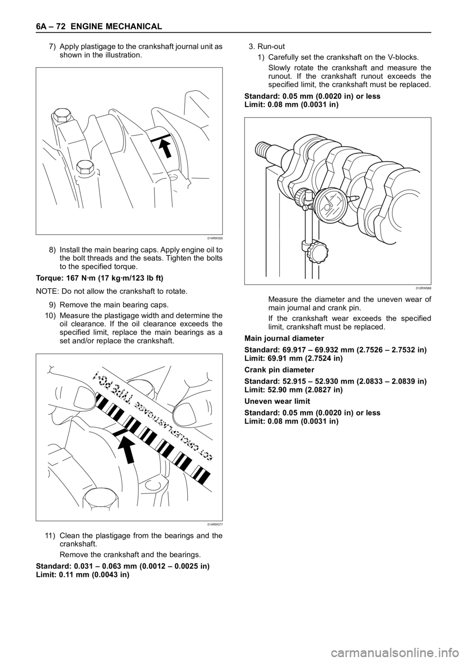
7) Apply plastigage to the crankshaft journal unit as
shown in the illustration.
8) Install the main bearing caps. Apply engine oil to
the bolt threads and the seats. Tighten the bolts
to the specified torque.
Torque: 167 Nꞏm (17 kgꞏm/123 lb ft)
NOTE: Do not allow the crankshaft to rotate.
9) Remove the main bearing caps.
10) Measure the plastigage width and determine the
oil clearance. If the oil clearance exceeds the
specified limit, replace the main bearings as a
set and/or replace the crankshaft.
11) Clean the plastigage from the bearings and the
crankshaft.
Remove the crankshaft and the bearings.
Standard: 0.031 – 0.063 mm (0.0012 – 0.0025 in)
Limit: 0.11 mm (0.0043 in)3. Run-out
1) Carefully set the crankshaft on the V-blocks.
Slowly rotate the crankshaft and measure the
runout. If the crankshaft runout exceeds the
specified limit, the crankshaft must be replaced.
Standard: 0.05 mm (0.0020 in) or less
Limit: 0.08 mm (0.0031 in)
Measure the diameter and the uneven wear of
main journal and crank pin.
If the crankshaft wear exceeds the specified
limit, crankshaft must be replaced.
Main journal diameter
Standard: 69.917 – 69.932 mm (2.7526 – 2.7532 in)
Limit: 69.91 mm (2.7524 in)
Crank pin diameter
Standard: 52.915 – 52.930 mm (2.0833 – 2.0839 in)
Limit: 52.90 mm (2.0827 in)
Uneven wear limit
Standard: 0.05 mm (0.0020 in) or less
Limit: 0.08 mm (0.0031 in)
014RW055
014RW077
012RW068
Page 5348 of 6000
ENGINE MECHANICAL 6A – 75
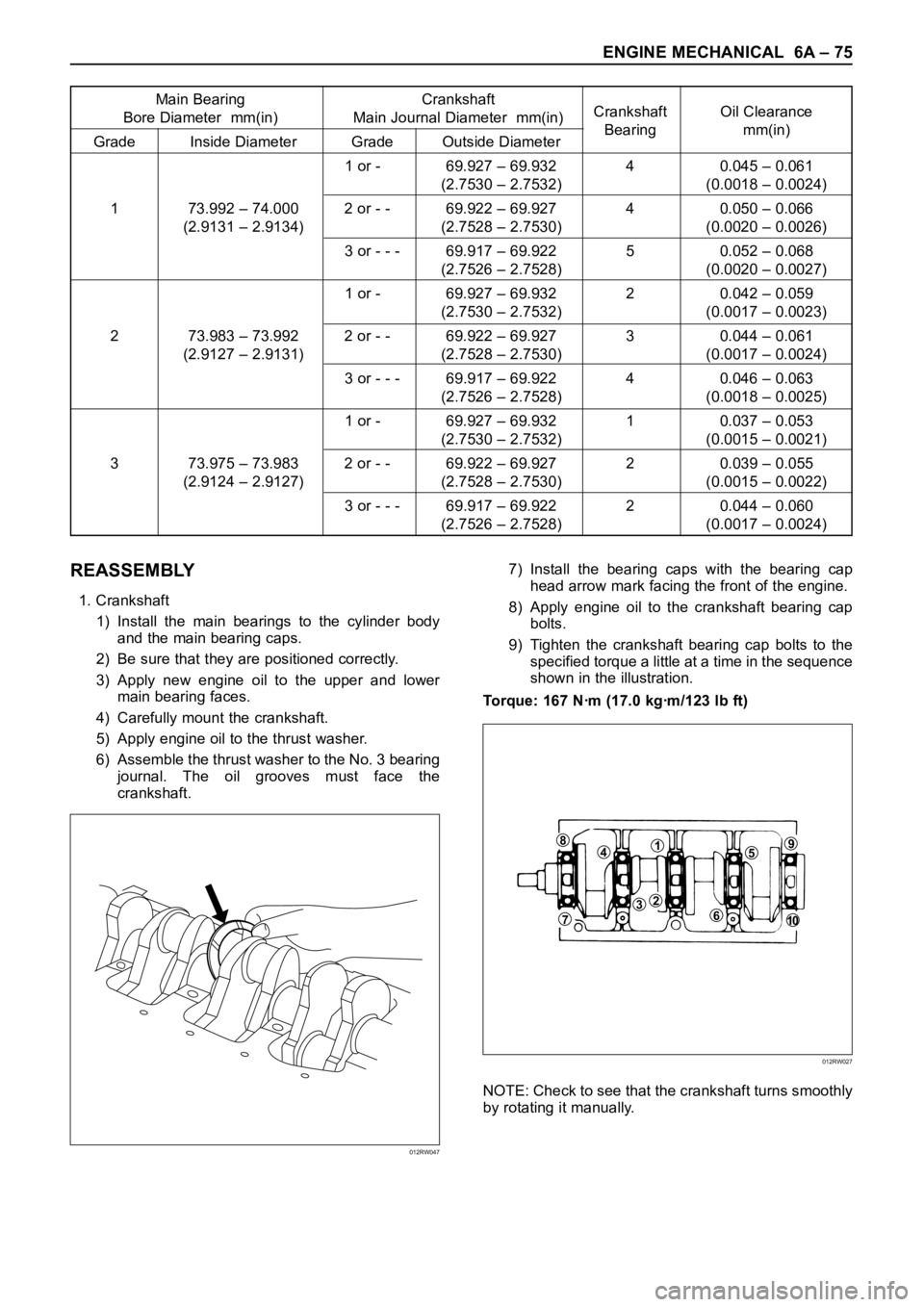
Main Bearing Crankshaft
Bore Diameter mm(in) Main Journal Diameter mm(in)Crankshaft Oil Clearance
Grade Inside Diameter Grade Outside DiameterBearing mm(in)
1 or - 69.927 – 69.932 4 0.045 – 0.061
(2.7530 – 2.7532) (0.0018 – 0.0024)
1 73.992 – 74.000 2 or - - 69.922 – 69.927 4 0.050 – 0.066
(2.9131 – 2.9134) (2.7528 – 2.7530) (0.0020 – 0.0026)
3 or - - - 69.917 – 69.922 5 0.052 – 0.068
(2.7526 – 2.7528) (0.0020 – 0.0027)
1 or - 69.927 – 69.932 2 0.042 – 0.059
(2.7530 – 2.7532) (0.0017 – 0.0023)
2 73.983 – 73.992 2 or - - 69.922 – 69.927 3 0.044 – 0.061
(2.9127 – 2.9131) (2.7528 – 2.7530) (0.0017 – 0.0024)
3 or - - - 69.917 – 69.922 4 0.046 – 0.063
(2.7526 – 2.7528) (0.0018 – 0.0025)
1 or - 69.927 – 69.932 1 0.037 – 0.053
(2.7530 – 2.7532) (0.0015 – 0.0021)
3 73.975 – 73.983 2 or - - 69.922 – 69.927 2 0.039 – 0.055
(2.9124 – 2.9127) (2.7528 – 2.7530) (0.0015 – 0.0022)
3 or - - - 69.917 – 69.922 2 0.044 – 0.060
(2.7526 – 2.7528) (0.0017 – 0.0024)
REASSEMBLY
1. Crankshaft
1) Install the main bearings to the cylinder body
and the main bearing caps.
2) Be sure that they are positioned correctly.
3) Apply new engine oil to the upper and lower
main bearing faces.
4) Carefully mount the crankshaft.
5) Apply engine oil to the thrust washer.
6) Assemble the thrust washer to the No. 3 bearing
journal. The oil grooves must face the
crankshaft.7) Install the bearing caps with the bearing cap
head arrow mark facing the front of the engine.
8) Apply engine oil to the crankshaft bearing cap
bolts.
9) Tighten the crankshaft bearing cap bolts to the
specified torque a little at a time in the sequence
shown in the illustration.
Torque: 167 Nꞏm (17.0 kgꞏm/123 lb ft)
NOTE: Check to see that the crankshaft turns smoothly
by rotating it manually.
012RW047
84159
610
237
012RW027
Page 5349 of 6000
6A – 76 ENGINE MECHANICAL
3. Piston and Connecting Rod Assembly
1) Apply engine oil to the cylinder bores, the
connecting rod bearings and the crankshaft pins
and each piston ring and piston.
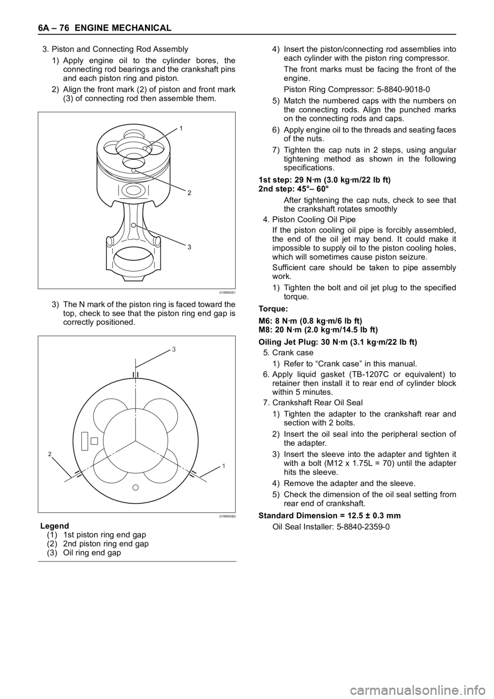
2) Align the front mark (2) of piston and front mark
(3) of connecting rod then assemble them.
3) The N mark of the piston ring is faced toward the
top, check to see that the piston ring end gap is
correctly positioned.
Legend
(1) 1st piston ring end gap
(2) 2nd piston ring end gap
(3) Oil ring end gap4) Insert the piston/connecting rod assemblies into
each cylinder with the piston ring compressor.
The front marks must be facing the front of the
engine.
Piston Ring Compressor: 5-8840-9018-0
5) Match the numbered caps with the numbers on
the connecting rods. Align the punched marks
on the connecting rods and caps.
6) Apply engine oil to the threads and seating faces
of the nuts.
7) Tighten the cap nuts in 2 steps, using angular
tightening method as shown in the following
specifications.
1st step: 29 Nꞏm (3.0 kgꞏm/22 lb ft)
2nd step: 45°– 60°
After tightening the cap nuts, check to see that
the crankshaft rotates smoothly
4. Piston Cooling Oil Pipe
If the piston cooling oil pipe is forcibly assembled,
the end of the oil jet may bend. It could make it
impossible to supply oil to the piston cooling holes,
which will sometimes cause piston seizure.
Sufficient care should be taken to pipe assembly
work.
1) Tighten the bolt and oil jet plug to the specified
torque.
To r q u e :
M6: 8 Nꞏm (0.8 kgꞏm/6 lb ft)
M8: 20 Nꞏm (2.0 kgꞏm/14.5 lb ft)
Oiling Jet Plug: 30 Nꞏm (3.1 kgꞏm/22 lb ft)
5. Crank case
1) Refer to “Crank case” in this manual.
6. Apply liquid gasket (TB-1207C or equivalent) to
retainer then install it to rear end of cylinder block
within 5 minutes.
7. Crankshaft Rear Oil Seal
1) Tighten the adapter to the crankshaft rear and
section with 2 bolts.
2) Insert the oil seal into the peripheral section of
the adapter.
3) Insert the sleeve into the adapter and tighten it
with a bolt (M12 x 1.75L = 70) until the adapter
hits the sleeve.
4) Remove the adapter and the sleeve.
5) Check the dimension of the oil seal setting from
rear end of crankshaft.
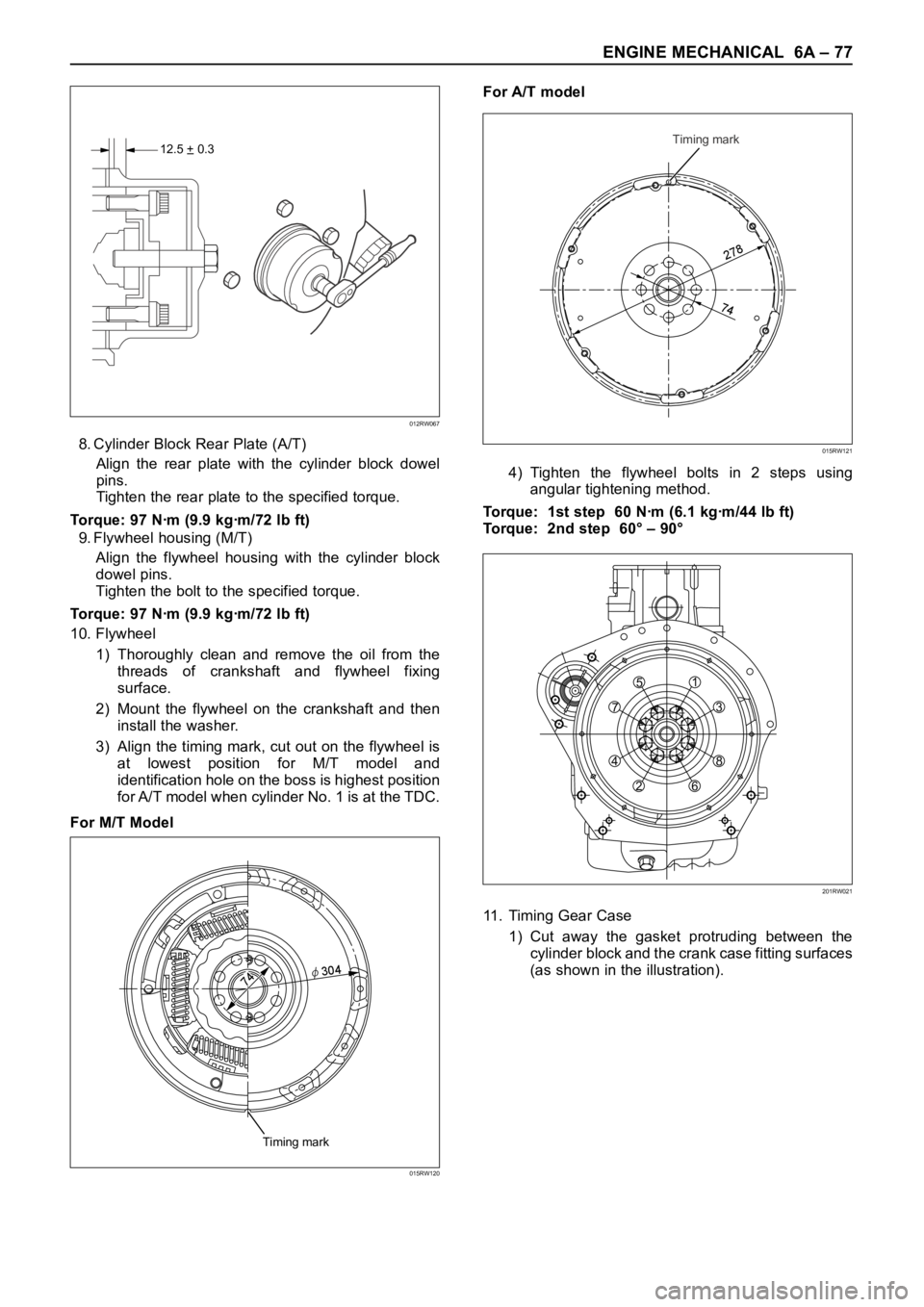
Standard Dimension = 12.5 ± 0.3 mm
Oil Seal Installer: 5-8840-2359-0
2
3
1
015RW051
3
1
2
015RW083
Page 5350 of 6000
ENGINE MECHANICAL 6A – 77
8. Cylinder Block Rear Plate (A/T)
Align the rear plate with the cylinder block dowel
pins.
Tighten the rear plate to the specified torque.
Torque: 97 Nꞏm (9.9 kgꞏm/72 lb ft)
9. Flywheel housing (M/T)
Align the flywheel housing with the cylinder block
dowel pins.
Tighten the bolt to the specified torque.
Torque: 97 Nꞏm (9.9 kgꞏm/72 lb ft)
10. Flywheel
1) Thoroughly clean and remove the oil from the
threads of crankshaft and flywheel fixing
surface.
2) Mount the flywheel on the crankshaft and then
install the washer.
3) Align the timing mark, cut out on the flywheel is
at lowest position for M/T model and
identification hole on the boss is highest position
for A/T model when cylinder No. 1 is at the TDC.
For M/T ModelFor A/T model
4) Tighten the flywheel bolts in 2 steps using
angular tightening method.
Torque: 1st step 60 Nꞏm (6.1 kgꞏm/44 lb ft)
Torque: 2nd step 60° – 90°
11. Timing Gear Case
1) Cut away the gasket protruding between the
cylinder block and the crank case fitting surfaces
(as shown in the illustration).
12.5 + 0.3–
012RW067
Timing mark
2
7
8
74
015RW121
Timing mark
74φ
30
4
015RW120
751
3
8
6 2 4
201RW021
Page 5351 of 6000
6A – 78 ENGINE MECHANICAL
2) Apply liquid gasket (TB1207B or equivalent)
between the cylinder block and the crankcase
fitting surfaces.
3) Install the timing gear case to the cylinder body.
4) Tighten the timing gear case bolt together with
the timing gear case gasket to the specified
torque.
Torque: 20 Nꞏm (2.0 kgꞏm/14.5 lbꞏft)
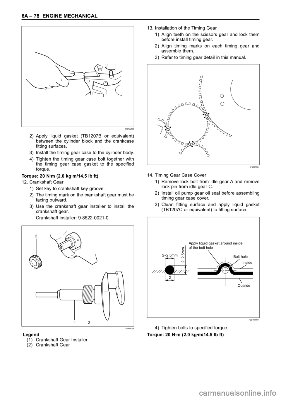
12. Crankshaft Gear
1) Set key to crankshaft key groove.
2) The timing mark on the crankshaft gear must be
facing outward.
3) Use the crankshaft gear installer to install the
crankshaft gear.
Crankshaft installer: 9-8522-0021-0
Legend
(1) Crankshaft Gear Installer
(2) Crankshaft Gear13. Installation of the Timing Gear
1) Align teeth on the scissors gear and lock them
before install timing gear.
2) Align timing marks on each timing gear and
assemble them.
3) Refer to timing gear detail in this manual.
14. Timing Gear Case Cover
1) Remove lock bolt from idle gear A and remove
lock pin from idle gear C.
2) Install oil pump gear oil seal before assembling
timing gear case cover.
3) Clean fitting surface and apply liquid gasket
(TB1207C or equivalent) to fitting surface.
4) Tighten bolts to specified torque.
Torque: 20 Nꞏm (2.0 kgꞏm/14.5 lb ft)
12
2
012RW066
2
2~2.5mm
2~2.5mm
Apply liquid gasket around inside
of the bolt hole
Bolt hole
Inside
Outside
F06HX00001
012RW024
012RW064
Page 5363 of 6000
6A – 90 ENGINE MECHANICAL
Cylinder Bore Measurement
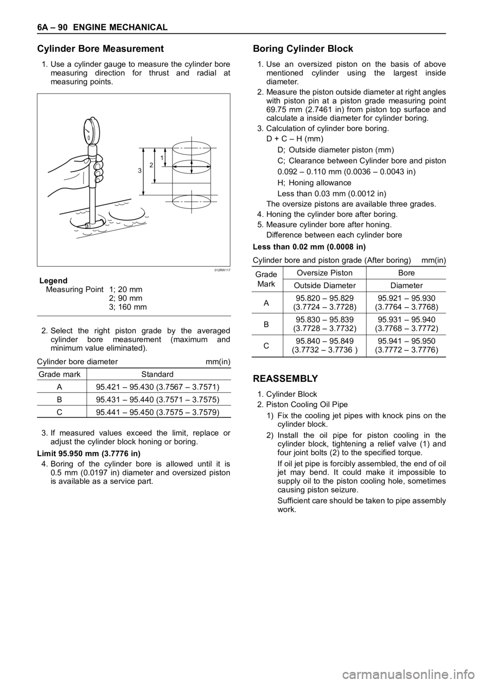
1. Use a cylinder gauge to measure the cylinder bore
measuring direction for thrust and radial at
measuring points.
Legend
Measuring Point 1; 20 mm
2; 90 mm
3; 160 mm
2. Select the right piston grade by the averaged
cylinder bore measurement (maximum and
minimum value eliminated).
Cylinder bore diameter mm(in)
Grade mark Standard
A 95.421 – 95.430 (3.7567 – 3.7571)
B 95.431 – 95.440 (3.7571 – 3.7575)
C 95.441 – 95.450 (3.7575 – 3.7579)
3. If measured values exceed the limit, replace or
adjust the cylinder block honing or boring.
Limit 95.950 mm (3.7776 in)
4. Boring of the cylinder bore is allowed until it is
0.5 mm (0.0197 in) diameter and oversized piston
is available as a service part.
Boring Cylinder Block
1. Use an oversized piston on the basis of above
mentioned cylinder using the largest inside
diameter.
2. Measure the piston outside diameter at right angles
with piston pin at a piston grade measuring point
69.75 mm (2.7461 in) from piston top surface and
calculate a inside diameter for cylinder boring.
3. Calculation of cylinder bore boring.
D + C – H (mm)
D; Outside diameter piston (mm)
C; Clearance between Cylinder bore and piston
0.092 – 0.110 mm (0.0036 – 0.0043 in)
H; Honing allowance
Less than 0.03 mm (0.0012 in)
The oversize pistons are available three grades.
4. Honing the cylinder bore after boring.
5. Measure cylinder bore after honing.
Difference between each cylinder bore
Less than 0.02 mm (0.0008 in)
Cylinder bore and piston grade (After boring) mm(in)
GradeOversize Piston Bore
Mark
Outside Diameter Diameter
A95.820 – 95.829 95.921 – 95.930
(3.7724 – 3.7728) (3.7764 – 3.7768)
B95.830 – 95.839 95.931 – 95.940
(3.7728 – 3.7732) (3.7768 – 3.7772)
C95.840 – 95.849 95.941 – 95.950
(3.7732 – 3.7736 ) (3.7772 – 3.7776)
REASSEMBLY
1. Cylinder Block
2. Piston Cooling Oil Pipe
1) Fix the cooling jet pipes with knock pins on the
cylinder block.
2) Install the oil pipe for piston cooling in the
cylinder block, tightening a relief valve (1) and
four joint bolts (2) to the specified torque.
If oil jet pipe is forcibly assembled, the end of oil
jet may bend. It could make it impossible to
supply oil to the piston cooling hole, sometimes
causing piston seizure.
Sufficient care should be taken to pipe assembly
work.
321
012RW117