Page 4086 of 6000

4B2–3 DRIVE LINE CONTROL SYSTEM (TOD)
condition, determines the optimum torque based on the
feedback control logic, and increases the torque to the
front wheels.
The control unit uses the signal from the throttle position
sensor to predict the future vehicle condition and the
intention of the driver with respect to acceleration and
deceleration, and determines the initial torque distribution
using these data and the information from the speed
sensors.
In case of small circle turning in the parking lot, for
example, the control unit minimizes the clutch pressing
force to restrict a braking phenomenon. When the ABS
becomes active, the control unit optimizes the clutch
pressing force to ensure stable braking.
TOD Indicator Control
The TOD indicator on the instrument panel informs the
driver of the current working status of the transfer unit.
The information consists of two items: the drive mode
(2H, TOD, 4L, transition) and the torque split status of the
TOD (torque distribution level). The indicator can display
occasional errors and corresponding error codes.
Page 4201 of 6000
DRIVE LINE CONTROL SYSTEM (TOD) 4B2–118
Chart 2The 4WD mode is not active.
Function of circuit—
Fail conditionThe rear wheels spin in the TOD mode, so the driving torque is not transmitted to the
front wheels. The indicator lamps will not show the 4L and TOD status.
D04RY00073
Page 4212 of 6000
4C–6
DRIVE SHAFT SYSTEM
Axle Shaft Run–out
Limit: 1.0 mm (0.039 in)
420RW025
Axle Shaft Flange Run–out
Limit: 0.08 mm (0.003 in)
420RS010
Oil Seal Replacement
Remove the oil seal carefully not to damage the bearing
holder bore .
When installing, use oil seal installer 5–8840–2310–0.
420RW026
Installation
1. Install wheel pin.
2. Install back plate.
3. Install bearing holder.
4. Install bearing.
5. Install retainer by using a bearing installer
5–8840–2296–0, press fit together with the bearing.
420RW027
6. Install snap ring.
7. Install axle shaft assembly.
NOTE: Be sure not to damage the oil seal.
8. Tighten the bearing holder mounting nut to the
specified torque.
Torque: 74Nꞏm (7.5kgꞏm/54 Ib ft)
Page 4217 of 6000
4C–11 DRIVE SHAFT SYSTEM
Reassembly
1. Install wheel pin.
Place the hub on a wood workbench or a block of
wood approx. 6” by 6” to protect the wheel stud
ends and threads.
Insert a wheel stud using a hammer.
Be sure the wheel stud is started squarely and
seats completely.
411RS005
2. Align scribe marks(1) and attach the hub to the disc,
then tighten the bolts to the specified torque.
Torque: 103 Nꞏm (10.5 kgꞏm/76 lb ft)
411RS003
3. Use installer 5–8840–2119–0 and grip
5–8840–0007–0, then install the inner bearing by
driving it into the hub.
411RW006
4. Use installer 5–8840–2118–0 and grip
5–8840–0007–0, then install the outer bearing by
driving it into the hub.
411RW007
Page 4218 of 6000

4C–12
DRIVE SHAFT SYSTEM
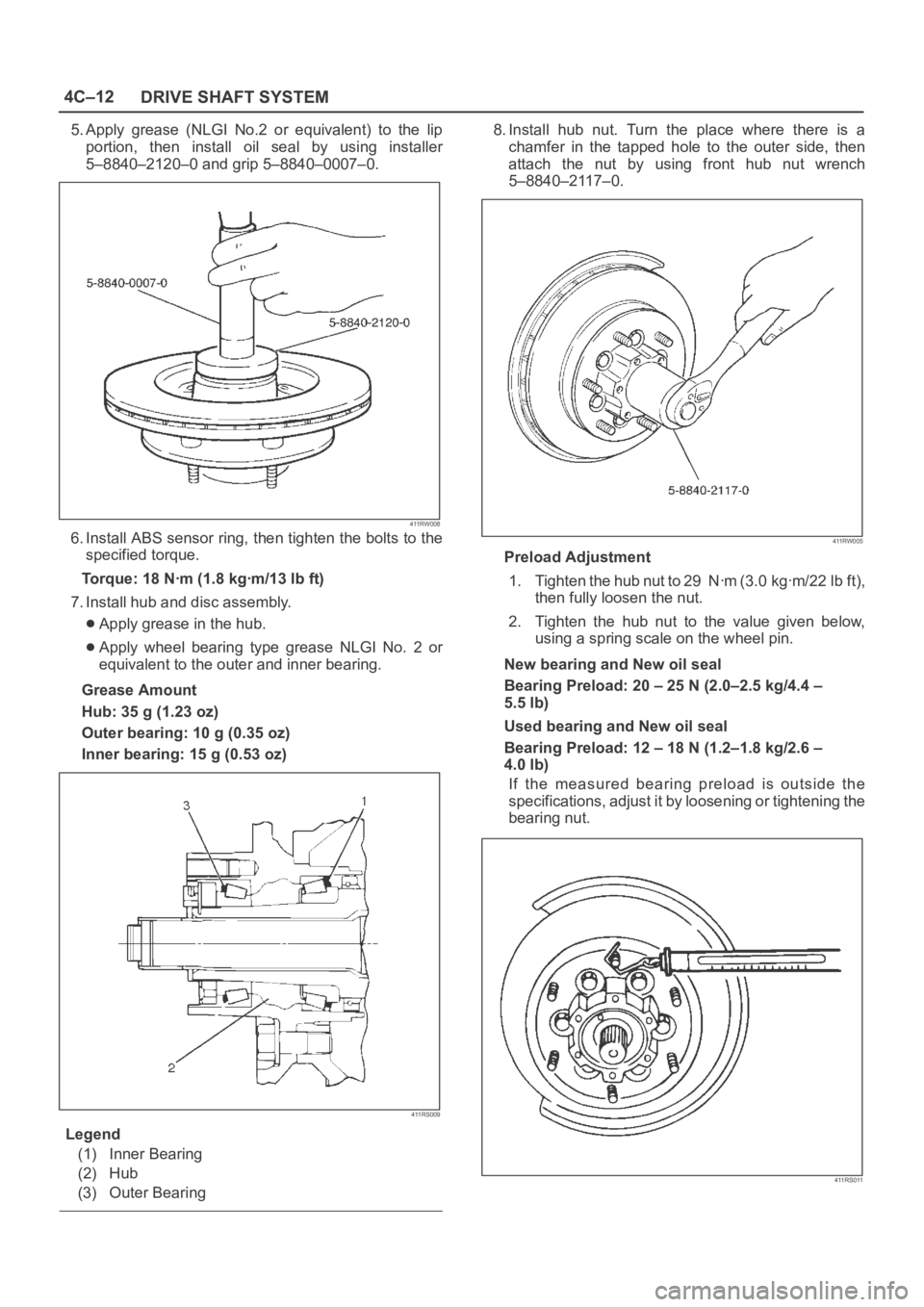
5. Apply grease (NLGI No.2 or equivalent) to the lip
portion, then install oil seal by using installer
5–8840–2120–0 and grip 5–8840–0007–0.
411RW008
6. Install ABS sensor ring, then tighten the bolts to the
specified torque.
Torque: 18 Nꞏm (1.8 kgꞏm/13 lb ft)
7. Install hub and disc assembly.
Apply grease in the hub.
Apply wheel bearing type grease NLGI No. 2 or
equivalent to the outer and inner bearing.
Grease Amount
Hub: 35 g (1.23 oz)
Outer bearing: 10 g (0.35 oz)
Inner bearing: 15 g (0.53 oz)
411RS009
Legend
(1) Inner Bearing
(2) Hub
(3) Outer Bearing
8. Install hub nut. Turn the place where there is a
chamfer in the tapped hole to the outer side, then
attach the nut by using front hub nut wrench
5–8840–2117–0.
411RW005
Preload Adjustment
1. Tighten the hub nut to 29 Nꞏm (3.0 kgꞏm/22 lb ft),
then fully loosen the nut.
2. Tighten the hub nut to the value given below,
using a spring scale on the wheel pin.
New bearing and New oil seal
Bearing Preload: 20 – 25 N (2.0–2.5 kg/4.4 –
5.5 lb)
Used bearing and New oil seal
Bearing Preload: 12 – 18 N (1.2–1.8 kg/2.6 –
4.0 lb)
If the measured bearing preload is outside the
specifications, adjust it by loosening or tightening the
bearing nut.
411RS011
Page 4219 of 6000
4C–13 DRIVE SHAFT SYSTEM
9. Install lock washer and lock screw in the following
manner.
Turn the side with larger diameter of the tapered
bore to the vehicle outer side, then attach the
washer.
If the bolt holes in the lock plate are not aligned with
the corresponding holes in the nut, reverse the lock
plate.
If the bolt holes are still out of alignment, turn in the
nut just enough to obtain alignment.
Screw is to be fastened tightly so its head may
come lower than the surface of the washer.
411RS012
10. Apply adhesive (LOCTITE 515 or equivalent) to both
joining flange faces then install hub flange.
11. Install snap ring and shim.
Adjust the clearance between the free wheeling hub
body and the snap ring.
Clearance: 0 mm–0.3 mm (0 in–0.012 in)
Shims Available: 0.2 mm, 0.3 mm, 0.5 mm,
1.0 mm (0.008 in, 0.012 in, 0.020 in, 0.039 in)
411RW002
12. Install hub cap.
13. Tighten the bolts to the specified torque.
Torque: 59 Nꞏm (6.0 kgꞏm/43 lb ft)
Page 4224 of 6000

4C–18
DRIVE SHAFT SYSTEM
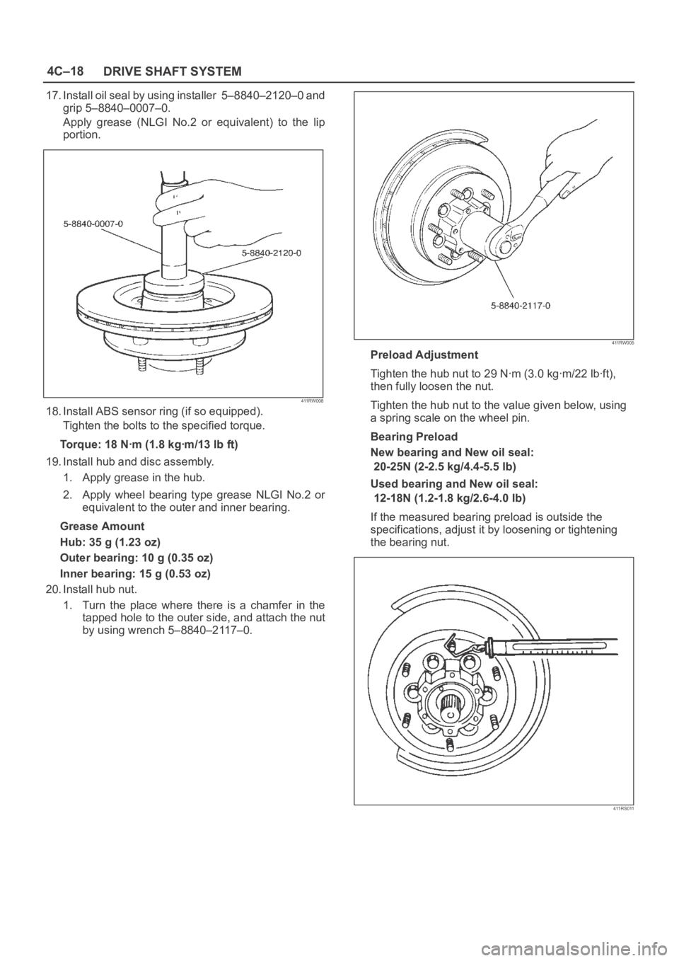
17. Install oil seal by using installer 5–8840–2120–0 and
grip 5–8840–0007–0.
Apply grease (NLGI No.2 or equivalent) to the lip
portion.
411RW008
18. Install ABS sensor ring (if so equipped).
Tighten the bolts to the specified torque.
Torque:18Nꞏm (1.8kgꞏm/13lbft)
19. Install hub and disc assembly.
1. Apply grease in the hub.
2. Apply wheel bearing type grease NLGI No.2 or
equivalent to the outer and inner bearing.
Grease Amount
Hub: 35 g (1.23 oz)
Outer bearing: 10 g (0.35 oz)
Inner bearing: 15 g (0.53 oz)
20. Install hub nut.
1. Turn the place where there is a chamfer in the
tapped hole to the outer side, and attach the nut
by using wrench 5–8840–2117–0.
411RW005
Preload Adjustment
Tighten the hub nut to 29 Nꞏm (3.0 kgꞏm/22 lbꞏft),
then fully loosen the nut.
Tighten the hub nut to the value given below, using
a spring scale on the wheel pin.
Bearing Preload
New bearing and New oil seal:
20-25N (2-2.5 kg/4.4-5.5 lb)
Used bearing and New oil seal:
12-18N (1.2-1.8 kg/2.6-4.0 lb)
If the measured bearing preload is outside the
specifications, adjust it by loosening or tightening
the bearing nut.
411RS011
Page 4225 of 6000

4C–19 DRIVE SHAFT SYSTEM
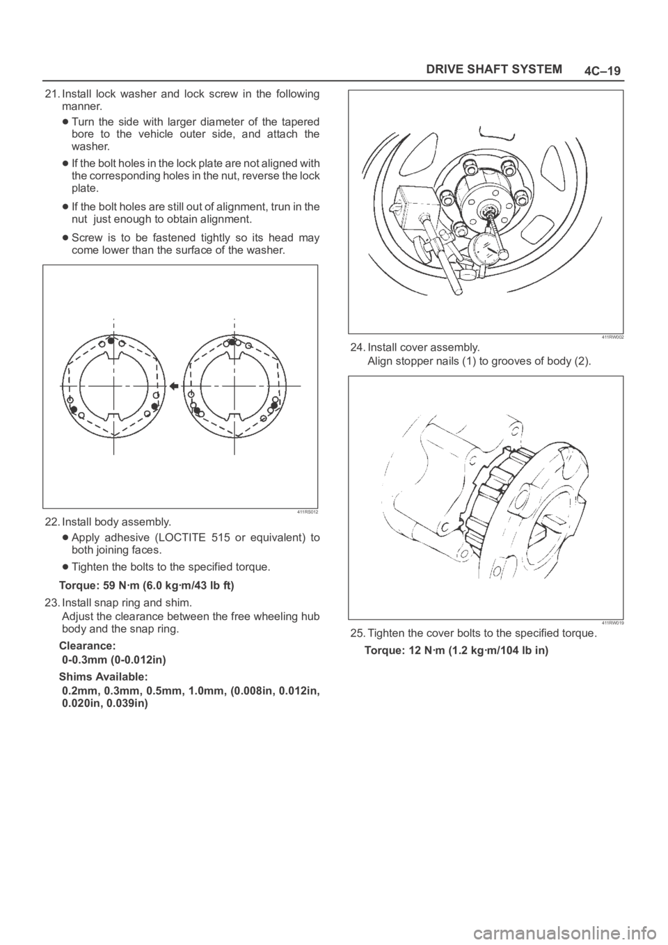
21. Install lock washer and lock screw in the following
manner.
Turn the side with larger diameter of the tapered
bore to the vehicle outer side, and attach the
washer.
If the bolt holes in the lock plate are not aligned with
the corresponding holes in the nut, reverse the lock
plate.
If the bolt holes are still out of alignment, trun in the
nut just enough to obtain alignment.
Screw is to be fastened tightly so its head may
come lower than the surface of the washer.
411RS012
22. Install body assembly.
Apply adhesive (LOCTITE 515 or equivalent) to
both joining faces.
Tighten the bolts to the specified torque.
Torque:59Nꞏm (6.0kgꞏm/43lbft)
23. Install snap ring and shim.
Adjust the clearance between the free wheeling hub
body and the snap ring.
Clearance:
0-0.3mm (0-0.012in)
Shims Available:
0.2mm, 0.3mm, 0.5mm, 1.0mm, (0.008in, 0.012in,
0.020in, 0.039in)
411RW002
24. Install cover assembly.
Align stopper nails (1) to grooves of body (2).
411RW019
25. Tighten the cover bolts to the specified torque.
Torque:12Nꞏm (1.2kgꞏm/104lbin)