1998 OPEL FRONTERA wheel torque
[x] Cancel search: wheel torquePage 2177 of 6000
7A–23 AUTOMATIC TRANSMISSION (4L30–E)
Stall Test
The stall test allows you to check the transmission for
internal abrasion and the one way clutch for slippage.
Torque converter performance can also be evaluated.
The stall test results together with the road test results will
identify transmission components requiring servicing or
adjustment.
Stall Test Procedure:
1. Check the level of the engine coolant, the engine oil,
and the automatic transmission fluid. Replenish if
necessary.
2. Block the wheels and set the parking brake.
3. Connect a tachometer to the engine.
4. Start the engine and allow it to idle until the engine
coolant temperature reaches 70 – 80
C (158 –
176
F).
5. Hold the brake pedal down as far as it will go.
6. Place the selector in the “D” range.
7. Gradually push the accelerator pedal to the floor.
The throttle valve will be fully open.
Note the engine speed at which the tachometer
needle stabilizes.
Stall Speed : 2,100
150 rpm
NOTE: Do not continuously run this test longer than 5
seconds.
8. Release the accelerator pedal.
9. Place the selector in the “N” range.
10. Run the engine at 1,200 rpm for one minute.
This will cool the transmission fluid.
11. Repeat Steps 7 – 10 for the “3”, “2”, “L” and “R”
ranges.
Line Pressure Test
The line pressure test checks oil pump and control valve
pressure regulator valve function. It will also detect oil
leakage.
Line Pressure Test Procedure:
1. Check the level of the engine coolant, the engine oil,
and the automatic transmission fluid.
Replenish if required.
2. Block the wheels and set the parking brake.
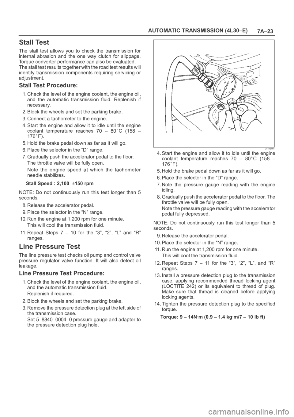
3. Remove the pressure detection plug at the left side of
the transmission case.
Set 5–8840–0004–0 pressure gauge and adapter to
the pressure detection plug hole.
241RS001
4. Start the engine and allow it to idle until the engine
coolant temperature reaches 70 – 80
C (158 –
176
F).
5. Hold the brake pedal down as far as it will go.
6. Place the selector in the “D” range.
7. Note the pressure gauge reading with the engine
idling.
8. Gradually push the accelerator pedal to the floor. The
throttle valve will be fully open.
Note the pressure gauge reading with the accelerator
pedal fully depressed.
NOTE: Do not continuously run this test longer than 5
seconds.
9. Release the accelerator pedal.
10. Place the selector in the “N” range.
11. Run the engine at 1,200 rpm for one minute.
This will cool the transmission fluid.
12. Repeat Steps 7 – 11 for the “3”, “2”, “L”, and “R”
ranges.
13. Install a pressure detection plug to the transmission
case, applying recommended thread locking agent
(LOCTITE 242) or its equivalent to thread of plug.
Make sure that thread is cleaned before applying
locking agents.
14. Tighten the pressure detection plug to the specified
torque.
Torque:9–14Nꞏm(0.9–1.4kgꞏm/7–10lbft)
Page 2186 of 6000
7A–32
AUTOMATIC TRANSMISSION (4L30–E)
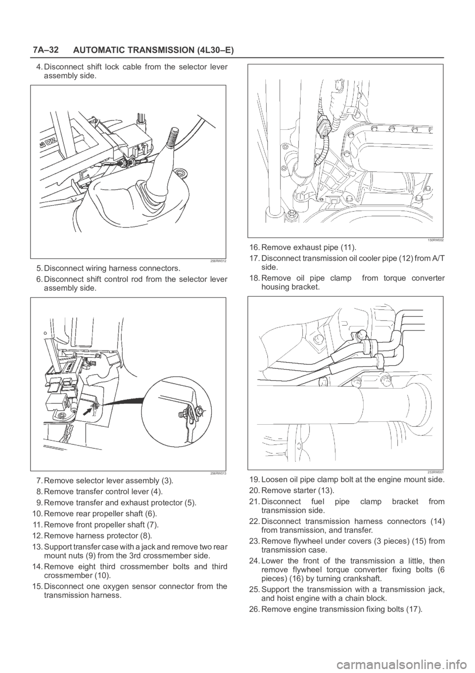
4. Disconnect shift lock cable from the selector lever
assembly side.
256RW012
5. Disconnect wiring harness connectors.
6. Disconnect shift control rod from the selector lever
assembly side.
256RW013
7. Remove selector lever assembly (3).
8. Remove transfer control lever (4).
9. Remove transfer and exhaust protector (5).
10. Remove rear propeller shaft (6).
11. Remove front propeller shaft (7).
12. Remove harness protector (8).
13. Support transfer case with a jack and remove two rear
mount nuts (9) from the 3rd crossmember side.
14. Remove eight third crossmember bolts and third
crossmember (10).
15. Disconnect one oxygen sensor connector from the
transmission harness.
150RW002
16. Remove exhaust pipe (11).
17. Disconnect transmission oil cooler pipe (12) from A/T
side.
18. Remove oil pipe clamp from torque converter
housing bracket.
253RW001
19. Loosen oil pipe clamp bolt at the engine mount side.
20. Remove starter (13).
21. Disconnect fuel pipe clamp bracket from
transmission side.
22. Disconnect transmission harness connectors (14)
from transmission, and transfer.
23. Remove flywheel under covers (3 pieces) (15) from
transmission case.
24. Lower the front of the transmission a little, then
remove flywheel torque converter fixing bolts (6
pieces) (16) by turning crankshaft.
25. Support the transmission with a transmission jack,
and hoist engine with a chain block.
26. Remove engine transmission fixing bolts (17).
Page 2187 of 6000
7A–33 AUTOMATIC TRANSMISSION (4L30–E)
27. Remove transmission assembly (18).
Installation
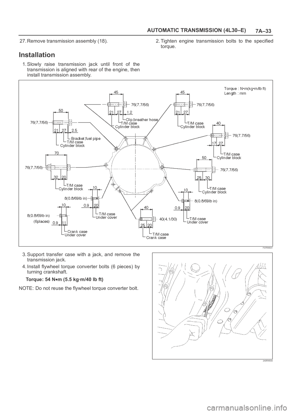
1. Slowly raise transmission jack until front of the
transmission is aligned with rear of the engine, then
install transmission assembly.2. Tighten engine transmission bolts to the specified
torque.
F07RW041
3. Support transfer case with a jack, and remove the
transmission jack.
4. Install flywheel torque converter bolts (6 pieces) by
turning crankshaft.
Torque: 54 N
m (5.5 kgꞏm/40 lb ft)
NOTE: Do not reuse the flywheel torque converter bolt.
240RW005
Page 2188 of 6000
7A–34
AUTOMATIC TRANSMISSION (4L30–E)
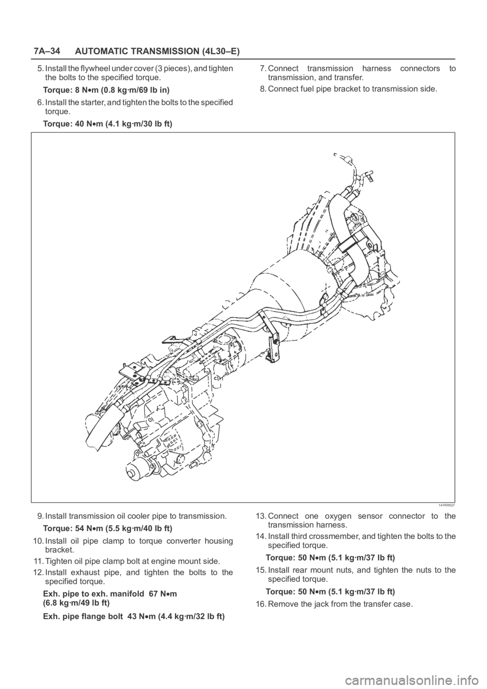
5. Install the flywheel under cover (3 pieces), and tighten
the bolts to the specified torque.
Torque: 8 N
m (0.8 kgꞏm/69 lb in)
6. Install the starter, and tighten the bolts to the specified
torque.
Torque: 40 N
m (4.1 kgꞏm/30 lb ft)7. Connect transmission harness connectors to
transmission, and transfer.
8. Connect fuel pipe bracket to transmission side.
141RW027
9. Install transmission oil cooler pipe to transmission.
Torque: 54 N
m (5.5 kgꞏm/40 lb ft)
10. Install oil pipe clamp to torque converter housing
bracket.
11. Tighten oil pipe clamp bolt at engine mount side.
12. Install exhaust pipe, and tighten the bolts to the
specified torque.
Exh. pipe to exh. manifold 67 N
m
(6.8 kgꞏm/49 lb ft)
Exh. pipe flange bolt 43 N
m (4.4 kgꞏm/32 lb ft)13. Connect one oxygen sensor connector to the
transmission harness.
14. Install third crossmember, and tighten the bolts to the
specified torque.
To r q u e : 5 0 N
m (5.1 kgꞏm/37 lb ft)
15. Install rear mount nuts, and tighten the nuts to the
specified torque.
To r q u e : 5 0 N
m (5.1 kgꞏm/37 lb ft)
16. Remove the jack from the transfer case.
Page 2524 of 6000
CLUTCH7C–15
Installation
To install, follow the removal steps in the reverse order,
noting the following points:
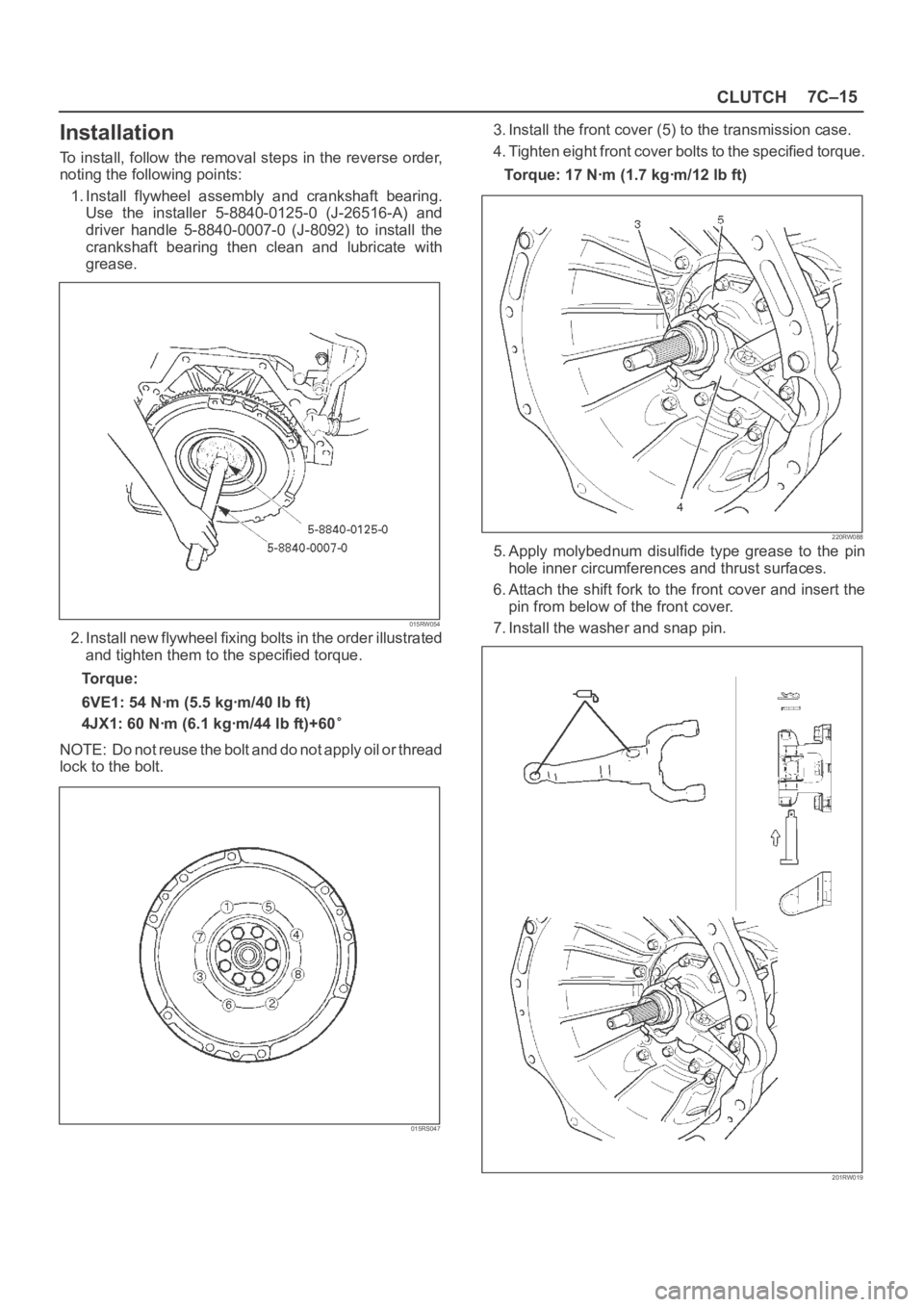
1. Install flywheel assembly and crankshaft bearing.
Use the installer 5-8840-0125-0 (J-26516-A) and
driver handle 5-8840-0007-0 (J-8092) to install the
crankshaft bearing then clean and lubricate with
grease.
015RW054
2. Install new flywheel fixing bolts in the order illustrated
and tighten them to the specified torque.
Torque:
6VE1: 54 Nꞏm (5.5 kgꞏm/40 lb ft)
4JX1: 60 Nꞏm (6.1 kgꞏm/44 lb ft)+60
NOTE: Do not reuse the bolt and do not apply oil or thread
lock to the bolt.
015RS047
3. Install the front cover (5) to the transmission case.
4. Tighten eight front cover bolts to the specified torque.
Torque: 17 Nꞏm (1.7 kgꞏm/12 lb ft)
220RW088
5. Apply molybednum disulfide type grease to the pin
hole inner circumferences and thrust surfaces.
6. Attach the shift fork to the front cover and insert the
pin from below of the front cover.
7. Install the washer and snap pin.
201RW019
Page 2557 of 6000
8A–18LIGHTING SYSTEM
Lighting Switch (Combination Switch)
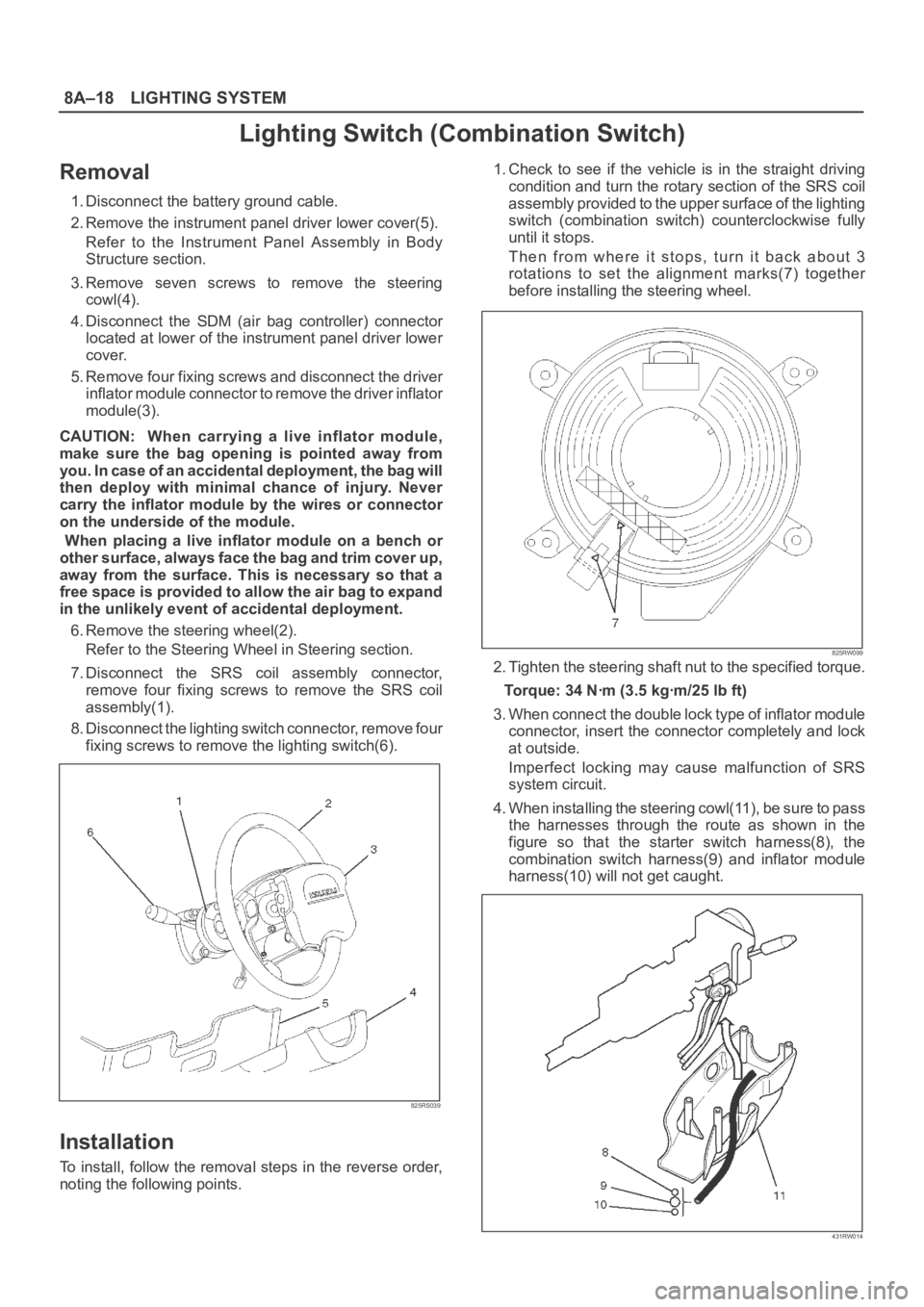
Removal
1. Disconnect the battery ground cable.
2. Remove the instrument panel driver lower cover(5).
Refer to the Instrument Panel Assembly in Body
Structure section.
3. Remove seven screws to remove the steering
cowl(4).
4. Disconnect the SDM (air bag controller) connector
located at lower of the instrument panel driver lower
cover.
5. Remove four fixing screws and disconnect the driver
inflator module connector to remove the driver inflator
module(3).
CAUTION: When carrying a live inflator module,
make sure the bag opening is pointed away from
y o u . I n c a s e o f a n a c c i d e n t a l d e p l o y m e n t , t h e b a g w i l l
then deploy with minimal chance of injury. Never
carry the inflator module by the wires or connector
on the underside of the module.
When placing a live inflator module on a bench or
other surface, always face the bag and trim cover up,
away from the surface. This is necessary so that a
free space is provided to allow the air bag to expand
in the unlikely event of accidental deployment.
6. Remove the steering wheel(2).
Refer to the Steering Wheel in Steering section.
7. Disconnect the SRS coil assembly connector,
remove four fixing screws to remove the SRS coil
assembly(1).
8. Disconnect the lighting switch connector, remove four
fixing screws to remove the lighting switch(6).
825RS039
Installation
To install, follow the removal steps in the reverse order,
noting the following points.1. Check to see if the vehicle is in the straight driving
condition and turn the rotary section of the SRS coil
assembly provided to the upper surface of the lighting
switch (combination switch) counterclockwise fully
until it stops.
Then from where it stops, turn it back about 3
rotations to set the alignment marks(7) together
before installing the steering wheel.
825RW099
2. Tighten the steering shaft nut to the specified torque.
Torque: 34 Nꞏm (3.5 kgꞏm/25 lb ft)
3. When connect the double lock type of inflator module
connector, insert the connector completely and lock
at outside.
Imperfect locking may cause malfunction of SRS
system circuit.
4. When installing the steering cowl(11), be sure to pass
the harnesses through the route as shown in the
figure so that the starter switch harness(8), the
combination switch harness(9) and inflator module
harness(10) will not get caught.
431RW014
Page 3313 of 6000
SEATS8G–1
BODY AND ACCESSORIES
SEATS
CONTENTS
Service Precaution 8G–1. . . . . . . . . . . . . . . . . . . . . .
Front Seat Assembly 8G–2. . . . . . . . . . . . . . . . . . . .
Front Seat Assembly and Associated
Parts 8G–2. . . . . . . . . . . . . . . . . . . . . . . . . . . . . . . .
Removal 8G–2. . . . . . . . . . . . . . . . . . . . . . . . . . . . .
Installation 8G–3. . . . . . . . . . . . . . . . . . . . . . . . . . . .
Disassembled View (Long Wheel Base) 8G–3. .
Disassembly 8G–4. . . . . . . . . . . . . . . . . . . . . . . . . .
Reassembly 8G–5. . . . . . . . . . . . . . . . . . . . . . . . . .
Disassembled View (Short Wheel Base) 8G–6. .
Disassembly 8G–6. . . . . . . . . . . . . . . . . . . . . . . . . .
Reassembly 8G–8. . . . . . . . . . . . . . . . . . . . . . . . . .
Power Seat Assembly 8G–9. . . . . . . . . . . . . . . . . . .
General Description 8G–9. . . . . . . . . . . . . . . . . . . . . .
Disassembled View 8G–9. . . . . . . . . . . . . . . . . . . .
Disassembly 8G–10. . . . . . . . . . . . . . . . . . . . . . . . . .
Reassembly 8G–12. . . . . . . . . . . . . . . . . . . . . . . . . .
Power Seat Switch 8G–12. . . . . . . . . . . . . . . . . . . . . .
Removal 8G–12. . . . . . . . . . . . . . . . . . . . . . . . . . . . .
Installation 8G–12. . . . . . . . . . . . . . . . . . . . . . . . . . . .
Front Tilt Motor / Rear Tilt Motor /
Slide Motor / Recliner Motor 8G–13. . . . . . . . . . . . . .
Parts Location 8G–13. . . . . . . . . . . . . . . . . . . . . . . .
Removal and Installation 8G–13. . . . . . . . . . . . . . .
Seat Heater System 8G–14. . . . . . . . . . . . . . . . . . . . .
General Description 8G–14. . . . . . . . . . . . . . . . . . . . . .
Seat Heater Switch Removal and
Installation 8G–14. . . . . . . . . . . . . . . . . . . . . . . . . . . Heat Unit Parts Location 8G–14. . . . . . . . . . . . . . . .
Heat Unit Removal and Installation 8G–14. . . . . .
Rear Seat Assembly 8G–15. . . . . . . . . . . . . . . . . . . . .
Rear Seat Assembly and Associated Parts 8G–15
Removal 8G–15. . . . . . . . . . . . . . . . . . . . . . . . . . . . .
Installation 8G–15. . . . . . . . . . . . . . . . . . . . . . . . . . . .
Disassembled View (Split Type) 8G–16. . . . . . . . .
Disassembly (Split Type) 8G–17. . . . . . . . . . . . . . .
Reassembly (Split Type) 8G–18. . . . . . . . . . . . . . . .
Disassembled View (Short Wheel Base) 8G–19. .
Disassembly 8G–19. . . . . . . . . . . . . . . . . . . . . . . . . .
Reassembly 8G–20. . . . . . . . . . . . . . . . . . . . . . . . . .
Disassembled View (Bench Type) 8G–21. . . . . . .
Disassembly (Bench Type) 8G–22. . . . . . . . . . . . .
Reassembly (Bench Type) 8G–23. . . . . . . . . . . . . .
Third Seat Assembly 8G–23. . . . . . . . . . . . . . . . . . . . .
Parts Location 8G–23. . . . . . . . . . . . . . . . . . . . . . . .
Removal 8G–23. . . . . . . . . . . . . . . . . . . . . . . . . . . . .
Installation 8G–24. . . . . . . . . . . . . . . . . . . . . . . . . . . .
Disassembled View 8G–24. . . . . . . . . . . . . . . . . . . .
Disassembly 8G–25. . . . . . . . . . . . . . . . . . . . . . . . . .
Reassembly 8G–25. . . . . . . . . . . . . . . . . . . . . . . . . .
Rear Seat Foot Rest 8G–25. . . . . . . . . . . . . . . . . . . . .
Rear Seat Foot Rest and Associated Parts 8G–25
Removal 8G–26. . . . . . . . . . . . . . . . . . . . . . . . . . . . .
Installation 8G–26
. . . . . . . . . . . . . . . . . . . . . . . . . . . .
Main Data and Specifications 8G–26. . . . . . . . . . . . .
Service Precaution
WARNING: IF SO EQUIPPED WITH A
SUPPLEMENTAL RESTRAINT SYSTEM (SRS),
REFER TO THE SRS COMPONENT AND WIRING
LOCATION VIEW IN ORDER TO DETERMINE
WHETHER YOU ARE PERFORMING SERVICE ON OR
NEAR THE SRS COMPONENTS OR THE SRS
WIRING. WHEN YOU ARE PERFORMING SERVICE
ON OR NEAR THE SRS COMPONENTS OR THE SRS
WIRING, REFER TO THE SRS SERVICE
INFORMATION. FAILURE TO FOLLOW WARNINGS
COULD RESULT IN POSSIBLE AIR BAG
DEPLOYMENT, PERSONAL INJURY, OR
OTHERWISE UNNEEDED SRS SYSTEM REPAIRS.CAUTION: Always use the correct fastener in the
proper location. When you replace a fastener, use
ONLY the exact part number for that application.
ISUZU will call out those fasteners that require a
replacement after removal. ISUZU will also call out
the fasteners that require thread lockers or thread
sealant. UNLESS OTHERWISE SPECIFIED, do not
use supplemental coatings (Paints, greases, or other
corrosion inhibitors) on threaded fasteners or
fastener joint interfaces. Generally, such coatings
adversely affect the fastener torque and the joint
clamping force, and may damage the fastener. When
you install fasteners, use the correct tightening
sequence and specifications. Following these
instructions can help you avoid damage to parts and
systems.
Page 3315 of 6000
SEATS8G–3
Installation
To install, follow the removal steps in the reverse order,
noting the following points:1. Tighten the front seat assembly fixing bolts to the
specified torque.
Torque: 40 Nꞏm (4.1 kgꞏm/30 lb ft)
2. Install the longest bolt to the rear inner side fixing
location, if this model is equipped with power seats.
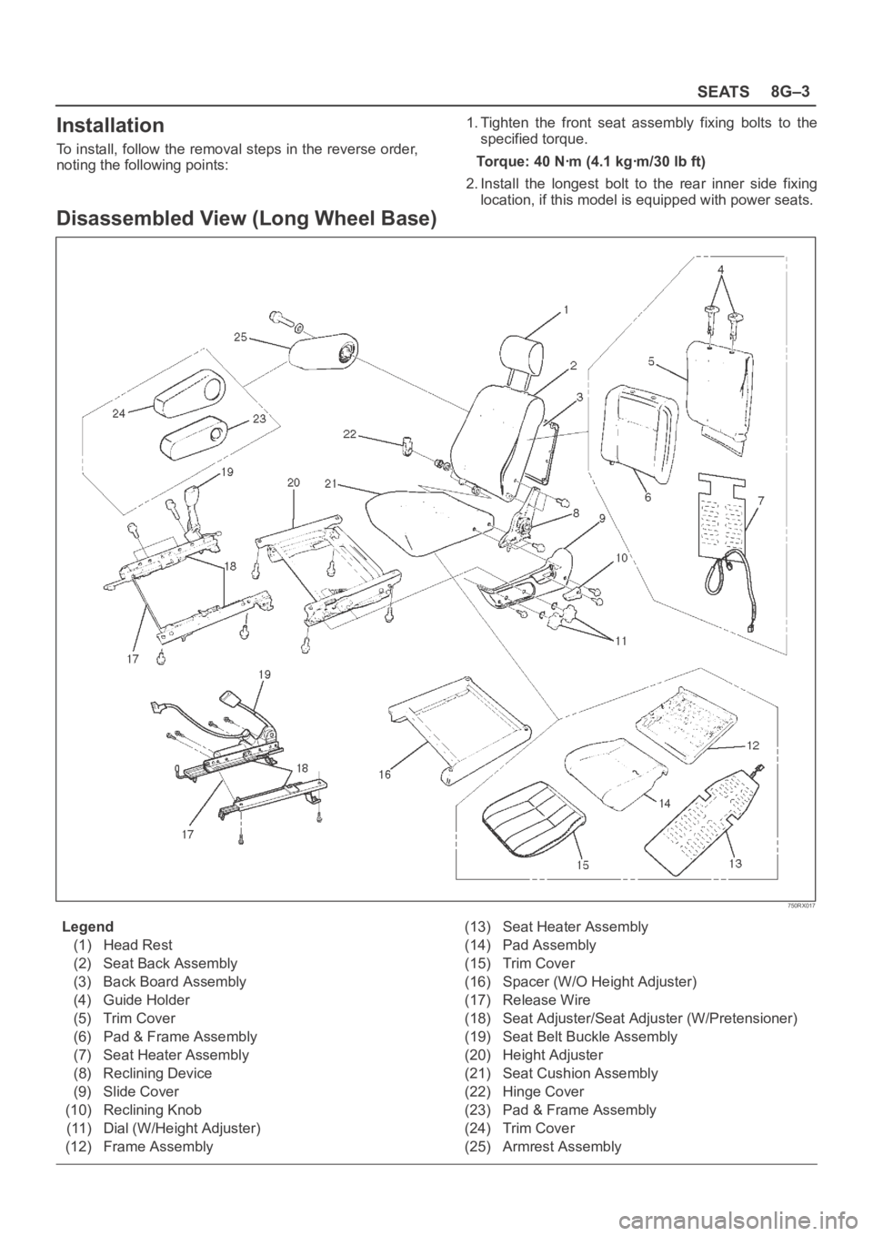
Disassembled View (Long Wheel Base)
750RX017
Legend
(1) Head Rest
(2) Seat Back Assembly
(3) Back Board Assembly
(4) Guide Holder
(5) Trim Cover
(6) Pad & Frame Assembly
(7) Seat Heater Assembly
(8) Reclining Device
(9) Slide Cover
(10) Reclining Knob
(11) Dial (W/Height Adjuster)
(12) Frame Assembly(13) Seat Heater Assembly
(14) Pad Assembly
(15) Trim Cover
(16) Spacer (W/O Height Adjuster)
(17) Release Wire
(18) Seat Adjuster/Seat Adjuster (W/Pretensioner)
(19) Seat Belt Buckle Assembly
(20) Height Adjuster
(21) Seat Cushion Assembly
(22) Hinge Cover
(23) Pad & Frame Assembly
(24) Trim Cover
(25) Armrest Assembly