1998 OPEL FRONTERA wheel torque
[x] Cancel search: wheel torquePage 5350 of 6000
ENGINE MECHANICAL 6A – 77
8. Cylinder Block Rear Plate (A/T)
Align the rear plate with the cylinder block dowel
pins.
Tighten the rear plate to the specified torque.
Torque: 97 Nꞏm (9.9 kgꞏm/72 lb ft)
9. Flywheel housing (M/T)
Align the flywheel housing with the cylinder block
dowel pins.
Tighten the bolt to the specified torque.
Torque: 97 Nꞏm (9.9 kgꞏm/72 lb ft)
10. Flywheel
1) Thoroughly clean and remove the oil from the
threads of crankshaft and flywheel fixing
surface.
2) Mount the flywheel on the crankshaft and then
install the washer.
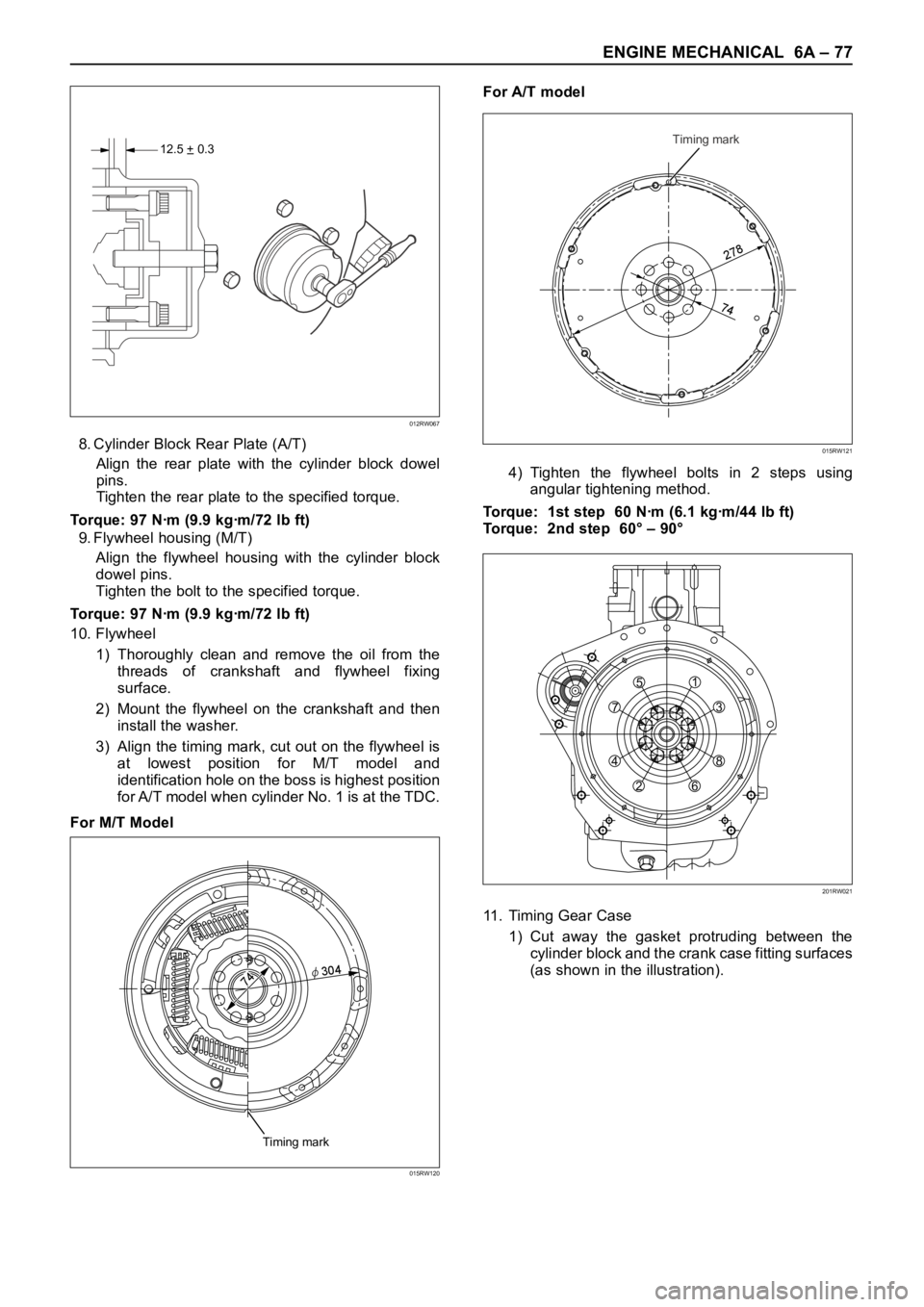
3) Align the timing mark, cut out on the flywheel is
at lowest position for M/T model and
identification hole on the boss is highest position
for A/T model when cylinder No. 1 is at the TDC.
For M/T ModelFor A/T model
4) Tighten the flywheel bolts in 2 steps using
angular tightening method.
Torque: 1st step 60 Nꞏm (6.1 kgꞏm/44 lb ft)
Torque: 2nd step 60° – 90°
11. Timing Gear Case
1) Cut away the gasket protruding between the
cylinder block and the crank case fitting surfaces
(as shown in the illustration).
12.5 + 0.3–
012RW067
Timing mark
2
7
8
74
015RW121
Timing mark
74φ
30
4
015RW120
751
3
8
6 2 4
201RW021
Page 5366 of 6000

ENGINE MECHANICAL 6A – 93
11. Use the special tool to install the crankshaft front oil
seal to timing gear case.
Front Oil Seal Installer: 5-8840-2061-0
1) Check fit-of the oil seal and gear case cover at
the front end.
Standard: 0.5 – 2.5 mm (0.0197 – 0.0984 in)
NOTE: Apply engine oil to oil seal lip before installation
of the seal.
12. Install the oil pan assembly to original position and
tighten to specified torque.
Torque: 22 Nꞏm (2.2 kgꞏm/15.9 lb ft)
13. Crankshaft Rear Oil Seal
1) Tighten the adapter to the crankshaft rear end
with 2 bolts.
2) Insert the oil seal into the adapter.
3) Insert the sleeve into the adapter and tighten it
with a bolt (M12 x 1.75L = 70) until the adapter
hits the sleeve.
4) Remove the adapter and the sleeve.
5) With the seal pressed in, check the dimension of
the oil seal outside end and crankshaft end.
Standard Dimension = 12.5 ± 0.3 mm
Oil Seal Installer: 5-8840-2359-014. Cylinder Block Rear Plate (A/T Model)
1) Tighten the cylinder block rear plate fixing bolts
to the specified torque.
Torque: 97 Nꞏm (9.9 kgꞏm/72 lb ft)
15. Flywheel Housing (M/T Model)
1) Install flywheel housing aligned with the dowel
pin on the cylinder block.
2) Tighten the flywheel housing fixing bolts to the
specified torque.
Torque: 97 Nꞏm (9.9 kgꞏm/72 lb ft)
16. Flywheel
1) Refer to “Crankshaft” in this manual.
17. Cylinder Head Assembly
1) Refer to “Cylinder Head” in this manual.
015RW074
12.5 + 0.3–
012RW067
Page 5367 of 6000
6A – 94 ENGINE MECHANICAL
OIL PUMP ASSEMBLY
2
1
5
6
3
4
012RW097
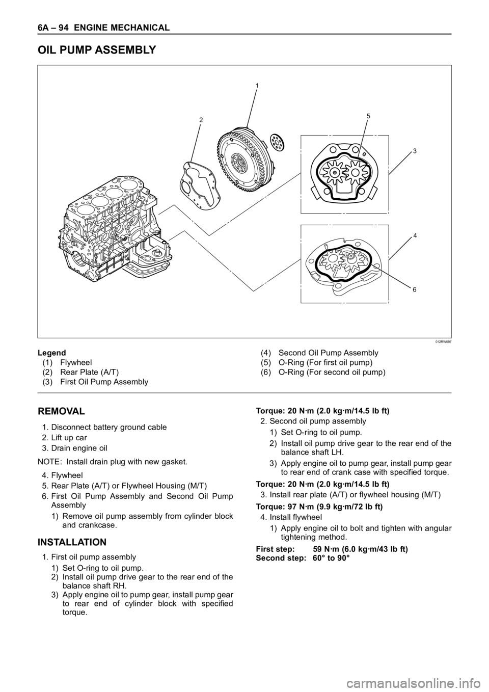
Legend
(1) Flywheel
(2) Rear Plate (A/T)
(3) First Oil Pump Assembly(4) Second Oil Pump Assembly
(5) O-Ring (For first oil pump)
(6) O-Ring (For second oil pump)
REMOVAL
1. Disconnect battery ground cable
2. Lift up car
3. Drain engine oil
NOTE: Install drain plug with new gasket.
4. Flywheel
5. Rear Plate (A/T) or Flywheel Housing (M/T)
6. First Oil Pump Assembly and Second Oil Pump
Assembly
1) Remove oil pump assembly from cylinder block
and crankcase.
INSTALLATION
1. First oil pump assembly
1) Set O-ring to oil pump.
2) Install oil pump drive gear to the rear end of the
balance shaft RH.
3) Apply engine oil to pump gear, install pump gear
to rear end of cylinder block with specified
torque.Torque: 20 Nꞏm (2.0 kgꞏm/14.5 lb ft)
2. Second oil pump assembly
1) Set O-ring to oil pump.
2) Install oil pump drive gear to the rear end of the
balance shaft LH.
3) Apply engine oil to pump gear, install pump gear
to rear end of crank case with specified torque.
Torque: 20 Nꞏm (2.0 kgꞏm/14.5 lb ft)
3. Install rear plate (A/T) or flywheel housing (M/T)
Torque: 97 Nꞏm (9.9 kgꞏm/72 lb ft)
4. Install flywheel
1) Apply engine oil to bolt and tighten with angular
tightening method.
First step: 59 Nꞏm (6.0 kgꞏm/43 lb ft)
Second step: 60° to 90°
Page 5672 of 6000
ENGINE LUBRICATION 6G – 5
OIL PUMP
REMOVAL
1. Remove battery ground cable.
2 Raise the vehicle and support with suitable safety
stand.
3. Drain engine oil.
4. Remove flywheel assembly.
5. Remove rear plate (For A/T) or flywheel housing
(For MT).
6. Remove first oil pump assembly from cylinder block
and second oil pump assembly from crank case.
INSPECTION AND REPAIR
1. Inspect flaws and/or wear on the teeth surface.
2. Inspect abnormal wear journal on the gear and in
the drive spline.
3. If problem is found during inspection, the worn parts
must be replaced.
INSTALLATION
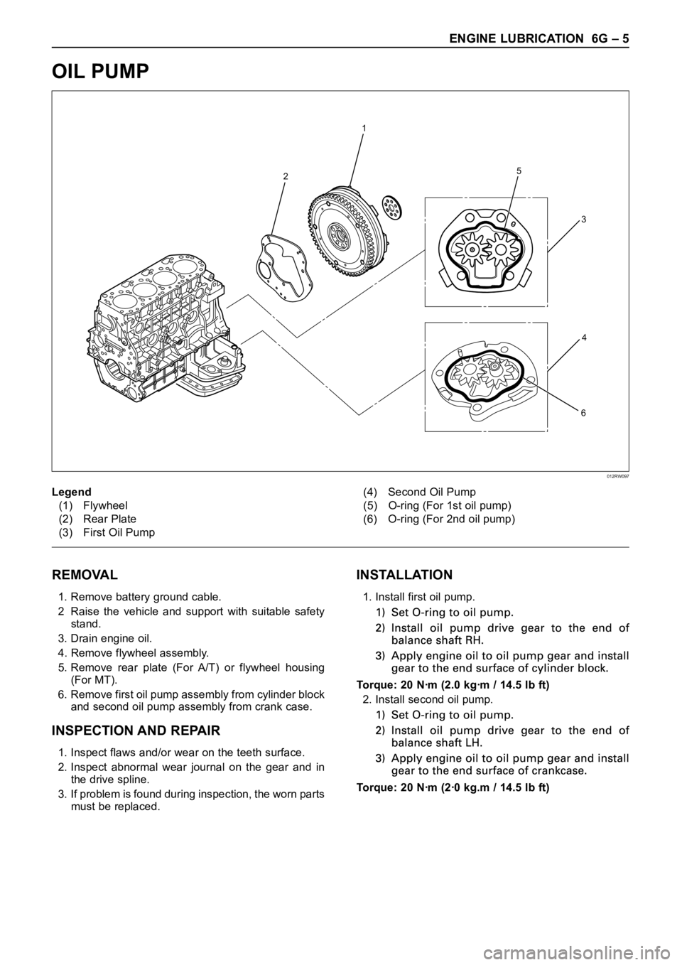
1. Install first oil pump.
Torque: 20 Nꞏm (2.0 kgꞏm / 14.5 lb ft)
2. Install second oil pump.
Torque: 20 Nꞏm (2ꞏ0 kg.m / 14.5 lb ft)
2
1
5
6
3
4
Legend
(1) Flywheel
(2) Rear Plate
(3) First Oil Pump(4) Second Oil Pump
(5) O-ring (For 1st oil pump)
(6) O-ring (For 2nd oil pump)
012RW097
Page 5692 of 6000
7A–3 AUTOMATIC TRANSMISSION (4L30–E)
Service Precaution
WARNING: IF SO EQUIPPED WITH A
SUPPLEMENTAL RESTRAINT SYSTEM (SRS),
REFER TO THE SRS COMPONENT AND WIRING
LOCATION VIEW IN ORDER TO DETERMINE
WHETHER YOU ARE PERFORMING SERVICE ON OR
NEAR THE SRS COMPONENTS OR THE SRS
WIRING. WHEN YOU ARE PERFORMING SERVICE
ON OR NEAR THE SRS COMPONENTS OR THE SRS
WIRING, REFER TO THE SRS SERVICE
INFORMATION. FAILURE TO FOLLOW WARNINGS
COULD RESULT IN POSSIBLE AIR BAG
DEPLOYMENT, PERSONAL INJURY, OR
OTHERWISE UNNEEDED SRS SYSTEM REPAIRS.CAUTION: Always use the correct fastener in the
proper location. When you replace a fastener, use
ONLY the exact part number for that application.
ISUZU will call out those fasteners that require a
replacement after removal. ISUZU will also call out
the fasteners that require thread lockers or thread
sealant. UNLESS OTHERWISE SPECIFIED, do not
use supplemental coatings (Paints, greases, or other
corrosion inhibitors) on threaded fasteners or
fastener joint interfaces. Generally, such coatings
adversely affect the fastener torque and the joint
clamping force, and may damage the fastener. When
you install fasteners, use the correct tightening
sequence and specifications. Following these
instructions can help you avoid damage to parts and
systems.
Construction
A07RS001
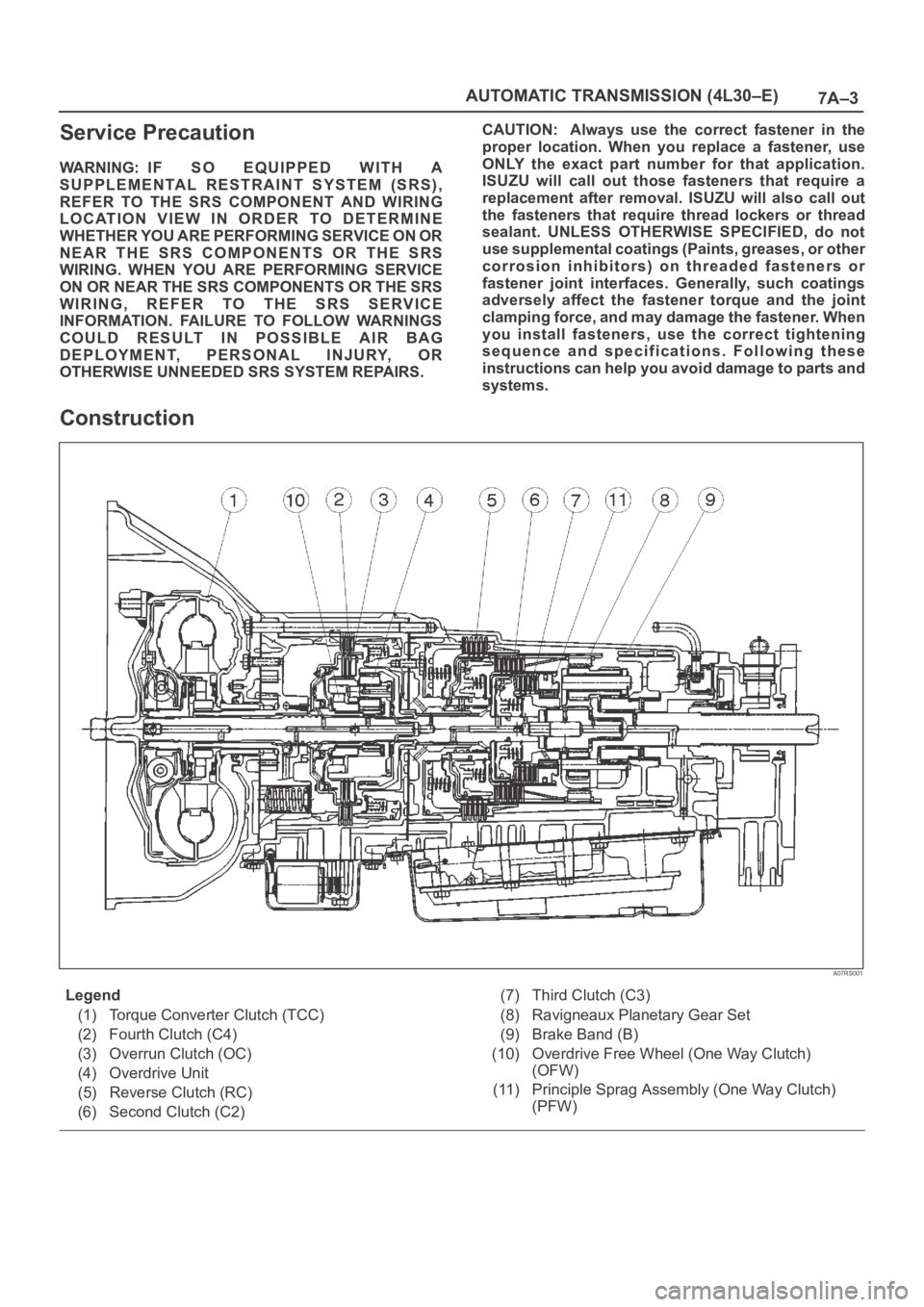
Legend
(1) Torque Converter Clutch (TCC)
(2) Fourth Clutch (C4)
(3) Overrun Clutch (OC)
(4) Overdrive Unit
(5) Reverse Clutch (RC)
(6) Second Clutch (C2)(7) Third Clutch (C3)
(8) Ravigneaux Planetary Gear Set
(9) Brake Band (B)
(10) Overdrive Free Wheel (One Way Clutch)
(OFW)
(11) Principle Sprag Assembly (One Way Clutch)
(PFW)
Page 5712 of 6000
7A–23 AUTOMATIC TRANSMISSION (4L30–E)
Stall Test
The stall test allows you to check the transmission for
internal abrasion and the one way clutch for slippage.
Torque converter performance can also be evaluated.
The stall test results together with the road test results will
identify transmission components requiring servicing or
adjustment.
Stall Test Procedure:
1. Check the level of the engine coolant, the engine oil,
and the automatic transmission fluid. Replenish if
necessary.
2. Block the wheels and set the parking brake.
3. Connect a tachometer to the engine.
4. Start the engine and allow it to idle until the engine
coolant temperature reaches 70 – 80
C (158 –
176
F).
5. Hold the brake pedal down as far as it will go.
6. Place the selector in the “D” range.
7. Gradually push the accelerator pedal to the floor.
The throttle valve will be fully open.
Note the engine speed at which the tachometer
needle stabilizes.
Stall Speed : 2,100
150 rpm
NOTE: Do not continuously run this test longer than 5
seconds.
8. Release the accelerator pedal.
9. Place the selector in the “N” range.
10. Run the engine at 1,200 rpm for one minute.
This will cool the transmission fluid.
11. Repeat Steps 7 – 10 for the “3”, “2”, “L” and “R”
ranges.
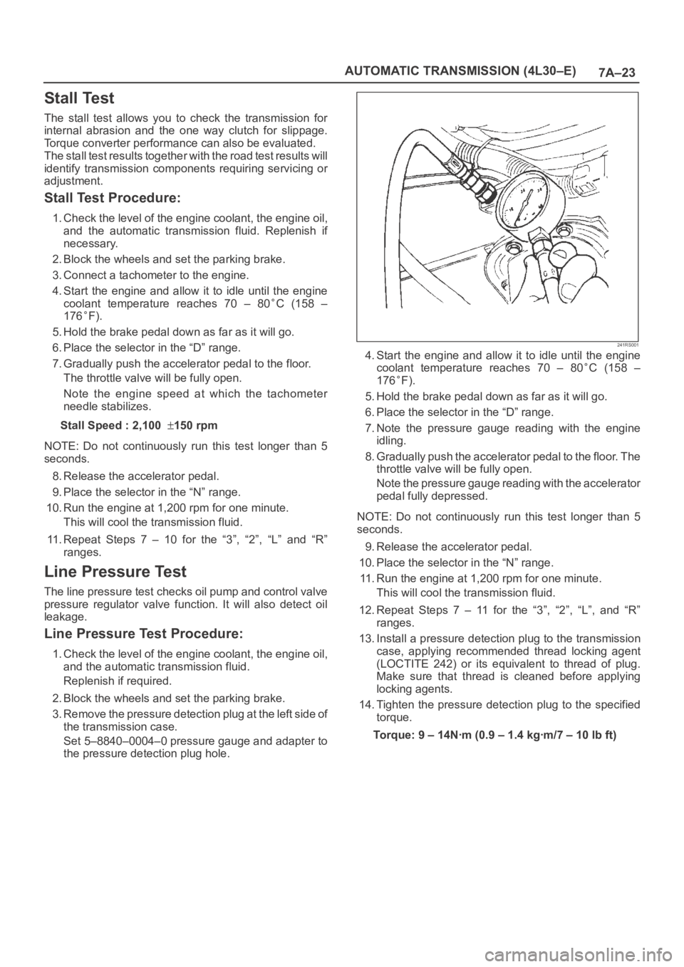
Line Pressure Test
The line pressure test checks oil pump and control valve
pressure regulator valve function. It will also detect oil
leakage.
Line Pressure Test Procedure:
1. Check the level of the engine coolant, the engine oil,
and the automatic transmission fluid.
Replenish if required.
2. Block the wheels and set the parking brake.
3. Remove the pressure detection plug at the left side of
the transmission case.
Set 5–8840–0004–0 pressure gauge and adapter to
the pressure detection plug hole.
241RS001
4. Start the engine and allow it to idle until the engine
coolant temperature reaches 70 – 80
C (158 –
176
F).
5. Hold the brake pedal down as far as it will go.
6. Place the selector in the “D” range.
7. Note the pressure gauge reading with the engine
idling.
8. Gradually push the accelerator pedal to the floor. The
throttle valve will be fully open.
Note the pressure gauge reading with the accelerator
pedal fully depressed.
NOTE: Do not continuously run this test longer than 5
seconds.
9. Release the accelerator pedal.
10. Place the selector in the “N” range.
11. Run the engine at 1,200 rpm for one minute.
This will cool the transmission fluid.
12. Repeat Steps 7 – 11 for the “3”, “2”, “L”, and “R”
ranges.
13. Install a pressure detection plug to the transmission
case, applying recommended thread locking agent
(LOCTITE 242) or its equivalent to thread of plug.
Make sure that thread is cleaned before applying
locking agents.
14. Tighten the pressure detection plug to the specified
torque.
Torque:9–14Nꞏm(0.9–1.4kgꞏm/7–10lbft)
Page 5844 of 6000
AUTOMATIC TRANSMISSION (AW30-40LE) 7A–63
F07RY00002
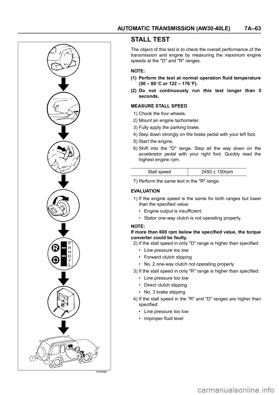
STALL TEST
The object of this test is to check the overall performance of the
transmission and engine by measuring the maximum engine
speeds at the "D" and "R" ranges.
NOTE:
(1) Perform the test at normal operation fluid temperature
(50 – 80
C or 122 – 176F).
(2) Do not continuously run this test longer than 5
seconds.
MEASURE STALL SPEED
1) Chock the four wheels.
2) Mount an engine tachometer.
3) Fully apply the parking brake.
4) Step down strongly on the brake pedal with your left foot.
5) Star t the engine.
6) Shift into the "D" range. Step all the way down on the
accelerator pedal with your right foot. Quickly read the
highest engine rpm.
7) Perform the same test in the "R" range.
EVALUATION
1) If the engine speed is the same for both ranges but lower
than the specified value:
• Engine output is insufficient.
• Stator one-way clutch is not operating properly.
NOTE:
If more than 600 rpm below the specified value, the torque
converter could be faulty.
2) If the stall speed in only "D" range is higher than specified:
• Line pressure too low
• Forward clutch slipping
• No. 2 one-way clutch not operating properly
3) If the stall speed in only "R" range is higher than specified:
• Line pressure too low
• Direct clutch slipping
• No. 3 brake slipping
4) If the stall speed in the "R" and "D" ranges are higher than
specified:
• Line pressure too low
• Improper fluid levelStall speed 2450
150rpm