Page 4228 of 6000
4C–22
DRIVE SHAFT SYSTEM
Front Drive Shaft Joint
Front Drive Shaft Joints Replace-
ment
Refer to Front Drive Axle Assembly Replacement in
this section, and refer to Front Hub and Disc in
Suspension section.
Front Hub Bearing Preload Check
Check the hub bearing preload at the wheel pin.
New bearing and New oil seal
Preload: 20 – 25 N (2.0 – 2.5 kg/4.4–5.5 lb)
New bearing and New oil seal
Preload: 12 –18 N (1.2 – 1.8 kg/2.6–4.0 lb)
411RS001
Inspection Of Shift On The Fly System
Gear Oil
412RT002
1. Open filler plug and make sure that the oil is up to the
plug port.
If the level oil is low, replenish with gear oil GL–5
grade.
2. Tighten the filler plug to specified torque.
Torque: 7.8 Nꞏm (7.9 kgꞏcm/58 lb in)
Page 4304 of 6000
TRANSFER CASE (STANDARD TYPE)
4D1–43
Main Data and Specifications
General Specifications
Ty p eW/Shift On The Fly System model
Synchronized type gears shifting between the 2 and 4 wheel drive mode.
Constant mesh type gears shifting between “low” and “high”.
WO/Shift On The Fly System model
Constant mesh type gears shifting between the 2 and 4 wheel drive mode,
and between “low” and “high”.
Control methodW/4WD Switch model
Electric control with the button switch on the instrument panel for gear
shifting between the 2 and 4 wheel drive mode.
Remote control with the gear shift lever on the floor for gear shifting
between “low and high” .
WO/4WD Switch model
Remote control with the gear shift lever on the floor for gear shifting.
Gear ratioHigh; 1.000
Low; 2.050
Oil capacity1.45 lit. (1.53 U.S. quart)
Type of lubricantEngine oil
Refer to chart in Section 0
Torque Specifications
E07RW037
Page 4322 of 6000
4D2–15 TRANSFER CASE (TOD)
4. Apply a thin coat of grease to the seal ring of each
front and rear speed sensor, and mount the sensors
carefully.
5. Tighten the bolts to the specified torque.
Torque : 5 Nꞏm (0.5 kgꞏm/43 lb in)
NOTE: Pay attention not to mount the front (or rear)
sensor to the rear (or front) sensor position.
6. Install the ball bearing (1) for the front output shaft as
flat as shown in the figure.
261RW008
7. Mount the coil assembly and tighten the nuts to the
specified torque.
Torque : 10 Nꞏm (1.0 kgꞏm/87 lb in)
8. Connect the terminal in the central connector.
NOTE: Be careful not to damage other terminals.
9. Install speed gear and tone wheel.
10. Mount the ball bearing (2) as flat as shown in the
figure.
261RW009–1
11. Using snap ring pliers, install the snap ring to the
transfer cover assembly.NOTE: Securely install the snap ring to the groove of the
transfer cover assembly.
Page 4348 of 6000
4D2–41 TRANSFER CASE (TOD)
Main Data and Specifications
Leading Particulars
Ty p eTransfer case with low range reduction mechanism
2H Rear wheel drive
TOD Electronically controlled torque split four wheel drive
4L Low-speed mechanical lock-up four wheel drive
Control systemFloor direct control
Gear ratioH1.000
L2.480
Oil quantity, Lit1.9
OilAT F D E X R O N-IIE or ATF DEXRON-III
Torque Specifications
E04RW012
Page 4413 of 6000

5B–1 ANTI–LOCK BRAKE SYSTEM
BRAKES
ANTI-LOCK BRAKE SYSTEM
CONTENTS
Service Precaution 5B–1. . . . . . . . . . . . . . . . . . . . . .
Electronic Hydraulic Control Unit 5B–2. . . . . . . . . .
Electronic Hydraulic Control Unit and
Associated Parts 5B–2. . . . . . . . . . . . . . . . . . . . . .
Removal 5B–2. . . . . . . . . . . . . . . . . . . . . . . . . . . . .
Installation 5B–2. . . . . . . . . . . . . . . . . . . . . . . . . . . .
G-Sensor 5B–3. . . . . . . . . . . . . . . . . . . . . . . . . . . . . .
Removal 5B–3. . . . . . . . . . . . . . . . . . . . . . . . . . . . .
Inspection and Repair 5B–3. . . . . . . . . . . . . . . . . .
Installation 5B–3. . . . . . . . . . . . . . . . . . . . . . . . . . . .
Front Wheel Speed Sensor 5B–4. . . . . . . . . . . . . . . Front Wheel Speed Sensor and
Associated Parts 5B–4. . . . . . . . . . . . . . . . . . . . . .
Removal 5B–4. . . . . . . . . . . . . . . . . . . . . . . . . . . . .
Inspection and Repair 5B–5. . . . . . . . . . . . . . . . . .
Installation 5B–5. . . . . . . . . . . . . . . . . . . . . . . . . . . .
Rear Wheel Speed Sensor 5B–6. . . . . . . . . . . . . . .
Rear Wheel Speed Sensor and
Associated Parts 5B–6. . . . . . . . . . . . . . . . . . . . . .
Removal 5B–6. . . . . . . . . . . . . . . . . . . . . . . . . . . . .
Inspection and Repair 5B–6. . . . . . . . . . . . . . . . . .
Installation 5B–6. . . . . . . . . . . . . . . . . . . . . . . . . . . .
Service Precaution
WARNING: IF SO EQUIPPED WITH A
SUPPLEMENTAL RESTRAINT SYSTEM(SRS),
REFER TO THE SRS COMPONENT AND WIRING
LOCATION VIEW IN ORDER TO DETERMINE
WHETHER YOU ARE PERFORMING SERVICE ON OR
NEAR THE SRS COMPONENTS OR THE SRS
WIRING. WHEN YOU ARE PERFORMING SERVICE
ON OR NEAR THE SRS COMPONENTS OR THE SRS
WIRING, REFER TO THE SRS SERVICE
INFORMATION. FAILURE TO FOLLOW WARNINGS
COULD RESULT IN POSSIBLE AIR BAG
DEPLOYMENT, PERSONAL INJURY, OR
OTHERWISE UNNEEDED SRS SYSTEM REPAIRS.
CAUTION: Always use the correct fastener in the
proper location. When you replace a fastener, use
ONLY the exact part number for that application.
ISUZU will call out those fasteners that require a
replacement after removal. ISUZU will also call out
the fasteners that require thread lockers or thread
sealant. UNLESS OTHERWISE SPECIFIED, do not
use supplemental coatings (Paints, greases, or other
corrosion inhibitors) on threaded fasteners or
fastener joint interfaces. Generally, such coatings
adversely affect the fastener torque and the joint
clamping force, and may damage the fastener. When
you install fasteners, use the correct tightening
sequence and specifications. Following these
instructions can help you avoid damage to parts and
systems.CAUTION: Replace all components included in
repair kits used to service this system. Lubricate
rubber parts with clean, fresh brake fluid to ease
assembly. Do not use shop air with in–line
lubricators on brake parts, as damage to rubber
components may result. If any hydraulic component
is removed or brake line disconnected, it may be
necessary to bleed part or all of the brake system.
NOTE: The use of rubber hoses or parts other than those
furnished specifically for the Anti–lock Brake System may
lead to functional problems requiring major overhaul.
Page 4418 of 6000

5B–6ANTI–LOCK BRAKE SYSTEM
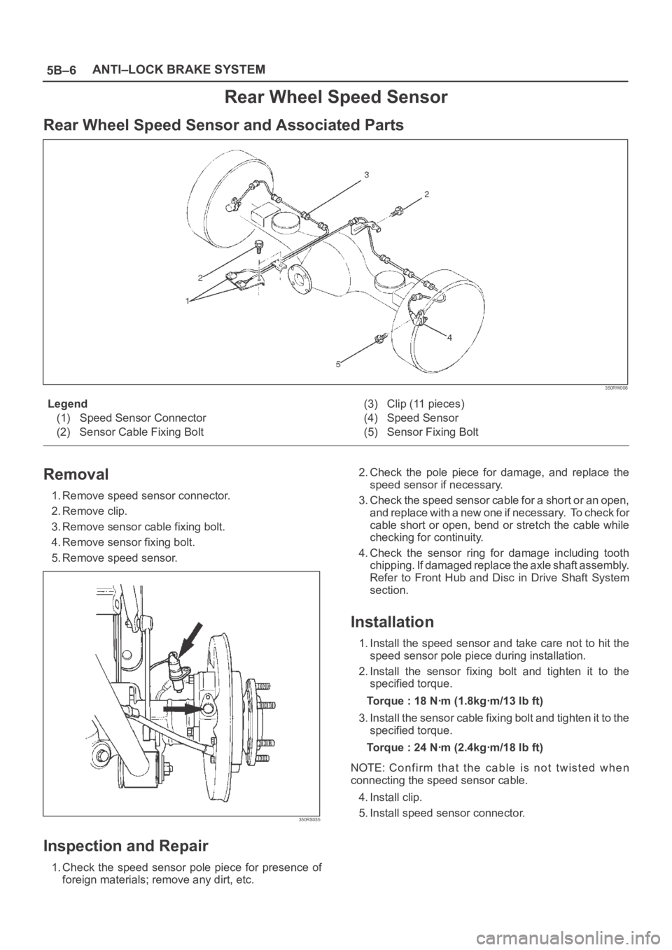
Rear Wheel Speed Sensor
Rear Wheel Speed Sensor and Associated Parts
350RW008
Legend
(1) Speed Sensor Connector
(2) Sensor Cable Fixing Bolt(3) Clip (11 pieces)
(4) Speed Sensor
(5) Sensor Fixing Bolt
Removal
1. Remove speed sensor connector.
2. Remove clip.
3. Remove sensor cable fixing bolt.
4. Remove sensor fixing bolt.
5. Remove speed sensor.
350RS035
Inspection and Repair
1. Check the speed sensor pole piece for presence of
foreign materials; remove any dirt, etc.2. Check the pole piece for damage, and replace the
speed sensor if necessary.
3. Check the speed sensor cable for a short or an open,
and replace with a new one if necessary. To check for
cable short or open, bend or stretch the cable while
checking for continuity.
4. Check the sensor ring for damage including tooth
chipping. If damaged replace the axle shaft assembly.
Refer to Front Hub and Disc in Drive Shaft System
section.
Installation
1. Install the speed sensor and take care not to hit the
speed sensor pole piece during installation.
2. Install the sensor fixing bolt and tighten it to the
specified torque.
Torque : 18 Nꞏm (1.8kgꞏm/13 lb ft)
3. Install the sensor cable fixing bolt and tighten it to the
specified torque.
Torque : 24 Nꞏm (2.4kgꞏm/18 lb ft)
NOTE: Confirm that the cable is not twisted when
connecting the speed sensor cable.
4. Install clip.
5. Install speed sensor connector.
Page 4539 of 6000

6A–43
ENGINE MECHANICAL
6. Remove oil pump assembly.
Refer to removal procedure for Oil Pump in this
manual.
7. Remove cylinder body side bolts.
8. Remove oil gallery.
9. Remove flywheel.
10. Remove rear oil seal retainer.
Refer to removal procedure for Rear Oil Seal in this
manual.
11. Remove connecting rod caps.
12. Remove crankshaft main bearing caps.
13. Remove crankshaft and main bearings.
Installation
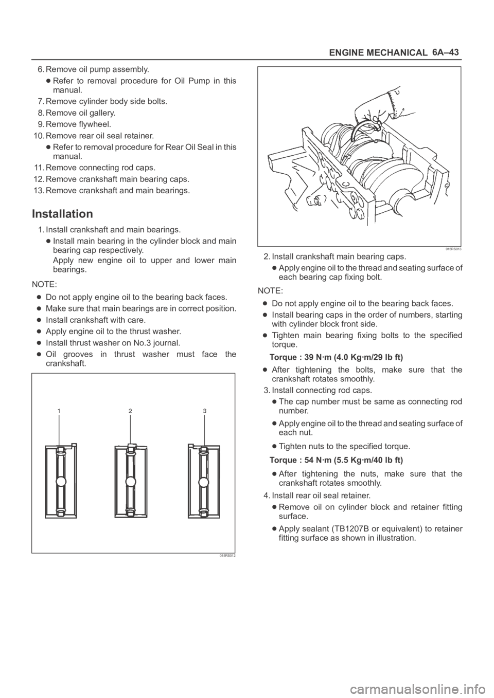
1. Install crankshaft and main bearings.
Install main bearing in the cylinder block and main
bearing cap respectively.
Apply new engine oil to upper and lower main
bearings.
NOTE:
Do not apply engine oil to the bearing back faces.
Make sure that main bearings are in correct position.
Install crankshaft with care.
Apply engine oil to the thrust washer.
Install thrust washer on No.3 journal.
Oil grooves in thrust washer must face the
crankshaft.
015RS012
015RS013
2. Install crankshaft main bearing caps.
Apply engine oil to the thread and seating surface of
each bearing cap fixing bolt.
NOTE:
Do not apply engine oil to the bearing back faces.
Install bearing caps in the order of numbers, starting
with cylinder block front side.
Tighten main bearing fixing bolts to the specified
torque.
Torque : 39 Nꞏm (4.0 Kgꞏm/29 lb ft)
After tightening the bolts, make sure that the
crankshaft rotates smoothly.
3. Install connecting rod caps.
The cap number must be same as connecting rod
number.
Apply engine oil to the thread and seating surface of
each nut.
Tighten nuts to the specified torque.
Torque : 54 Nꞏm (5.5 Kgꞏm/40 lb ft)
After tightening the nuts, make sure that the
crankshaft rotates smoothly.
4. Install rear oil seal retainer.
Remove oil on cylinder block and retainer fitting
surface.
Apply sealant (TB1207B or equivalent) to retainer
fitting surface as shown in illustration.
Page 4540 of 6000

6A–44
ENGINE MECHANICAL
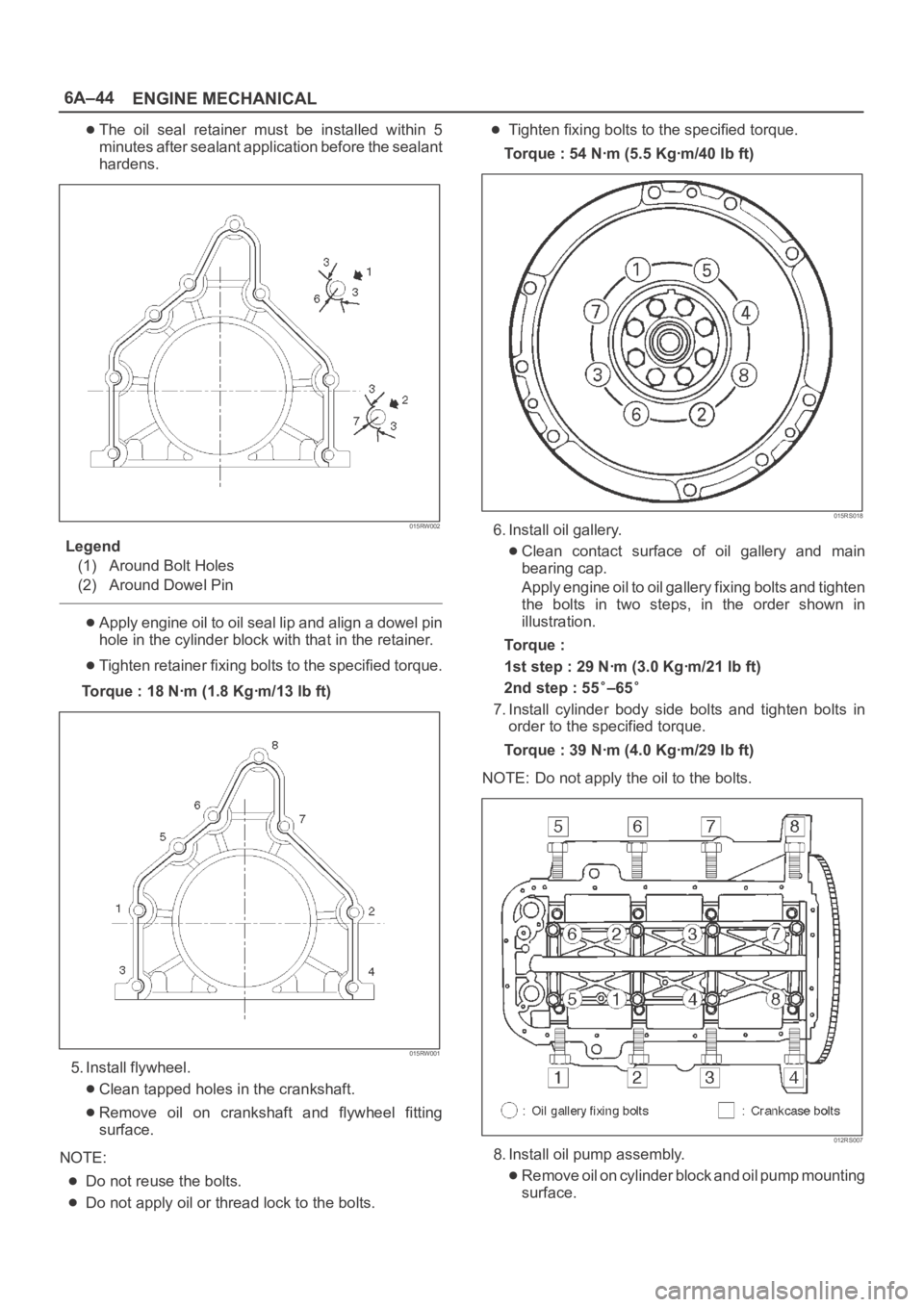
The oil seal retainer must be installed within 5
minutes after sealant application before the sealant
hardens.
015RW002
Legend
(1) Around Bolt Holes
(2) Around Dowel Pin
Apply engine oil to oil seal lip and align a dowel pin
hole in the cylinder block with that in the retainer.
Tighten retainer fixing bolts to the specified torque.
Torque : 18 Nꞏm (1.8 Kgꞏm/13 lb ft)
015RW001
5. Install flywheel.
Clean tapped holes in the crankshaft.
Remove oil on crankshaft and flywheel fitting
surface.
NOTE:
Do not reuse the bolts.
Do not apply oil or thread lock to the bolts.
Tighten fixing bolts to the specified torque.
Torque : 54 Nꞏm (5.5 Kgꞏm/40 lb ft)
015RS018
6. Install oil gallery.
Clean contact surface of oil gallery and main
bearing cap.
Apply engine oil to oil gallery fixing bolts and tighten
the bolts in two steps, in the order shown in
illustration.
To r q u e :
1st step : 29 Nꞏm (3.0 Kgꞏm/21 lb ft)
2nd step : 55
–65
7. Install cylinder body side bolts and tighten bolts in
order to the specified torque.
Torque : 39 Nꞏm (4.0 Kgꞏm/29 lb ft)
NOTE: Do not apply the oil to the bolts.
012RS007
8. Install oil pump assembly.
Remove oil on cylinder block and oil pump mounting
surface.