1998 OPEL FRONTERA wheel torque
[x] Cancel search: wheel torquePage 1074 of 6000
6C–7
ENGINE FUEL
Fuel Pump Relay
General Description
In order to control the FP operation, the FP relay is
provided. When the starter switch is turned to “ON”
position, the FP relay operates the FP for 2 seconds.When it is turned to “START” position, the Power Train
Control Module (PCM) receives the reference pulse from
the Ignition Control Module and it operates the relay,
again causing the FP to feed fuel.
Fuel Tank
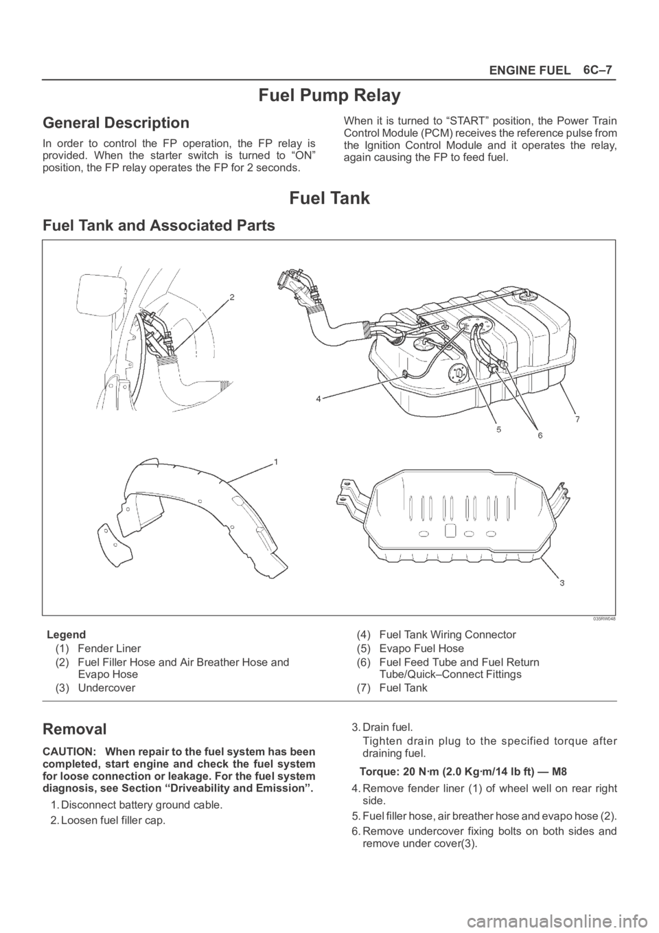
Fuel Tank and Associated Parts
035RW048
Legend
(1) Fender Liner
(2) Fuel Filler Hose and Air Breather Hose and
Evapo Hose
(3) Undercover(4) Fuel Tank Wiring Connector
(5) Evapo Fuel Hose
(6) Fuel Feed Tube and Fuel Return
Tube/Quick–Connect Fittings
(7) Fuel Tank
Removal
CAUTION: When repair to the fuel system has been
completed, start engine and check the fuel system
for loose connection or leakage. For the fuel system
diagnosis, see Section “Driveability and Emission”.
1. Disconnect battery ground cable.
2. Loosen fuel filler cap.3. Drain fuel.
Tighten drain plug to the specified torque after
draining fuel.
Torque: 20 Nꞏm (2.0 Kgꞏm/14 lb ft) — M8
4. Remove fender liner (1) of wheel well on rear right
side.
5. Fuel filler hose, air breather hose and evapo hose (2).
6. Remove undercover fixing bolts on both sides and
remove under cover(3).
Page 1075 of 6000
6C–8
ENGINE FUEL
7. Disconnect two fuel tank wiring connectors(4) on
front right side of tank.
8. Disconnect evapo fuel hose(5).
9. Disconnect fuel feed tube and fuel return tube(6).
NOTE: Handling of the fuel tube, be sure to refer “Fuel
Tube/Quick–Connect Fittings” in this section.
10. Remove fuel tank fixing bolts on both sides and
remove fuel tank(7).
Installation
1. Install fuel tank(7).
Place a flange on right side of tank on the bracket.
Install a flange on left side on the bracket from the
bottom, and tighten bolts to the specified torque.
Torque: 36 Nꞏm (3.7 Kgꞏm/27 lb ft)
2. Connect fuel feed tube and fuel return tube(6).
3. Connect evapo fuel hose(5).
4. Connect fuel tank wiring connector(4).
5. Install undercover(3).
6. Connect fuel filler hose, air breather hose and evapo
hose(2).
7. Install fender liner(1).
Mount fender liner to the wheel well.
Fill the tank with fuel and tighten fuel filler cap.
Connect battery ground cable.
Fuel Tube / Quick – Connect Fittings
Precautions
Lighting of Fires Prohibited.
Keep flames away from your work area to prevent the
inflammable from catching fire.
Disconnect the battery negative cable to prevent
shorting during work.
When welding or conducting other heat-generating
work on other parts, be sure to provide pretreatment
to protect the piping system from thermal damage or
spattering.
Cautions During Work
Do not expose the assembly to battery electrolyte or do
not wipe the assembly with a cloth used to wipe off spilt
battery electorolyte.
The piping wet with battery electrolyte cannot be used.
Be careful not to give a bending or twisting force to the
piping during the work. If deformed, replace with a new
piping.
Removal
1. Open the fuel cap to relieve the fuel pressure in the
tank.
If the fuel quick-connect fittings are dusty, clean with
an air blower, etc. and then remove it.
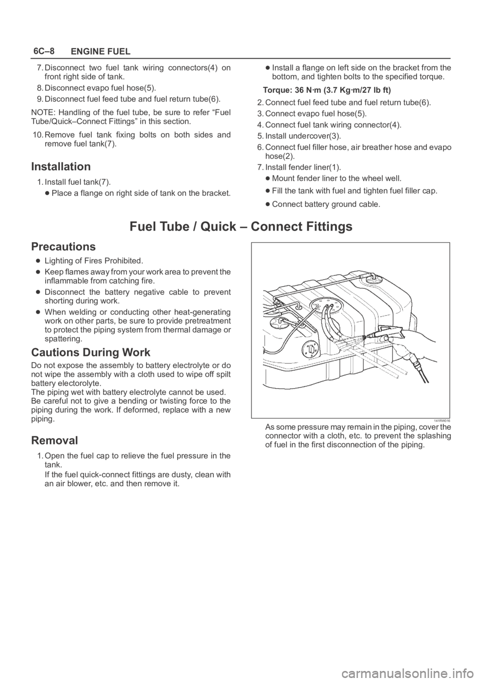
141RW016As some pressure may remain in the piping, cover the
connector with a cloth, etc. to prevent the splashing
of fuel in the first disconnection of the piping.
Page 1806 of 6000
ENGINE MECHANICAL 6A – 73
INSTALLATION
1. Install relief valve (if it was removed).
Torque: 30 Nꞏm (3.1 kgꞏm / 22 lb ft)
2. Insert O-ring to strainer, install strainer and tighten
to specified torque.
Torque: 20 Nꞏm (2.0 kgꞏm / 14.5 lb ft)
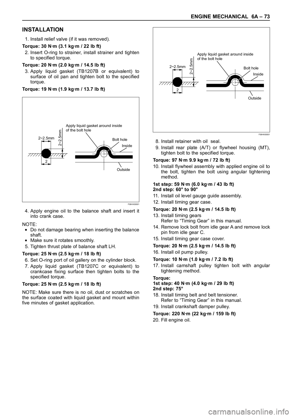
3. Apply liquid gasket (TB1207B or equivalent) to
surface of oil pan and tighten bolt to the specified
torque.
Torque: 19 Nꞏm (1.9 kgꞏm / 13.7 lb ft)
4. Apply engine oil to the balance shaft and insert it
into crank case.
NOTE:
Do not damage bearing when inserting the balance
shaft.
Make sure it rotates smoothly.
5. Tighten thrust plate of balance shaft LH.
Torque: 25 Nꞏm (2.5 kgꞏm / 18 lb ft)
6. Set O-ring port of oil gallery on the cylinder block.
7. Apply liquid gasket (TB1207C or equivalent) to
crankcase fixing surface then tighten bolts to the
specified torque.
Torque: 25 Nꞏm (2.5 kgꞏm / 18 lb ft)
NOTE: Make sure there is no oil, dust or scratches on
the surface coated with liquid gasket and mount within
five minutes of gasket application.8. Install retainer with oil seal.
9. Install rear plate (A/T) or flywheel housing (MT),
tighten bolt to the specified torque.
Torque: 97 Nꞏm 9.9 kgꞏm / 72 lb ft)
10. Install flywheel assembly with applied engine oil to
the bolt, tighten the bolt using angular tightening
method.
1st step: 59 Nꞏm (6.0 kgꞏm / 43 lb ft)
2nd step: 60° to 90°
11. Install oil level gauge guide assembly.
12. Install timing gear case.
Torque: 20 Nꞏm (2.5 kgꞏm / 14.5 lb ft)
13. Install timing gears
Refer to “Timing Gear” in this manual.
14. Remove lock bolt from idle gear A and remove lock
pin from idle gear C.
15. Install timing gear case cover.
Torque: 20 Nꞏm (2.5 kgꞏm / 14.5 lb ft)
16. Install oil pump pulley.
Torque: 10 Nꞏm (1.0 kgꞏm / 7.2 lb ft)
17. Install camshaft pulley tighten bolt with angular
tightening method.
To r q u e :
1st step: 40 Nꞏm (4.0 kgꞏm / 29 lb ft)
2nd step: 75°
18. Install timing belt and belt tensioner.
Refer to “Timing Gear” in this manual.
19. Install crankshaft damper pulley.
Torque: 220 Nꞏm (22 kgꞏm / 159 lb ft)
20. Fill engine oil.
2
2~2.5mm
2~2.5mm
Apply liquid gasket around inside
of the bolt hole
Bolt hole
Inside
Outside
F06HX00001
2
2~2.5mm
2~2.5mm
Apply liquid gasket around inside
of the bolt hole
Bolt hole
Inside
Outside
F06HX00001
Page 1814 of 6000
ENGINE MECHANICAL 6A – 81
8. Cylinder Block Rear Plate (A/T)
Align the rear plate with the cylinder block dowel
pins.
Tighten the rear plate to the specified torque.
Torque: 97 Nꞏm (9.9 kgꞏm/72 lb ft)
9. Flywheel housing (M/T)
Align the flywheel housing with the cylinder block
dowel pins.
Tighten the bolt to the specified torque.
Torque: 97 Nꞏm (9.9 kgꞏm/72 lb ft)
10. Flywheel
1) Thoroughly clean and remove the oil from the
threads of crankshaft and flywheel fixing
surface.
2) Mount the flywheel on the crankshaft and then
install the washer.
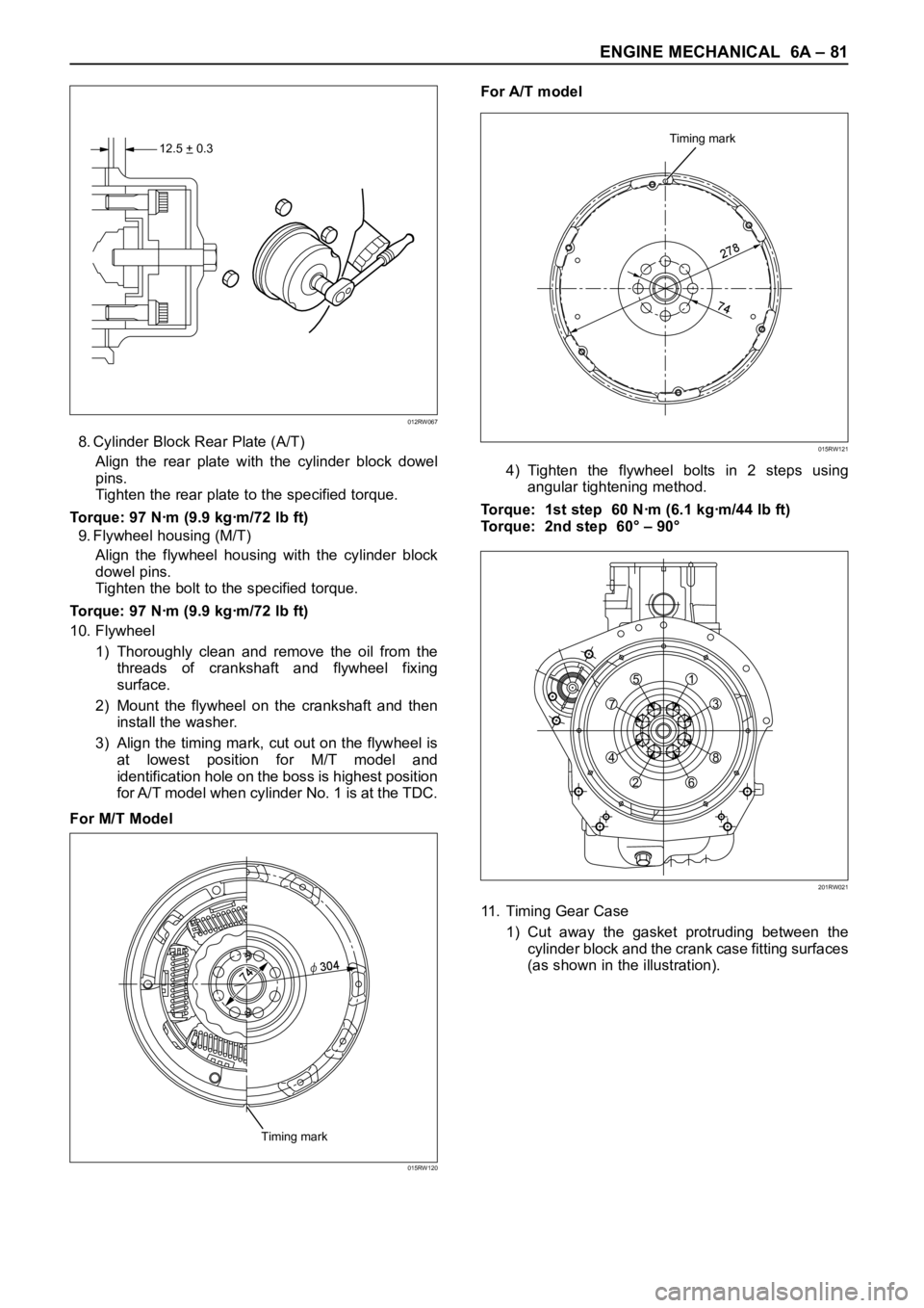
3) Align the timing mark, cut out on the flywheel is
at lowest position for M/T model and
identification hole on the boss is highest position
for A/T model when cylinder No. 1 is at the TDC.
For M/T ModelFor A/T model
4) Tighten the flywheel bolts in 2 steps using
angular tightening method.
Torque: 1st step 60 Nꞏm (6.1 kgꞏm/44 lb ft)
Torque: 2nd step 60° – 90°
11. Timing Gear Case
1) Cut away the gasket protruding between the
cylinder block and the crank case fitting surfaces
(as shown in the illustration).
12.5 + 0.3–
012RW067
Timing mark
2
78
74
015RW121
Timing mark
7
4φ
304
015RW120
751
3
8
6 2 4
201RW021
Page 1830 of 6000

ENGINE MECHANICAL 6A – 97
11. Use the special tool to install the crankshaft front oil
seal to timing gear case.
Front Oil Seal Installer: 5-8840-2061-0
1) Check fit-of the oil seal and gear case cover at
the front end.
Standard: 0.5 – 2.5 mm (0.0197 – 0.0984 in)
NOTE: Apply engine oil to oil seal lip before installation
of the seal.
12. Install the oil pan assembly to original position and
tighten to specified torque.
Torque: 22 Nꞏm (2.2 kgꞏm/15.9 lb ft)
13. Crankshaft Rear Oil Seal
1) Tighten the adapter to the crankshaft rear end
with 2 bolts.
2) Insert the oil seal into the adapter.
3) Insert the sleeve into the adapter and tighten it
with a bolt (M12 x 1.75L = 70) until the adapter
hits the sleeve.
4) Remove the adapter and the sleeve.
5) With the seal pressed in, check the dimension of
the oil seal outside end and crankshaft end.
Standard Dimension = 12.5 ± 0.3 mm
Oil Seal Installer: 5-8840-2359-014. Cylinder Block Rear Plate (A/T Model)
1) Tighten the cylinder block rear plate fixing bolts
to the specified torque.
Torque: 97 Nꞏm (9.9 kgꞏm/72 lb ft)
15. Flywheel Housing (M/T Model)
1) Install flywheel housing aligned with the dowel
pin on the cylinder block.
2) Tighten the flywheel housing fixing bolts to the
specified torque.
Torque: 97 Nꞏm (9.9 kgꞏm/72 lb ft)
16. Flywheel
1) Refer to “Crankshaft” in this manual.
17. Cylinder Head Assembly
1) Refer to “Cylinder Head” in this manual.
015RW074
12.5 + 0.3–
012RW067
Page 1831 of 6000
6A – 98 ENGINE MECHANICAL
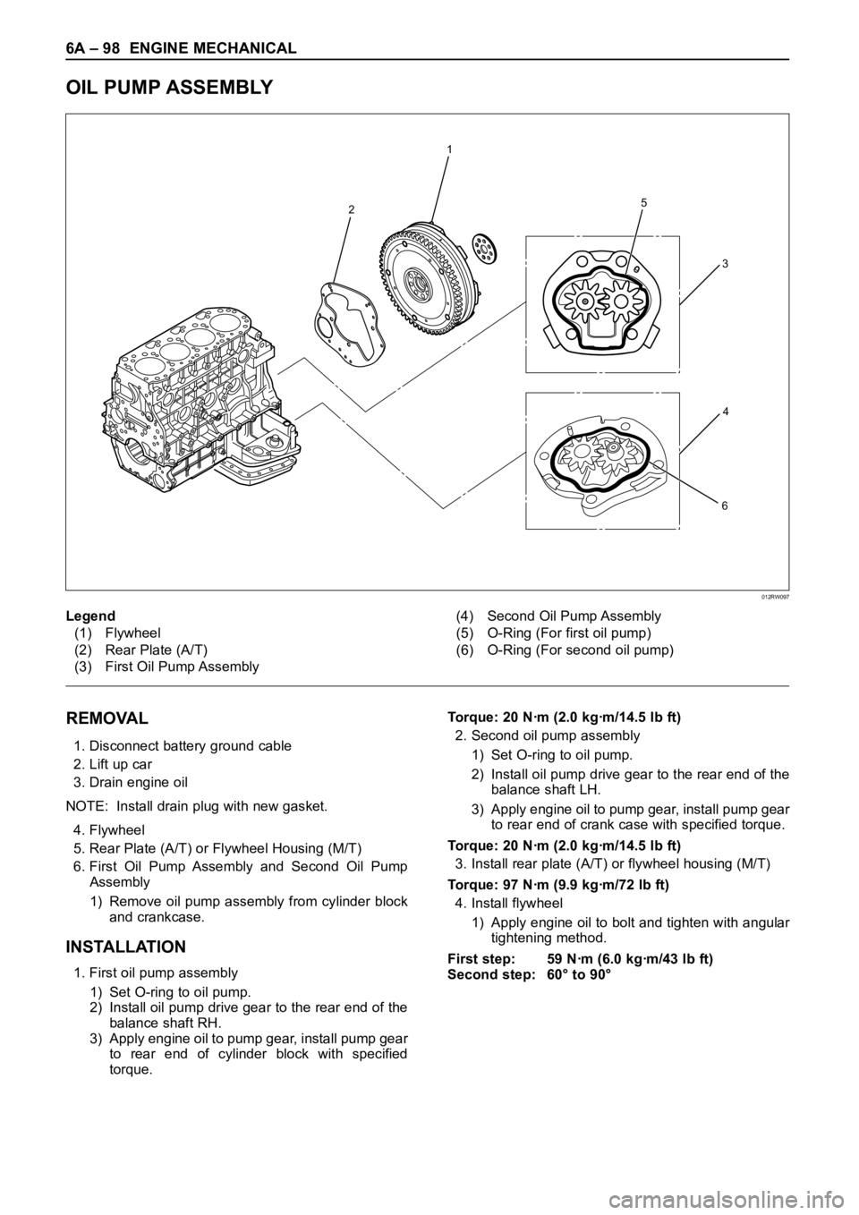
OIL PUMP ASSEMBLY
2
1
5
6
3
4
012RW097
Legend
(1) Flywheel
(2) Rear Plate (A/T)
(3) First Oil Pump Assembly(4) Second Oil Pump Assembly
(5) O-Ring (For first oil pump)
(6) O-Ring (For second oil pump)
REMOVAL
1. Disconnect battery ground cable
2. Lift up car
3. Drain engine oil
NOTE: Install drain plug with new gasket.
4. Flywheel
5. Rear Plate (A/T) or Flywheel Housing (M/T)
6. First Oil Pump Assembly and Second Oil Pump
Assembly
1) Remove oil pump assembly from cylinder block
and crankcase.
INSTALLATION
1. First oil pump assembly
1) Set O-ring to oil pump.
2) Install oil pump drive gear to the rear end of the
balance shaft RH.
3) Apply engine oil to pump gear, install pump gear
to rear end of cylinder block with specified
torque.Torque: 20 Nꞏm (2.0 kgꞏm/14.5 lb ft)
2. Second oil pump assembly
1) Set O-ring to oil pump.
2) Install oil pump drive gear to the rear end of the
balance shaft LH.
3) Apply engine oil to pump gear, install pump gear
to rear end of crank case with specified torque.
Torque: 20 Nꞏm (2.0 kgꞏm/14.5 lb ft)
3. Install rear plate (A/T) or flywheel housing (M/T)
Torque: 97 Nꞏm (9.9 kgꞏm/72 lb ft)
4. Install flywheel
1) Apply engine oil to bolt and tighten with angular
tightening method.
First step: 59 Nꞏm (6.0 kgꞏm/43 lb ft)
Second step: 60° to 90°
Page 2136 of 6000
ENGINE LUBRICATION 6G – 5
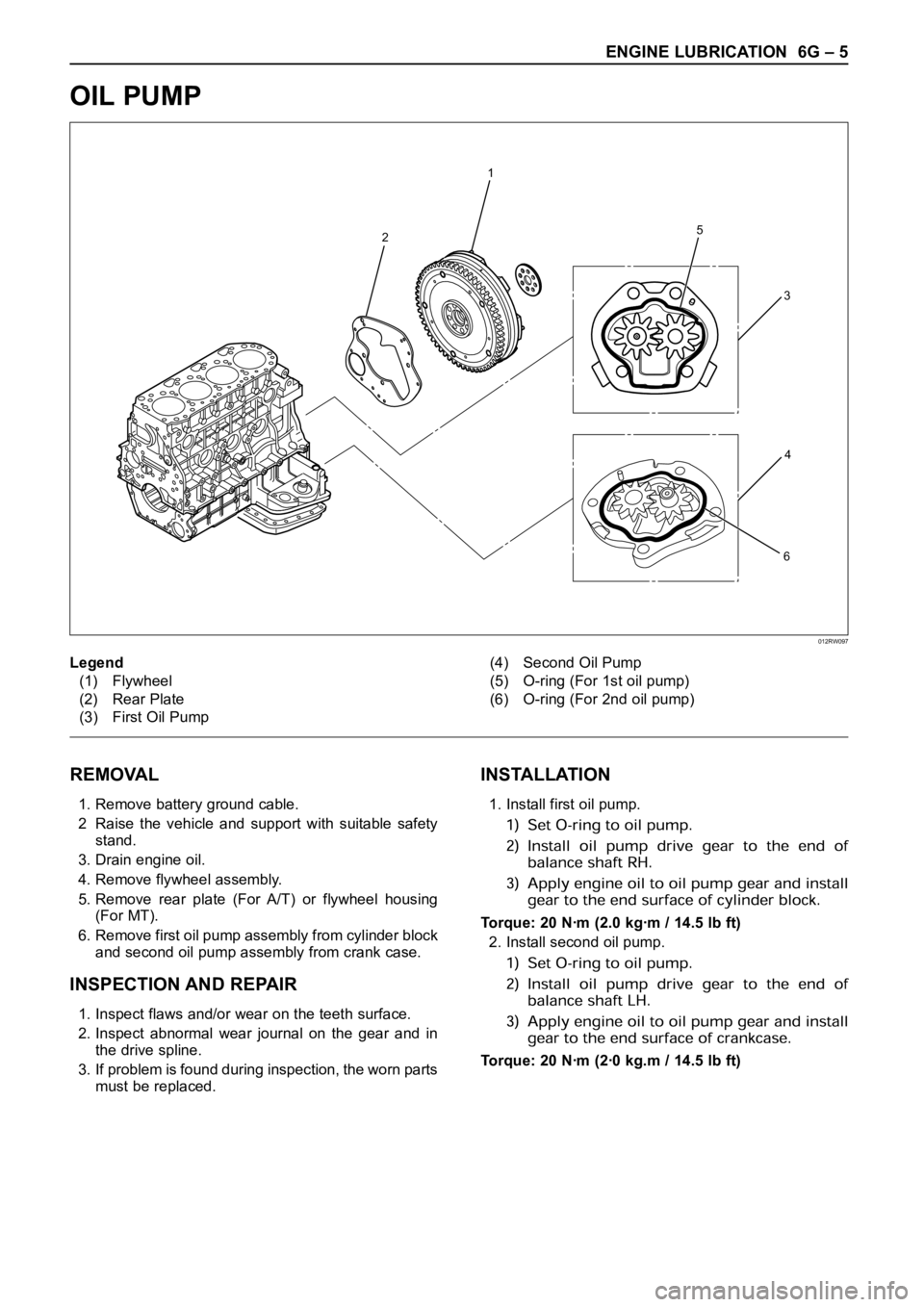
OIL PUMP
REMOVAL
1. Remove battery ground cable.
2 Raise the vehicle and support with suitable safety
stand.
3. Drain engine oil.
4. Remove flywheel assembly.
5. Remove rear plate (For A/T) or flywheel housing
(For MT).
6. Remove first oil pump assembly from cylinder block
and second oil pump assembly from crank case.
INSPECTION AND REPAIR
1. Inspect flaws and/or wear on the teeth surface.
2. Inspect abnormal wear journal on the gear and in
the drive spline.
3. If problem is found during inspection, the worn parts
must be replaced.
INSTALLATION
1. Install first oil pump.
Torque: 20 Nꞏm (2.0 kgꞏm / 14.5 lb ft)
2. Install second oil pump.
Torque: 20 Nꞏm (2ꞏ0 kg.m / 14.5 lb ft)
2
1
5
6
3
4
Legend
(1) Flywheel
(2) Rear Plate
(3) First Oil Pump(4) Second Oil Pump
(5) O-ring (For 1st oil pump)
(6) O-ring (For 2nd oil pump)
012RW097
Page 2157 of 6000
7A–3 AUTOMATIC TRANSMISSION (4L30–E)
Service Precaution
WARNING: IF SO EQUIPPED WITH A
SUPPLEMENTAL RESTRAINT SYSTEM (SRS),
REFER TO THE SRS COMPONENT AND WIRING
LOCATION VIEW IN ORDER TO DETERMINE
WHETHER YOU ARE PERFORMING SERVICE ON OR
NEAR THE SRS COMPONENTS OR THE SRS
WIRING. WHEN YOU ARE PERFORMING SERVICE
ON OR NEAR THE SRS COMPONENTS OR THE SRS
WIRING, REFER TO THE SRS SERVICE
INFORMATION. FAILURE TO FOLLOW WARNINGS
COULD RESULT IN POSSIBLE AIR BAG
DEPLOYMENT, PERSONAL INJURY, OR
OTHERWISE UNNEEDED SRS SYSTEM REPAIRS.CAUTION: Always use the correct fastener in the
proper location. When you replace a fastener, use
ONLY the exact part number for that application.
ISUZU will call out those fasteners that require a
replacement after removal. ISUZU will also call out
the fasteners that require thread lockers or thread
sealant. UNLESS OTHERWISE SPECIFIED, do not
use supplemental coatings (Paints, greases, or other
corrosion inhibitors) on threaded fasteners or
fastener joint interfaces. Generally, such coatings
adversely affect the fastener torque and the joint
clamping force, and may damage the fastener. When
you install fasteners, use the correct tightening
sequence and specifications. Following these
instructions can help you avoid damage to parts and
systems.
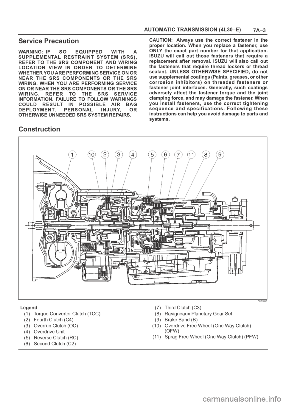
Construction
A07RS001
Legend
(1) Torque Converter Clutch (TCC)
(2) Fourth Clutch (C4)
(3) Overrun Clutch (OC)
(4) Overdrive Unit
(5) Reverse Clutch (RC)
(6) Second Clutch (C2)(7) Third Clutch (C3)
(8) Ravigneaux Planetary Gear Set
(9) Brake Band (B)
(10) Overdrive Free Wheel (One Way Clutch)
(OFW)
(11) Sprag Free Wheel (One Way Clutch) (PFW)