1998 OPEL FRONTERA fuel cap
[x] Cancel search: fuel capPage 4611 of 6000
6C–4
ENGINE FUEL
Fuel Filter
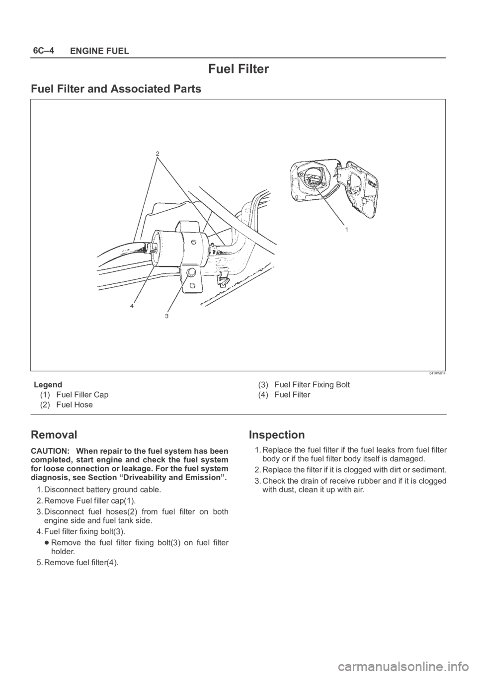
Fuel Filter and Associated Parts
041RW014
Legend
(1) Fuel Filler Cap
(2) Fuel Hose(3) Fuel Filter Fixing Bolt
(4) Fuel Filter
Removal
CAUTION: When repair to the fuel system has been
completed, start engine and check the fuel system
for loose connection or leakage. For the fuel system
diagnosis, see Section “Driveability and Emission”.
1. Disconnect battery ground cable.
2. Remove Fuel filler cap(1).
3. Disconnect fuel hoses(2) from fuel filter on both
engine side and fuel tank side.
4. Fuel filter fixing bolt(3).
Remove the fuel filter fixing bolt(3) on fuel filter
holder.
5. Remove fuel filter(4).
Inspection
1. Replace the fuel filter if the fuel leaks from fuel filter
body or if the fuel filter body itself is damaged.
2. Replace the filter if it is clogged with dirt or sediment.
3. Check the drain of receive rubber and if it is clogged
with dust, clean it up with air.
Page 4612 of 6000
6C–5
ENGINE FUEL
Installation
1. Install the fuel filter in the proper direction.
2. Install fuel filter holder fixing bolt.
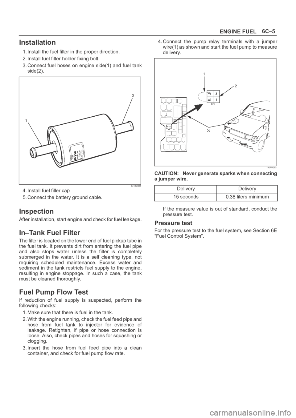
3. Connect fuel hoses on engine side(1) and fuel tank
side(2).
041RW001
4. Install fuel filler cap
5. Connect the battery ground cable.
Inspection
After installation, start engine and check for fuel leakage.
In–Tank Fuel Filter
The filter is located on the lower end of fuel pickup tube in
the fuel tank. It prevents dirt from entering the fuel pipe
and also stops water unless the filter is completely
submerged in the water. It is a self cleaning type, not
requiring scheduled maintenance. Excess water and
sediment in the tank restricts fuel supply to the engine,
resulting in engine stoppage. In such a case, the tank
must be cleaned thoroughly.
Fuel Pump Flow Test
If reduction of fuel supply is suspected, perform the
following checks:
1. Make sure that there is fuel in the tank.
2. With the engine running, check the fuel feed pipe and
hose from fuel tank to injector for evidence of
leakage. Retighten, if pipe or hose connection is
loose. Also, check pipes and hoses for squashing or
clogging.
3. Insert the hose from fuel feed pipe into a clean
container, and check for fuel pump flow rate.4. Connect the pump relay terminals with a jumper
wire(1) as shown and start the fuel pump to measure
delivery.
140RW002
CAUTION: Never generate sparks when connecting
a jumper wire.
Delivery
Delivery
15 seconds0.38 liters minimum
If the measure value is out of standard, conduct the
pressure test.
Pressure test
For the pressure test to the fuel system, see Section 6E
“Fuel Control System”.
Page 4613 of 6000
6C–6
ENGINE FUEL
Fuel Pump
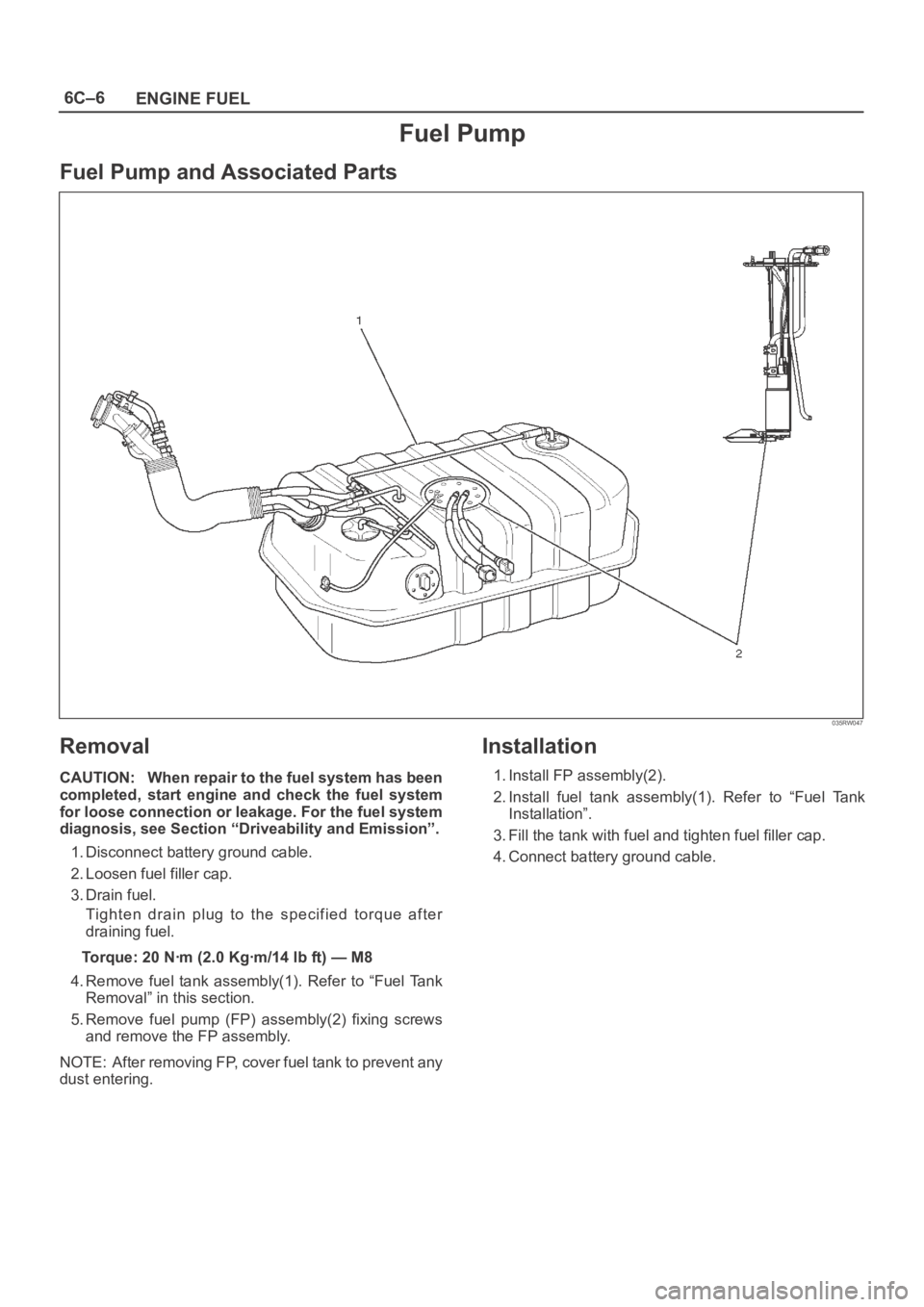
Fuel Pump and Associated Parts
035RW047
Removal
CAUTION: When repair to the fuel system has been
completed, start engine and check the fuel system
for loose connection or leakage. For the fuel system
diagnosis, see Section “Driveability and Emission”.
1. Disconnect battery ground cable.
2. Loosen fuel filler cap.
3. Drain fuel.
Tighten drain plug to the specified torque after
draining fuel.
Torque: 20 Nꞏm (2.0 Kgꞏm/14 lb ft) — M8
4. Remove fuel tank assembly(1). Refer to “Fuel Tank
Removal” in this section.
5. Remove fuel pump (FP) assembly(2) fixing screws
and remove the FP assembly.
NOTE: After removing FP, cover fuel tank to prevent any
dust entering.
Installation
1. Install FP assembly(2).
2. Install fuel tank assembly(1). Refer to “Fuel Tank
Installation”.
3. Fill the tank with fuel and tighten fuel filler cap.
4. Connect battery ground cable.
Page 4614 of 6000
6C–7
ENGINE FUEL
Fuel Pump Relay
General Description
In order to control the FP operation, the FP relay is
provided. When the starter switch is turned to “ON”
position, the FP relay operates the FP for 2 seconds.When it is turned to “START” position, the Power Train
Control Module (PCM) receives the reference pulse from
the Ignition Control Module and it operates the relay,
again causing the FP to feed fuel.
Fuel Tank
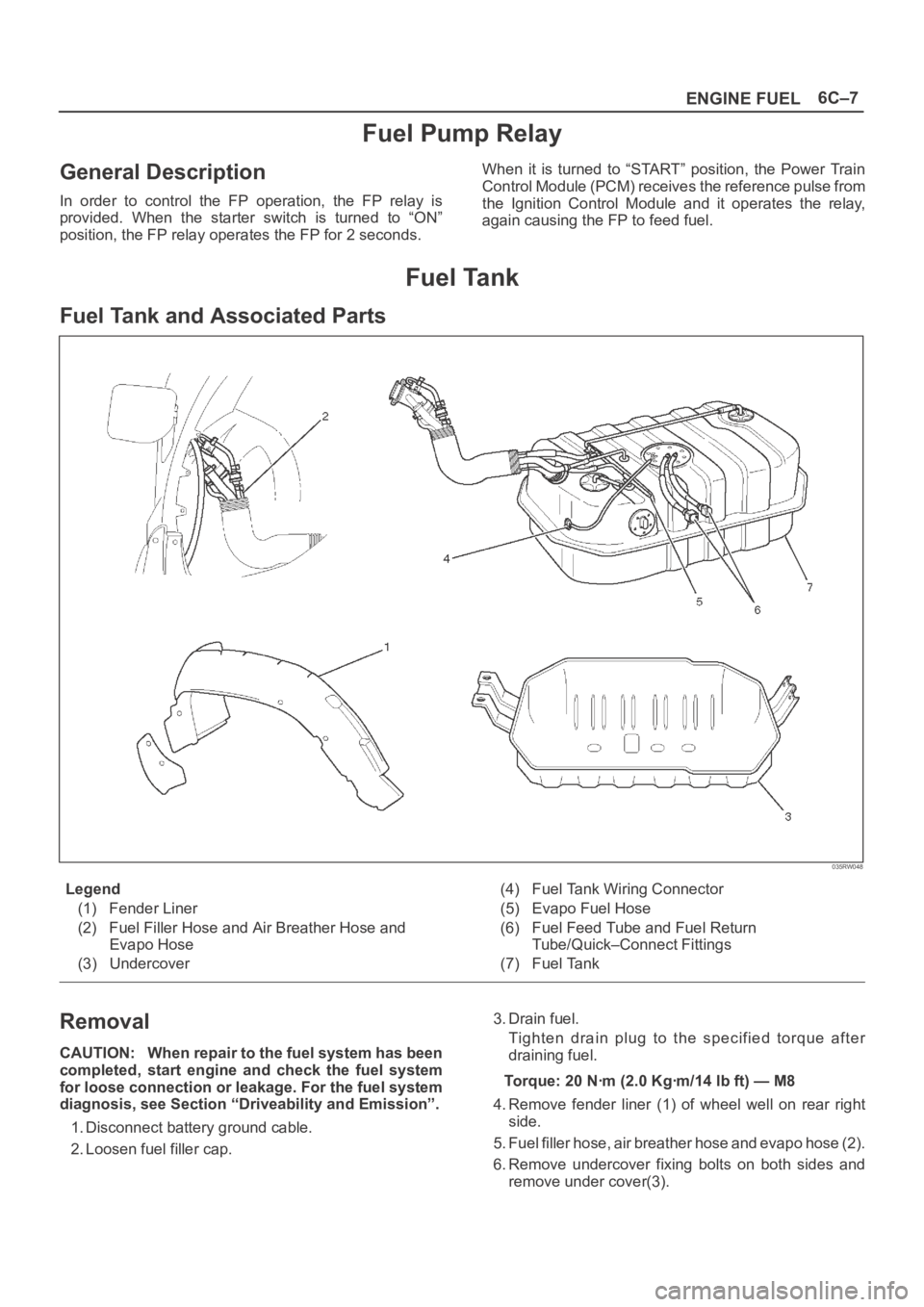
Fuel Tank and Associated Parts
035RW048
Legend
(1) Fender Liner
(2) Fuel Filler Hose and Air Breather Hose and
Evapo Hose
(3) Undercover(4) Fuel Tank Wiring Connector
(5) Evapo Fuel Hose
(6) Fuel Feed Tube and Fuel Return
Tube/Quick–Connect Fittings
(7) Fuel Tank
Removal
CAUTION: When repair to the fuel system has been
completed, start engine and check the fuel system
for loose connection or leakage. For the fuel system
diagnosis, see Section “Driveability and Emission”.
1. Disconnect battery ground cable.
2. Loosen fuel filler cap.3. Drain fuel.
Tighten drain plug to the specified torque after
draining fuel.
Torque: 20 Nꞏm (2.0 Kgꞏm/14 lb ft) — M8
4. Remove fender liner (1) of wheel well on rear right
side.
5. Fuel filler hose, air breather hose and evapo hose (2).
6. Remove undercover fixing bolts on both sides and
remove under cover(3).
Page 4615 of 6000
6C–8
ENGINE FUEL
7. Disconnect two fuel tank wiring connectors(4) on
front right side of tank.
8. Disconnect evapo fuel hose(5).
9. Disconnect fuel feed tube and fuel return tube(6).
NOTE: Handling of the fuel tube, be sure to refer “Fuel
Tube/Quick–Connect Fittings” in this section.
10. Remove fuel tank fixing bolts on both sides and
remove fuel tank(7).
Installation
1. Install fuel tank(7).
Place a flange on right side of tank on the bracket.
Install a flange on left side on the bracket from the
bottom, and tighten bolts to the specified torque.
Torque: 36 Nꞏm (3.7 Kgꞏm/27 lb ft)
2. Connect fuel feed tube and fuel return tube(6).
3. Connect evapo fuel hose(5).
4. Connect fuel tank wiring connector(4).
5. Install undercover(3).
6. Connect fuel filler hose, air breather hose and evapo
hose(2).
7. Install fender liner(1).
Mount fender liner to the wheel well.
Fill the tank with fuel and tighten fuel filler cap.
Connect battery ground cable.
Fuel Tube / Quick – Connect Fittings
Precautions
Lighting of Fires Prohibited.
Keep flames away from your work area to prevent the
inflammable from catching fire.
Disconnect the battery negative cable to prevent
shorting during work.
When welding or conducting other heat-generating
work on other parts, be sure to provide pretreatment
to protect the piping system from thermal damage or
spattering.
Cautions During Work
Do not expose the assembly to battery electrolyte or do
not wipe the assembly with a cloth used to wipe off spilt
battery electorolyte.
The piping wet with battery electrolyte cannot be used.
Be careful not to give a bending or twisting force to the
piping during the work. If deformed, replace with a new
piping.
Removal
1. Open the fuel cap to relieve the fuel pressure in the
tank.
If the fuel quick-connect fittings are dusty, clean with
an air blower, etc. and then remove it.
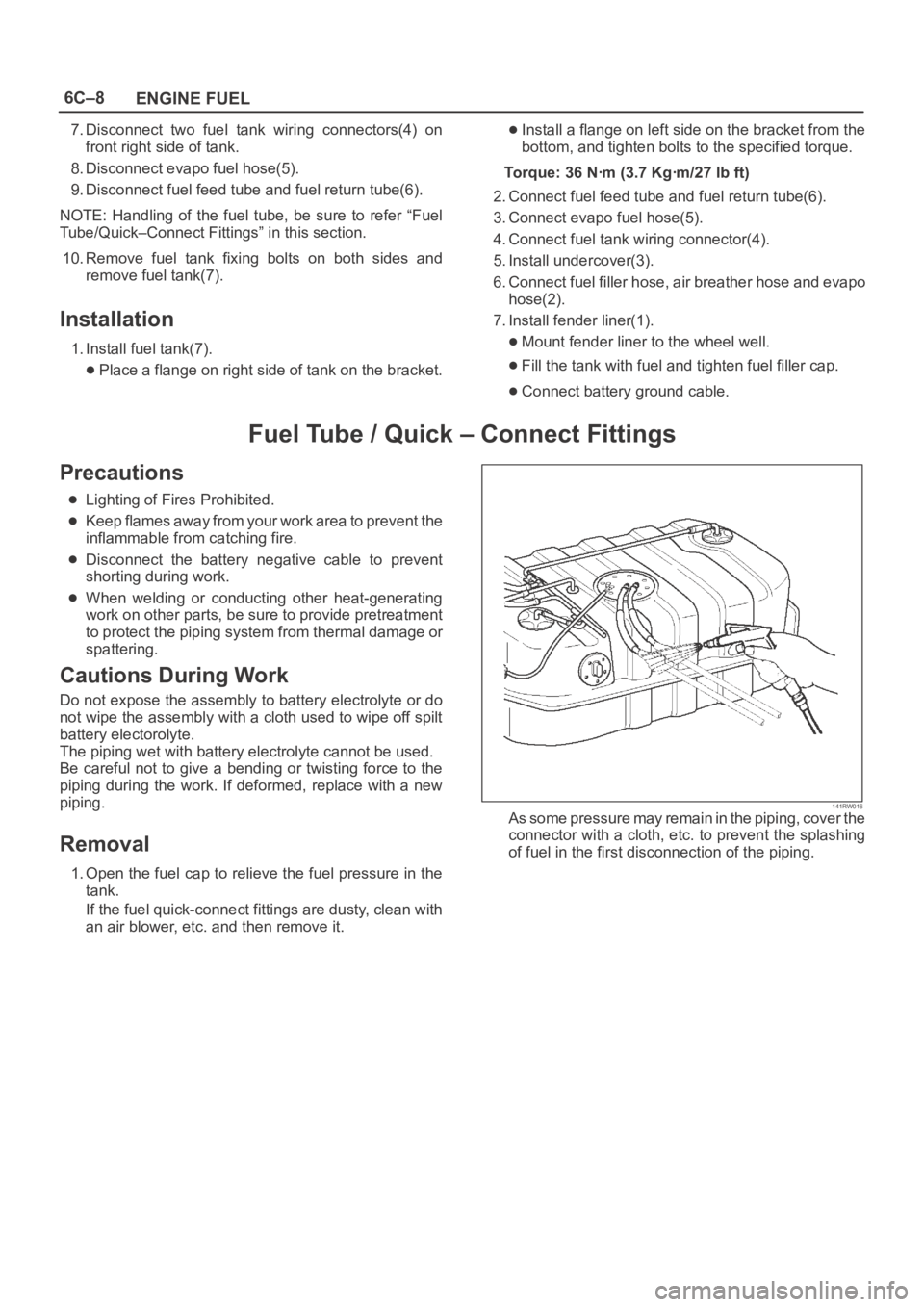
141RW016As some pressure may remain in the piping, cover the
connector with a cloth, etc. to prevent the splashing
of fuel in the first disconnection of the piping.
Page 4618 of 6000
6C–11
ENGINE FUEL
Fuel Gauge Unit
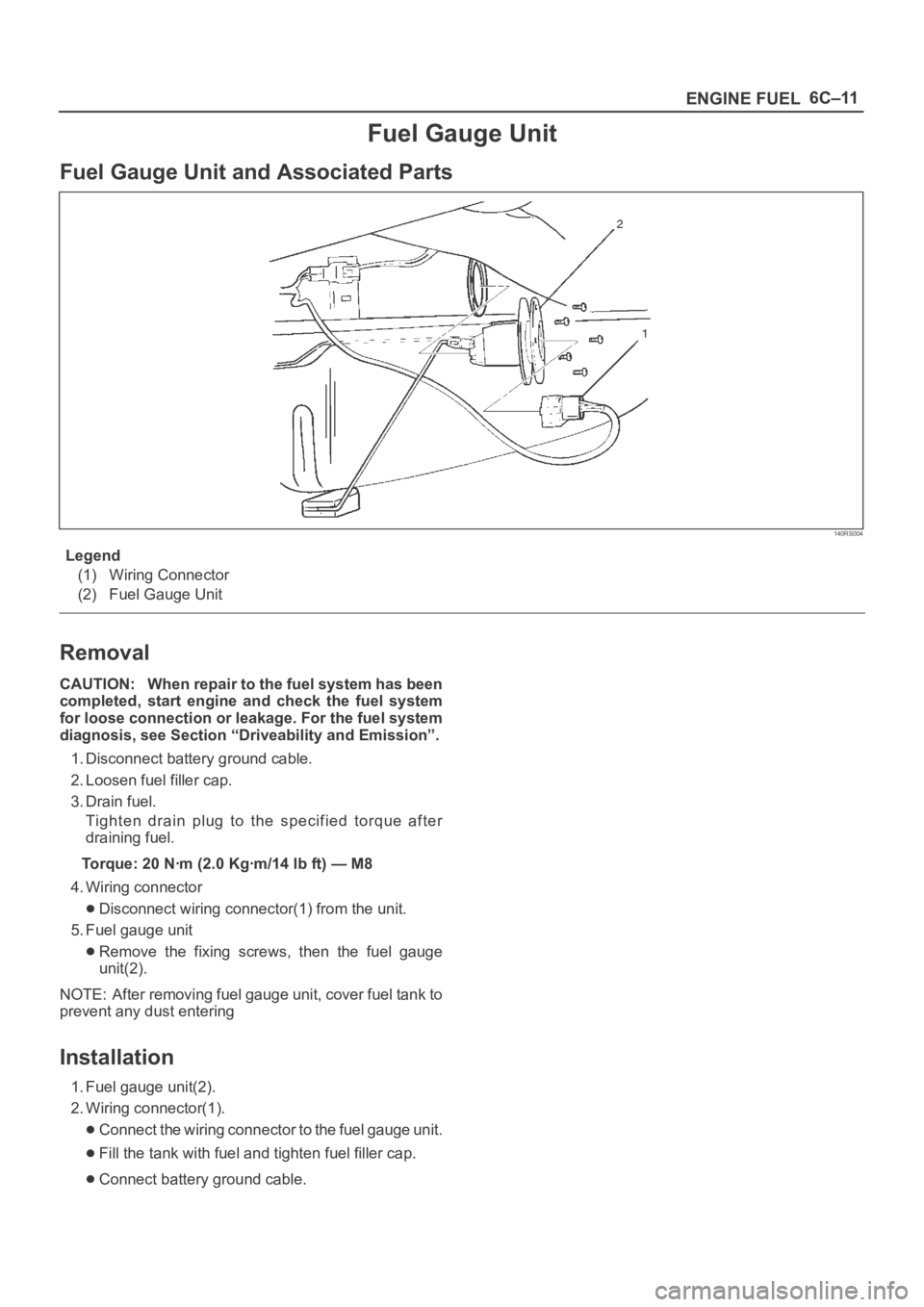
Fuel Gauge Unit and Associated Parts
140RS004
Legend
(1) Wiring Connector
(2) Fuel Gauge Unit
Removal
CAUTION: When repair to the fuel system has been
completed, start engine and check the fuel system
for loose connection or leakage. For the fuel system
diagnosis, see Section “Driveability and Emission”.
1. Disconnect battery ground cable.
2. Loosen fuel filler cap.
3. Drain fuel.
Tighten drain plug to the specified torque after
draining fuel.
Torque: 20 Nꞏm (2.0 Kgꞏm/14 lb ft) — M8
4. Wiring connector
Disconnect wiring connector(1) from the unit.
5. Fuel gauge unit
Remove the fixing screws, then the fuel gauge
unit(2).
NOTE: After removing fuel gauge unit, cover fuel tank to
prevent any dust entering
Installation
1. Fuel gauge unit(2).
2. Wiring connector(1).
Connect the wiring connector to the fuel gauge unit.
Fill the tank with fuel and tighten fuel filler cap.
Connect battery ground cable.
Page 4619 of 6000
6C–12
ENGINE FUEL
Fuel Filler Cap
General Description
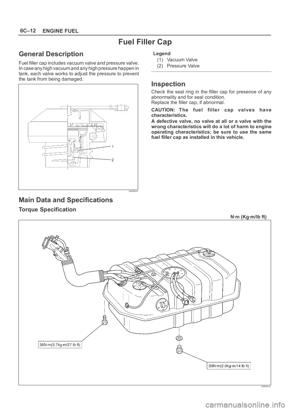
Fuel filler cap includes vacuum valve and pressure valve.
In case any high vacuum and any high pressure happen in
tank, each valve works to adjust the pressure to prevent
the tank from being damaged.
140RW021
Legend
(1) Vacuum Valve
(2) Pressure Valve
Inspection
Check the seal ring in the filler cap for presence of any
abnormality and for seal condition.
Replace the filler cap, if abnormal.
CAUTION: The fuel filler cap valves have
characteristics.
A defective valve, no valve at all or a valve with the
wrong characteristics will do a lot of harm to engine
operating characteristics; be sure to use the same
fuel filler cap as installed in this vehicle.
Main Data and Specifications
Torque Specification
Nꞏm (Kgꞏm/lb ft)
035RW141
Page 4660 of 6000
6E–3 ENGINE DRIVEABILITY AND EMISSIONS
Diagnostic Trouble Code (DTC) P0351
Ignition 1 Control Circuit 6E–206. . . . . . . . . . . . . . . . .
Diagnostic Trouble Code (DTC) P0352
Ignition 2 Control Circuit 6E–209. . . . . . . . . . . . . . . . .
Diagnostic Trouble Code (DTC) P0353
Ignition 3 Control Circuit 6E–212. . . . . . . . . . . . . . . . .
Diagnostic Trouble Code (DTC) P0354
Ignition 4 Control Circuit 6E–215. . . . . . . . . . . . . . . . .
Diagnostic Trouble Code (DTC) P0355
Ignition 5 Control Circuit 6E–218. . . . . . . . . . . . . . . . .
Diagnostic Trouble Code (DTC) P0356
Ignition 6 Control Circuit 6E–221. . . . . . . . . . . . . . . . .
Diagnostic Trouble Code (DTC) P0402
EGR Pintle Crank Error 6E–224. . . . . . . . . . . . . . . . . .
Diagnostic Trouble Code (DTC) P0404
EGR Open Stuck 6E–226. . . . . . . . . . . . . . . . . . . . . . .
Diagnostic Trouble Code (DTC) P0405
EGR Low Voltage 6E–228. . . . . . . . . . . . . . . . . . . . . . .
Diagnostic Trouble Code (DTC) P0406
EGR High Voltage 6E–231. . . . . . . . . . . . . . . . . . . . . .
Diagnostic Trouble Code (DTC) P0502
VSS Circuit Low Input 6E–234. . . . . . . . . . . . . . . . . . .
Diagnostic Trouble Code (DTC) P0562
System Voltage Low 6E–237. . . . . . . . . . . . . . . . . . . .
Diagnostic Trouble Code (DTC) P0563
System Voltage High 6E–239. . . . . . . . . . . . . . . . . . . .
Diagnostic Trouble Code (DTC) P0601
PCM Memory 6E–240. . . . . . . . . . . . . . . . . . . . . . . . . .
Diagnostic Trouble Code (DTC) P1154
HO2S Circuit Transition Time Ratio Bank 2
Sensor 1 6E–241. . . . . . . . . . . . . . . . . . . . . . . . . . . . . .
Diagnostic Trouble Code (DTC) P1171
Fuel System Lean During Acceleration 6E–245. . . .
Diagnostic Trouble Code (DTC) P1380
ABS Rough Road ABS System Fault 6E–248. . . . . .
Diagnostic Trouble Code (DTC) P1404
EGR Closed Stuck 6E–249. . . . . . . . . . . . . . . . . . . . . .
Diagnostic Trouble Code (DTC) P1508
IAC System Low RPM 6E–251. . . . . . . . . . . . . . . . . . .
Diagnostic Trouble Code (DTC) P1509
IAC System High RPM 6E–254. . . . . . . . . . . . . . . . . .
Diagnostic Trouble Code (DTC) P1618
Serial Peripheral Interface (SPI) PCM
Interprocessor Communication Error 6E–257. . . . . .
Diagnostic Trouble Code (DTC) P1625
PCM Unexpected Reset 6E–258. . . . . . . . . . . . . . . . .
Diagnostic Trouble Code (DTC) P1640
Driver-1-Input High Voltage 6E–259. . . . . . . . . . . . . .
Symptom Diagnosis 6E–262. . . . . . . . . . . . . . . . . . . . .
Default Matrix Table 6E–288. . . . . . . . . . . . . . . . . . . . .
Camshaft Position (CMP) Sensor 6E–291. . . . . . . . . .
Crankshaft Position (CKP) Sensor 6E–292. . . . . . . . .
Engine Coolant Temperature (ECT) Sensor 6E–292.
Heated Oxygen Sensor (HO2S) 6E–293. . . . . . . . . . .
Intake Air Temperature (IAT) Sensor 6E–295. . . . . . .
Knock Sensor (KS) 6E–296. . . . . . . . . . . . . . . . . . . . . . Mass Air Flow (MAF) Sensor 6E–297. . . . . . . . . . . . .
Manifold Absolute Pressure (MAP) Sensor 6E–297.
Malfunction Indicator Lamp (MIL) 6E–298. . . . . . . . . .
Powertrain Control Module (PCM) 6E–298. . . . . . . . .
EEPROM 6E–300. . . . . . . . . . . . . . . . . . . . . . . . . . . . . .
Power Steering Pressure (PSP) Switch 6E–300
. . . .
Throttle Position (TP) Sensor 6E–301. . . . . . . . . . . . .
Vehicle Speed Sensor (VSS) 6E–302. . . . . . . . . . . . .
Air Cleaner/Air Filter 6E–303. . . . . . . . . . . . . . . . . . . . .
Idle Air Control (IAC) Valve 6E–304. . . . . . . . . . . . . . .
Common Chamber 6E–305. . . . . . . . . . . . . . . . . . . . . .
Accelerator Cable Assembly 6E–305. . . . . . . . . . . . . .
Accelerator Pedal Replacement 6E–308. . . . . . . . . . .
Fuel Filter Cap 6E–310. . . . . . . . . . . . . . . . . . . . . . . . . .
Fuel Filter 6E–310. . . . . . . . . . . . . . . . . . . . . . . . . . . . . .
Fuel Gauge Unit 6E–313. . . . . . . . . . . . . . . . . . . . . . . .
Fuel Injectors 6E–314. . . . . . . . . . . . . . . . . . . . . . . . . . .
Fuel Pressure Regulator 6E–315. . . . . . . . . . . . . . . . .
Fuel Metering System 6E–317. . . . . . . . . . . . . . . . . . . .
Fuel Pump Assembly 6E–318. . . . . . . . . . . . . . . . . . . .
Fuel Pump Relay 6E–319. . . . . . . . . . . . . . . . . . . . . . . .
Fuel Rail Assembly 6E–319. . . . . . . . . . . . . . . . . . . . . .
Fuel Tank 6E–321. . . . . . . . . . . . . . . . . . . . . . . . . . . . . .
Throttle Body (TB) 6E–323. . . . . . . . . . . . . . . . . . . . . . .
Electronic Ignition System 6E–324. . . . . . . . . . . . . . . .
Catalytic Converter 6E–325. . . . . . . . . . . . . . . . . . . . . .
Air Conditioning Relay 6E–325. . . . . . . . . . . . . . . . . . .
EVAP Canister Hoses 6E–326. . . . . . . . . . . . . . . . . . . .
EVAP Canister 6E–326. . . . . . . . . . . . . . . . . . . . . . . . . .
EVAP Canister Purge Solenoid 6E–327. . . . . . . . . . . .
Fuel Tank Vent Valve 6E–328. . . . . . . . . . . . . . . . . . . .
Linear Exhaust Gas Recirculation
(EGR) Valve 6E–328. . . . . . . . . . . . . . . . . . . . . . . . . . .
Positive Crankcase Ventilation (PCV) Valve 6E–329.
Wiring and Connectors 6E–330. . . . . . . . . . . . . . . . . . .
PCM Connectors and Terminals 6E–330. . . . . . . . . . .
Wire Harness Repair: Twisted Shielded
Cable 6E–330. . . . . . . . . . . . . . . . . . . . . . . . . . . . . . . . .
Twisted Leads 6E–331. . . . . . . . . . . . . . . . . . . . . . . . . .
Weather-Pack Connector 6E–332. . . . . . . . . . . . . . . . .
Com-Pack III 6E–333. . . . . . . . . . . . . . . . . . . . . . . . . . .
Metri-Pack 6E–333. . . . . . . . . . . . . . . . . . . . . . . . . . . . .
General Description 6E–335. . . . . . . . . . . . . . . . . . . . .
General Description (PCM and Sensors) 6E–335. . .
58X Reference PCM Input 6E–335. . . . . . . . . . . . . .
A/C Request Signal 6E–335. . . . . . . . . . . . . . . . . . . .
Crankshaft Position (CKP) Sensor 6E–335. . . . . . .
Camshaft Position (CMP) Sensor and
Signal 6E–335. . . . . . . . . . . . . . . . . . . . . . . . . . . . . . .
Engine Coolant Temperature (ECT) Sensor 6E–335
Electrically Erasable Programmable Read
Only Memory (EEPROM) 6E–336. . . . . . . . . . . . . .
Fuel Control Heated Oxygen Sensors 6E–336. . . .
Intake Air Temperature (IAT) Sensor 6E–336. . . . .