1998 OPEL FRONTERA fuel cap
[x] Cancel search: fuel capPage 1858 of 6000
ENGINE FUEL 6C – 13
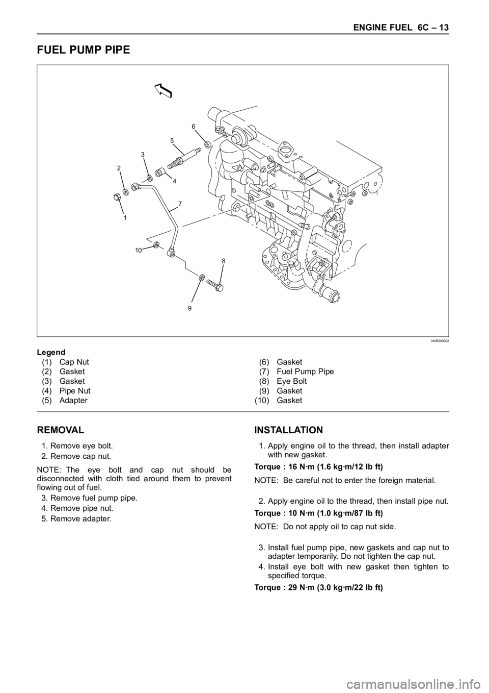
FUEL PUMP PIPE
6
23
10
98 5
4
7
1
Legend
(1) Cap Nut
(2) Gasket
(3) Gasket
(4) Pipe Nut
(5) Adapter(6) Gasket
(7) Fuel Pump Pipe
(8) Eye Bolt
(9) Gasket
(10) Gasket
040R200002
REMOVAL
1. Remove eye bolt.
2. Remove cap nut.
NOTE: The eye bolt and cap nut should be
disconnected with cloth tied around them to prevent
flowing out of fuel.
3. Remove fuel pump pipe.
4. Remove pipe nut.
5. Remove adapter.
INSTALLATION
1. Apply engine oil to the thread, then install adapter
with new gasket.
Torque : 16 Nꞏm (1.6 kgꞏm/12 lb ft)
NOTE: Be careful not to enter the foreign material.
2. Apply engine oil to the thread, then install pipe nut.
Torque : 10 Nꞏm (1.0 kgꞏm/87 lb ft)
NOTE: Do not apply oil to cap nut side.
3. Install fuel pump pipe, new gaskets and cap nut to
adapter temporarily. Do not tighten the cap nut.
4. Install eye bolt with new gasket then tighten to
specified torque.
Torque : 29 Nꞏm (3.0 kgꞏm/22 lb ft)
Page 1859 of 6000

6C – 14 ENGINE FUEL
NOTE:
1) Do not apply oil to the eye bolt.
2) Do not bend the fuel pump pipe.
5. Tifhten cap nut to specified torque.
Torque : 13 Nꞏm (1.3 kgꞏm/113 lb ft)
NOTE: Do not apply oil to the cap nut.
6. Start the engine, check that the fuel leakage is not
found.
Page 1865 of 6000
6C – 20 ENGINE FUEL
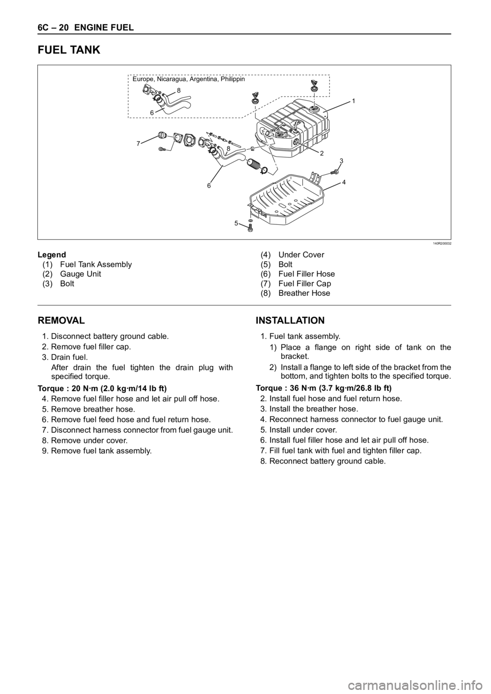
FUEL TANK
REMOVAL
1. Disconnect battery ground cable.
2. Remove fuel filler cap.
3. Drain fuel.
After drain the fuel tighten the drain plug with
specified torque.
Torque : 20 Nꞏm (2.0 kgꞏm/14 lb ft)
4. Remove fuel filler hose and let air pull off hose.
5. Remove breather hose.
6. Remove fuel feed hose and fuel return hose.
7. Disconnect harness connector from fuel gauge unit.
8. Remove under cover.
9. Remove fuel tank assembly.
INSTALLATION
1. Fuel tank assembly.
1) Place a flange on right side of tank on the
bracket.
2) Install a flange to left side of the bracket from the
bottom, and tighten bolts to the specified torque.
Torque : 36 Nꞏm (3.7 kgꞏm/26.8 lb ft)
2. Install fuel hose and fuel return hose.
3. Install the breather hose.
4. Reconnect harness connector to fuel gauge unit.
5. Install under cover.
6. Install fuel filler hose and let air pull off hose.
7. Fill fuel tank with fuel and tighten filler cap.
8. Reconnect battery ground cable.
1
2
4
8
678 Europe, Nicaragua, Argentina, Philippin
6
5
3
Legend
(1) Fuel Tank Assembly
(2) Gauge Unit
(3) Bolt(4) Under Cover
(5) Bolt
(6) Fuel Filler Hose
(7) Fuel Filler Cap
(8) Breather Hose
140R200032
Page 1866 of 6000
ENGINE FUEL 6C – 21
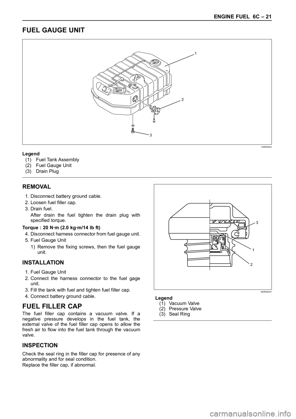
FUEL GAUGE UNIT
1
2
3
140R200033
REMOVAL
1. Disconnect battery ground cable.
2. Loosen fuel filler cap.
3. Drain fuel.
After drain the fuel tighten the drain plug with
specified torque.
Torque : 20 Nꞏm (2.0 kgꞏm/14 lb ft)
4. Disconnect harness connector from fuel gauge unit.
5. Fuel Gauge Unit
1) Remove the fixing screws, then the fuel gauge
unit.
INSTALLATION
1. Fuel Gauge Unit
2. Connect the harness connector to the fuel gage
unit.
3. Fill the tank with fuel and tighten fuel filler cap.
4. Connect battery ground cable.
FUEL FILLER CAP
The fuel filler cap contains a vacuum valve. If a
negative pressure develops in the fuel tank, the
external valve of the fuel filler cap opens to allow the
fresh air to flow into the fuel tank through the vacuum
valve.
INSPECTION
Check the seal ring in the filler cap for presence of any
abnormality and for seal condition.
Replace the filler cap, if abnormal.Legend
(1) Vacuum Valve
(2) Pressure Valve
(3) Seal Ring Legend
(1) Fuel Tank Assembly
(2) Fuel Gauge Unit
(3) Drain Plug
1
3
2
060R200247
Page 1899 of 6000
6E–6
4JX1–TC ENGINE DRIVEABILITY AND EMISSIONS
Removal Procedure 6E–212. . . . . . . . . . . . . . . . . . . .
Installation Procedure 6E–212. . . . . . . . . . . . . . . . . .
Fuel Filter Cap 6E–213. . . . . . . . . . . . . . . . . . . . . . . . . .
General Description 6E–213. . . . . . . . . . . . . . . . . . . .
Inspection Procedure 6E–213. . . . . . . . . . . . . . . . . .
Fuel Filter 6E–213. . . . . . . . . . . . . . . . . . . . . . . . . . . . . .
Removal and Installation Procedure 6E–213. . . . . .
Fuel Gauge Unit 6E–213. . . . . . . . . . . . . . . . . . . . . . . .
Removal Procedure 6E–213. . . . . . . . . . . . . . . . . . . .
Installation Procedure 6E–214. . . . . . . . . . . . . . . . . .
Fuel Injectors 6E–214. . . . . . . . . . . . . . . . . . . . . . . . . . .
Removal and Installation Procedure 6E–214. . . . . .
Fuel Temperature Sensor 6E–214. . . . . . . . . . . . . . . .
Removal Procedure 6E–214. . . . . . . . . . . . . . . . . . . .
Installation Procedure 6E–215. . . . . . . . . . . . . . . . . .
Rail Pressure (RP) Sensor 6E–216. . . . . . . . . . . . . . .
Removal Procedure 6E–216. . . . . . . . . . . . . . . . . . . .
Installation Procedure 6E–216. . . . . . . . . . . . . . . . . .
Fuel Tank 6E–216. . . . . . . . . . . . . . . . . . . . . . . . . . . . . .
Removal Procedure 6E–216. . . . . . . . . . . . . . . . . . . .
Throttle Body (TB) 6E–217. . . . . . . . . . . . . . . . . . . . . . .
Removal Procedure 6E–217. . . . . . . . . . . . . . . . . . . .
Installation Procedure 6E–217. . . . . . . . . . . . . . . . . .
Air Conditioning (A/C) Relay 6E–217. . . . . . . . . . . . . .
Removal Procedure 6E–217. . . . . . . . . . . . . . . . . . . .
Installation Procedure 6E–217. . . . . . . . . . . . . . . . . .
Exhaust Gas Recirculation (EGR) Vacuum
Switch Valve (VSV) 6E–217. . . . . . . . . . . . . . . . . . . . .
Removal Procedure 6E–217. . . . . . . . . . . . . . . . . . . .
Installation Procedure 6E–218. . . . . . . . . . . . . . . . . .
Electronic Vacuum Regurating Valve (EVRV) 6E–219
Removal Procedure 6E–219. . . . . . . . . . . . . . . . . . . .
Installation Procedure 6E–220. . . . . . . . . . . . . . . . . .
Wiring and Connectors 6E–220. . . . . . . . . . . . . . . . . . .
Wiring Harness Service 6E–220. . . . . . . . . . . . . . . .
Connectors and Terminals 6E–220. . . . . . . . . . . . . .
Wire Harness Repair: Twisted Shielded
Cable 6E–220. . . . . . . . . . . . . . . . . . . . . . . . . . . . . . . . .
Removal Procedure 6E–220. . . . . . . . . . . . . . . . . . . .
Installation Procedure 6E–221. . . . . . . . . . . . . . . . . .
Twisted Leads 6E–221. . . . . . . . . . . . . . . . . . . . . . . . . .
Removal Procedure 6E–221. . . . . . . . . . . . . . . . . . . .
Installation Procedure 6E–222. . . . . . . . . . . . . . . . . .
Weather-Pack Connector 6E–223. . . . . . . . . . . . . . . . .
Tools Required 6E–223. . . . . . . . . . . . . . . . . . . . . . . .
Removal Procedure 6E–223. . . . . . . . . . . . . . . . . . . . Installation Procedure 6E–223. . . . . . . . . . . . . . . . . .
Com-Pack III 6E–224. . . . . . . . . . . . . . . . . . . . . . . . . . .
General Information 6E–224. . . . . . . . . . . . . . . . . . . .
Metri-Pack 6E–224. . . . . . . . . . . . . . . . . . . . . . . . . . . . .
Tools Required 6E–224. . . . . . . . . . . . . . . . . . . . . . . .
Removal Procedure 6E–224
. . . . . . . . . . . . . . . . . . . .
Installation Procedure 6E–224. . . . . . . . . . . . . . . . . .
General Description
(ECM and Sensors) 6E–225. . . . . . . . . . . . . . . . . . . . .
57X Reference ECM Input 6E–225. . . . . . . . . . . . . .
A/C Request Signal 6E–225. . . . . . . . . . . . . . . . . . . .
Crankshaft Position (CKP) Sensor 6E–225. . . . . . .
Camshaft Position (CMP) Sensor and
Signal 6E–225. . . . . . . . . . . . . . . . . . . . . . . . . . . . . . .
Engine Coolant Temperature (ECT) Sensor 6E–225
Electrically Erasable Programmable Read
Only Memory (EEPROM) 6E–225. . . . . . . . . . . . . .
Intake Air Temperature (IAT) Sensor 6E–225. . . . .
Manifold Absolute Pressure (MAP) Sensor 6E–226
Engine Control Module (ECM) 6E–226. . . . . . . . . . .
ECM Function 6E–226. . . . . . . . . . . . . . . . . . . . . . . . .
ECM Components 6E–226. . . . . . . . . . . . . . . . . . . . .
ECM Voltage Description 6E–226. . . . . . . . . . . . . . .
ECM Input/Outputs 6E–226. . . . . . . . . . . . . . . . . . . .
ECM Service Precautions 6E–227. . . . . . . . . . . . . .
Intake Throttle Position (ITP) Sensor 6E–227. . . . .
Transmission Range Switch 6E–227. . . . . . . . . . . . .
Accelerator Position Sensor (AP) 6E–227. . . . . . . .
Aftermarket Electrical and Vacuum
Equipment 6E–227. . . . . . . . . . . . . . . . . . . . . . . . . . .
Electrostatic Discharge Damage 6E–227. . . . . . . . .
General Description (Air Induction) 6E–228. . . . . . . .
Air Induction System 6E–228. . . . . . . . . . . . . . . . . . .
General Description (Fuel Metering) 6E–228. . . . . . .
Deceleration Mode 6E–228. . . . . . . . . . . . . . . . . . . .
Fuel Injector 6E–228. . . . . . . . . . . . . . . . . . . . . . . . . .
Fuel Metering System Components 6E–228. . . . . .
A/C Clutch Diagnosis 6E–228. . . . . . . . . . . . . . . . . . . .
A/C Request Signal 6E–228. . . . . . . . . . . . . . . . . . . .
General Description Exhaust Gas
Recirculation (EGR) System 6E–228. . . . . . . . . . . . .
EGR Purpose 6E–228. . . . . . . . . . . . . . . . . . . . . . . . .
Fuse and Relay Panel
(Underhood Electrical Center) RHD 6E–229. . . . . . .
Fuse and Relay Panel
(Underhood Electrical Center) LHD 6E–230. . . . . . .
Page 1919 of 6000
6E–26
4JX1–TC ENGINE DRIVEABILITY AND EMISSIONS
Output Components:
Output components are diagnosed for proper response to
control module commands. Components where
functional monitoring is not feasible will be monitored for
circuit continuity and out-of-range values if applicable.
Output components to be monitored include, but are not
limited to, the following circuit:
EGR VSV
EGR EVRV
Electronic Transmission controls
Injector
Intake throttle
Glow plug
MIL control
Refer to ECM and Sensors in General Descriptions.
Passive and Active Diagnostic Tests
A passive test is a diagnostic test which simply monitors a
vehicle system or component. Conversely, an active test,
actually takes some sort of action when performing
diagnostic functions, often in response to a failed passive
test.
Intrusive Diagnostic Tests
This is any on-board test run by the Diagnostic
Management System which may have an effect on
vehicle performance or emission levels.
Warm-Up Cycle
A warm-up cycle means that engine at temperature must
reach a minimum of 70
C (160F) and rise at least 22C
(40
F) over the course of a trip.
Freeze Frame
Freeze Frame is an element of the Diagnostic
Management System which stores various vehicle
information at the moment an emissions-related fault is
stored in memory and when the MIL is commanded on.
These data can help to identify the cause of a fault. Refer
to
Storing And Erasing Freeze Fame Data for more
detailed information.
Failure Records
Failure Records data is an enhancement of the OBD
Freeze Frame feature. Failure Records store the same
vehicle information as does Freeze Frame, but it will store
that information for any fault which is stored in on-board
memory, while Freeze Frame stores information only for
emission-related faults that command the MIL on.
Common OBD Terms
Diagnostic
When used as a noun, the word diagnostic refers to any
on-board test run by the vehicle’s Diagnostic
Management System. A diagnostic is simply a test run on
a system or component to determine if the system or
component is operating according to specification. There
are many diagnostics, shown in the following list:
EGR
engine speed
vehicle speed
ECT
MAP
VSV
IAT
ITP
AP
FT (Fuel Temp)
RP (Rail Pressure)
OT (Oil Temp)
EGR EVRV
Idle SW
Brake SW
The Diagnostic Executive
The Diagnostic Executive is a unique segment of
software which is designed to coordinate and prioritize
the diagnostic procedures as well as define the protocol
for recording and displaying their results. The main
responsibilities of the Diagnostic Executive are listed as
follows:
Commanding the MIL (“Check Engine” lamp) on and
off
DTC logging and clearing
Freeze Frame data for the first emission related DTC
recorded
Current status information on each diagnostic
Diagnostic Information
The diagnostic charts and functional checks are designed
to locate a faulty circuit or component through a process
of logical decisions. The charts are prepared with the
requirement that the vehicle functioned correctly at the
time of assembly and that there are not multiple faults
present.
There is a continuous self-diagnosis on certain control
functions. This diagnostic capability is complemented by
the diagnostic procedures contained in this manual. The
language of communicating the source of the malfunction
is a system of diagnostic trouble codes. When a
malfunction is detected by the control module, a
diagnostic trouble code is set and the Malfunction
Indicator Lamp (MIL) (“Check Engine” lamp) is
illuminated.
Malfunction Indicator Lamp (MIL)
The Malfunction Indicator Lamp (MIL) looks the same as
the MIL you are already familiar with “Check Engine”
lamp.
Basically, the MIL is turned on when the ECM detects a
DTC that will impact the vehicle emissions.
When the MIL remains “ON” while the engine is
running, or when a malfunction is suspected due to a
driveability or emissions problem, a Powertrain
On-Board Diagnostic (OBD) System Check must be
performed. The procedures for these checks are
given in On-Board Diagnostic (OBD) System Check.
These checks will expose faults which may not be
detected if other diagnostics are performed first.
DTC Types
Characteristic of Code
Page 2080 of 6000
6E–187 4JX1–TC ENGINE DRIVEABILITY AND EMISSIONS
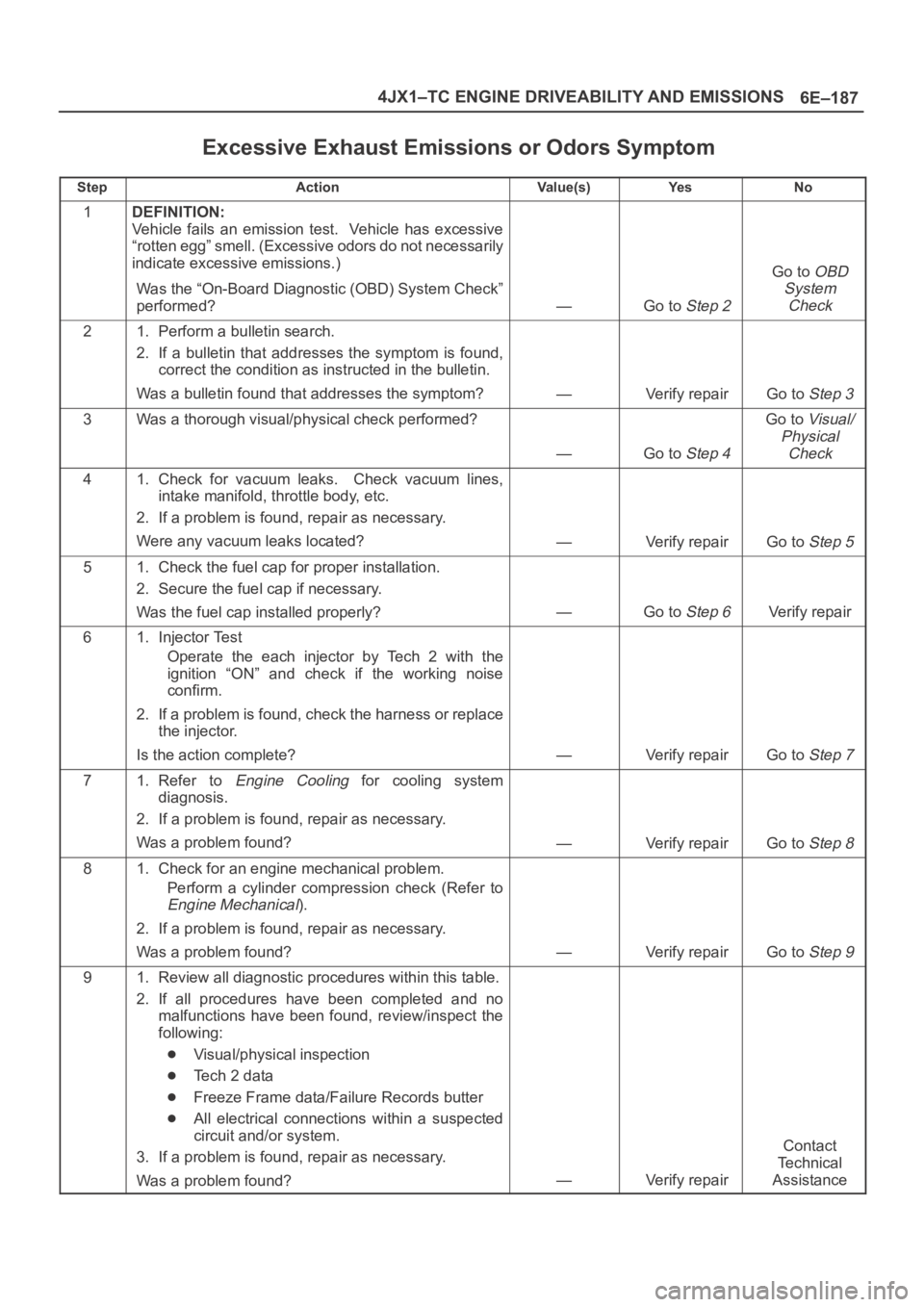
Excessive Exhaust Emissions or Odors Symptom
StepActionVa l u e ( s )Ye sNo
1DEFINITION:
Vehicle fails an emission test. Vehicle has excessive
“rotten egg” smell. (Excessive odors do not necessarily
indicate excessive emissions.)
Was the “On-Board Diagnostic (OBD) System Check”
performed?
—Go to Step 2
Go to OBD
System
Check
21. Perform a bulletin search.
2. If a bulletin that addresses the symptom is found,
correct the condition as instructed in the bulletin.
Was a bulletin found that addresses the symptom?
—Verify repairGo to Step 3
3Was a thorough visual/physical check performed?
—Go to Step 4
Go to Visual/
Physical
Check
41. Check for vacuum leaks. Check vacuum lines,
intake manifold, throttle body, etc.
2. If a problem is found, repair as necessary.
Were any vacuum leaks located?
—Verify repairGo to Step 5
51. Check the fuel cap for proper installation.
2. Secure the fuel cap if necessary.
Was the fuel cap installed properly?
—Go to Step 6Verify repair
61. Injector Test
Operate the each injector by Tech 2 with the
ignition “ON” and check if the working noise
confirm.
2. If a problem is found, check the harness or replace
the injector.
Is the action complete?
—Verify repairGo to Step 7
71. Refer to Engine Cooling for cooling system
diagnosis.
2. If a problem is found, repair as necessary.
Was a problem found?
—Verify repairGo to Step 8
81. Check for an engine mechanical problem.
Perform a cylinder compression check (Refer to
Engine Mechanical).
2. If a problem is found, repair as necessary.
Was a problem found?
—Verify repairGo to Step 9
91. Review all diagnostic procedures within this table.
2. If all procedures have been completed and no
malfunctions have been found, review/inspect the
following:
Visual/physical inspection
Te c h 2 d a t a
Freeze Frame data/Failure Records butter
All electrical connections within a suspected
circuit and/or system.
3. If a problem is found, repair as necessary.
Was a problem found?
—Verify repair
Contact
Te c h n i c a l
Assistance
Page 2106 of 6000
6E–213 4JX1–TC ENGINE DRIVEABILITY AND EMISSIONS
3. Connect the electrical connector to the AP sensor.
035RW060
4. Connect the negative battery cable.
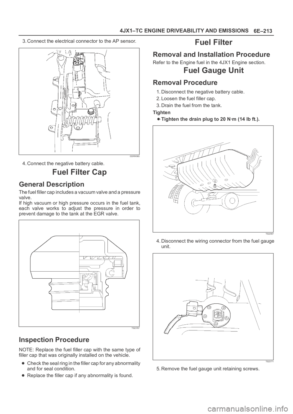
Fuel Filter Cap
General Description
The fuel filler cap includes a vacuum valve and a pressure
valve.
If high vacuum or high pressure occurs in the fuel tank,
each valve works to adjust the pressure in order to
prevent damage to the tank at the EGR valve.
TS23767
Inspection Procedure
NOTE: Replace the fuel filler cap with the same type of
filler cap that was originally installed on the vehicle.
Check the seal ring in the filler cap for any abnormality
and for seal condition.
Replace the filler cap if any abnormality is found.
Fuel Filter
Removal and Installation Procedure
Refer to the Engine fuel in the 4JX1 Engine section.
Fuel Gauge Unit
Removal Procedure
1. Disconnect the negative battery cable.
2. Loosen the fuel filler cap.
3. Drain the fuel from the tank.
Tighten
Tighten the drain plug to 20 Nꞏm (14 lb ft.).
TS22907
4. Disconnect the wiring connector from the fuel gauge
unit.
TS23771
5. Remove the fuel gauge unit retaining screws.