Page 4902 of 6000
6E–245 ENGINE DRIVEABILITY AND EMISSIONS
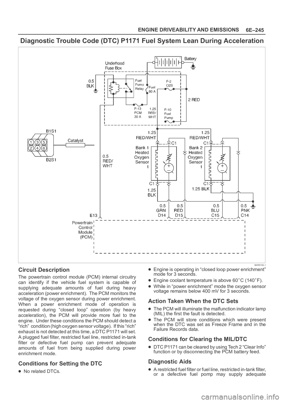
Diagnostic Trouble Code (DTC) P1171 Fuel System Lean During Acceleration
060RW193–1
Circuit Description
The powertrain control module (PCM) internal circuitry
can identify if the vehicle fuel system is capable of
supplying adequate amounts of fuel during heavy
acceleration (power enrichment). The PCM monitors the
voltage of the oxygen sensor during power enrichment.
When a power enrichment mode of operation is
requested during “closed loop” operation (by heavy
acceleration), the PCM will provide more fuel to the
engine. Under these conditions the PCM should detect a
“rich” condition (high oxygen sensor voltage). If this “rich”
exhaust is not detected at this time, a DTC P1171 will set.
A plugged fuel filter, restricted fuel line, restricted in-tank
filter or defective fuel pump can prevent adequate
amounts of fuel from being supplied during power
enrichment mode.
Conditions for Setting the DTC
No related DTCs.
Engine is operating in “closed loop power enrichment”
mode for 3 seconds.
Engine coolant temperature is above 60C (140F).
While in “power enrichment” mode the oxygen sensor
voltage remains below 400 mV for 3 seconds.
Action Taken When the DTC Sets
The PCM will illuminate the malfunction indicator lamp
(MIL) the first the fault is detected.
The PCM will store conditions which were present
when the DTC was set as Freeze Frame and in the
Failure Records data.
Conditions for Clearing the MIL/DTC
DTC P1171 can be cleared by using Tech 2 “Clear Info”
function or by disconnecting the PCM battery feed.
Diagnostic Aids
A restricted fuel filter or fuel line, restricted in-tank filter,
or a defective fuel pomp may supply adequate
Page 4934 of 6000
6E–277 ENGINE DRIVEABILITY AND EMISSIONS
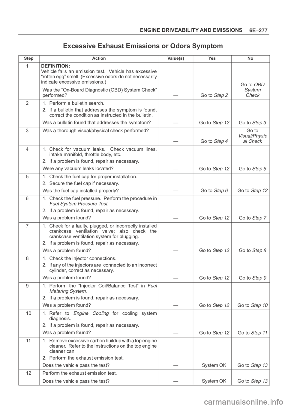
Excessive Exhaust Emissions or Odors Symptom
StepActionVa l u e ( s )Ye sNo
1DEFINITION:
Vehicle fails an emission test. Vehicle has excessive
“rotten egg” smell. (Excessive odors do not necessarily
indicate excessive emissions.)
Was the “On-Board Diagnostic (OBD) System Check”
performed?
—Go to Step 2
Go to OBD
System
Check
21. Perform a bulletin search.
2. If a bulletin that addresses the symptom is found,
correct the condition as instructed in the bulletin.
Was a bulletin found that addresses the symptom?
—Go to Step 12Go to Step 3
3Was a thorough visual/physical check performed?
—Go to Step 4
Go to
Visual/Physic
al Check
41. Check for vacuum leaks. Check vacuum lines,
intake manifold, throttle body, etc.
2. If a problem is found, repair as necessary.
Were any vacuum leaks located?
—Go to Step 12Go to Step 5
51. Check the fuel cap for proper installation.
2. Secure the fuel cap if necessary.
Was the fuel cap installed properly?
—Go to Step 6Go to Step 12
61. Check the fuel pressure. Perform the procedure in
Fuel System Pressure Test.
2. If a problem is found, repair as necessary.
Was a problem found?
—Go to Step 12Go to Step 7
71. Check for a faulty, plugged, or incorrectly installed
crankcase ventilation valve; also check the
crankcase ventilation system for plugging.
2. If a problem is found, repair as necessary.
Was a problem found?
—Go to Step 12Go to Step 8
81. Check the injector connections.
2. If any of the injectors are connected to an incorrect
cylinder, correct as necessary.
Was a problem found?
—Go to Step 12Go to Step 9
91. Perform the “Injector Coil/Balance Test” in Fuel
Metering System
.
2. If a problem is found, repair as necessary.
Was a problem found?
—Go to Step 12Go to Step 10
101. Refer to Engine Cooling for cooling system
diagnosis.
2. If a problem is found, repair as necessary.
Was a problem found?
—Go to Step 12Go to Step 11
111. Remove excessive carbon buildup with a top engine
cleaner. Refer to the instructions on the top engine
cleaner can.
2. Perform the exhaust emission test.
Does the vehicle pass the test?
—System OKGo to Step 13
12Perform the exhaust emission test.
Does the vehicle pass the test?
—System OKGo to Step 13
Page 4967 of 6000
6E–310
ENGINE DRIVEABILITY AND EMISSIONS
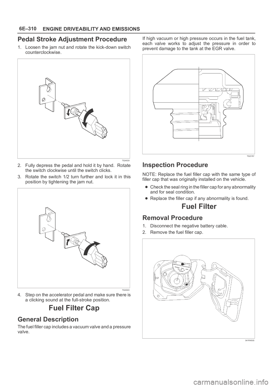
Pedal Stroke Adjustment Procedure
1. Loosen the jam nut and rotate the kick-down switch
counterclockwise.
TS24039
2. Fully depress the pedal and hold it by hand. Rotate
the switch clockwise until the switch clicks.
3. Rotate the switch 1/2 turn further and lock it in this
position by tightening the jam nut.
TS24040
4. Step on the accelerator pedal and make sure there is
a clicking sound at the full-stroke position.
Fuel Filter Cap
General Description
The fuel filler cap includes a vacuum valve and a pressure
valve.If high vacuum or high pressure occurs in the fuel tank,
each valve works to adjust the pressure in order to
prevent damage to the tank at the EGR valve.
TS23767
Inspection Procedure
NOTE: Replace the fuel filler cap with the same type of
filler cap that was originally installed on the vehicle.
Check the seal ring in the filler cap for any abnormality
and for seal condition.
Replace the filler cap if any abnormality is found.
Fuel Filter
Removal Procedure
1. Disconnect the negative battery cable.
2. Remove the fuel filler cap.
041RW005
Page 4969 of 6000
6E–312
ENGINE DRIVEABILITY AND EMISSIONS
Installation Procedure
1. Install the fuel filter in the correct direction.
041RW008
2. Install the bolt on the fuel filter holder.
041RW007
3. Connect the fuel line on the engine side.
4. Connect the fuel line on the fuel tank side.
041RW006
5. Install the fuel filler cap.
041RW005
6. Connect the negative battery cable.
Page 4970 of 6000
6E–313 ENGINE DRIVEABILITY AND EMISSIONS
Fuel Gauge Unit
Removal Procedure
1. Disconnect the negative battery cable.
2. Loosen the fuel filler cap.
3. Drain the fuel from the tank.
Tighten
Tighten the drain plug to 20 Nꞏm (14 lb ft.).
TS22907
4. Disconnect the wiring connector from the fuel gauge
unit.
TS23771
5. Remove the fuel gauge unit retaining screws.
6. Remove the fuel gauge unit.
Cover or plug the fuel tank to prevent dust, dirt, or
debris from entering the tank.
TS22911
Installation Procedure
1. Install the fuel gauge unit.
2. Install the fuel gauge unit retaining screws.
TS22911
Page 4971 of 6000
6E–314
ENGINE DRIVEABILITY AND EMISSIONS
3. Connect the wiring connector to the fuel gauge unit.
TS23771
4. Fill the fuel tank with fuel.
Tighten the fuel filler cap.
Check for leaks at the fuel gauge unit gasket.
5. Connect the negative battery cable.
Fuel Injectors
Removal Procedure
NOTE: If the fuel injectors are leaking, the engine oil may
be contaminated with fuel. Check the oil for signs of
contamination and change the oil and the filter if
necessary.
NOTE: Use care in removing the fuel injectors in order to
prevent damage to the fuel injector electrical connector
pins or the fuel injector nozzles. The fuel injector is an
electrical component and should not be immersed in any
type of cleaner as this may damage the fuel injector.
IMPORTANT:Fuel injectors are serviced as a complete
assembly only.
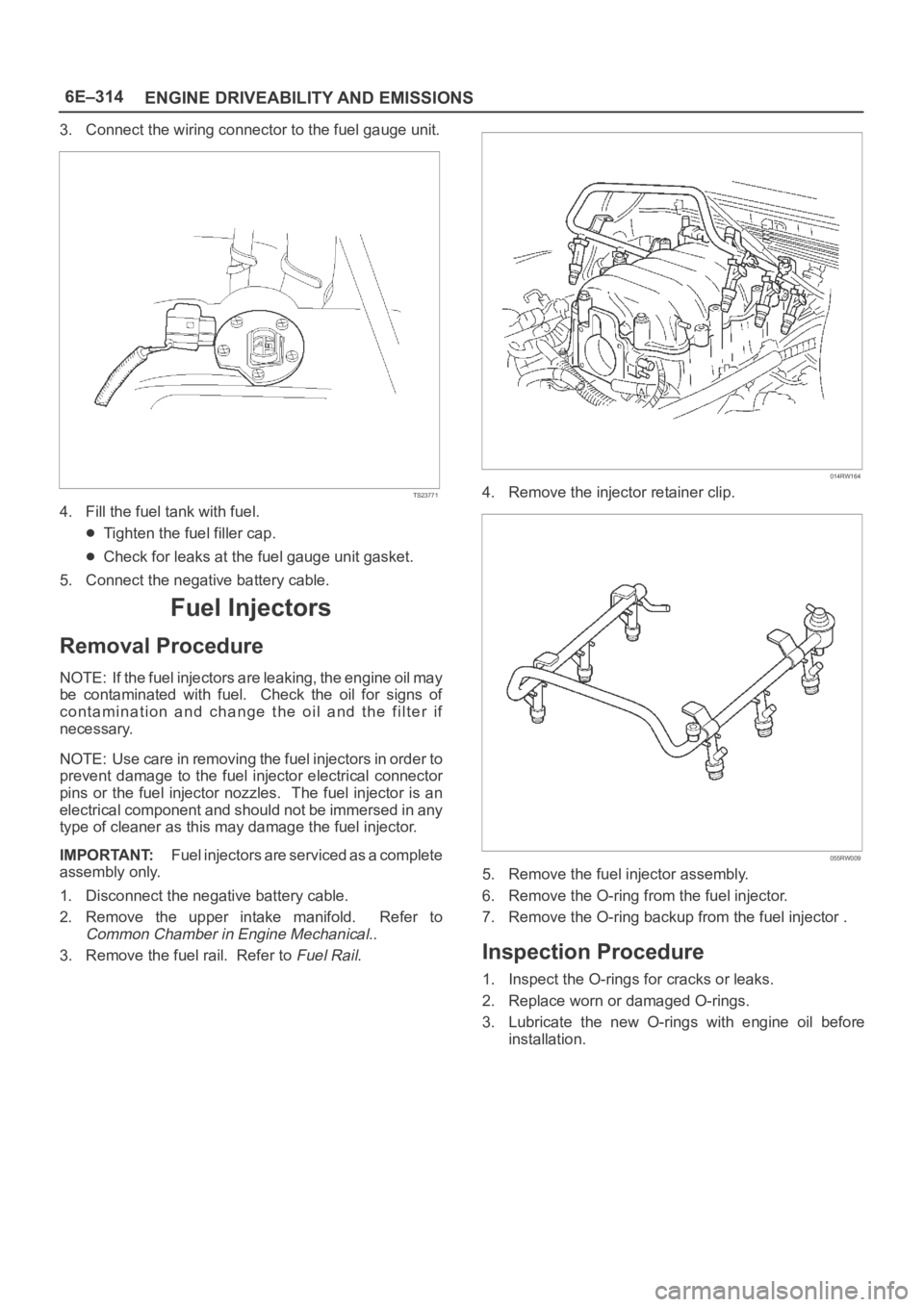
1. Disconnect the negative battery cable.
2. Remove the upper intake manifold. Refer to
Common Chamber in Engine Mechanical..
3. Remove the fuel rail. Refer to
Fuel Rail.
014RW164
4. Remove the injector retainer clip.
055RW009
5. Remove the fuel injector assembly.
6. Remove the O-ring from the fuel injector.
7. Remove the O-ring backup from the fuel injector .
Inspection Procedure
1. Inspect the O-rings for cracks or leaks.
2. Replace worn or damaged O-rings.
3. Lubricate the new O-rings with engine oil before
installation.
Page 4974 of 6000
6E–317 ENGINE DRIVEABILITY AND EMISSIONS
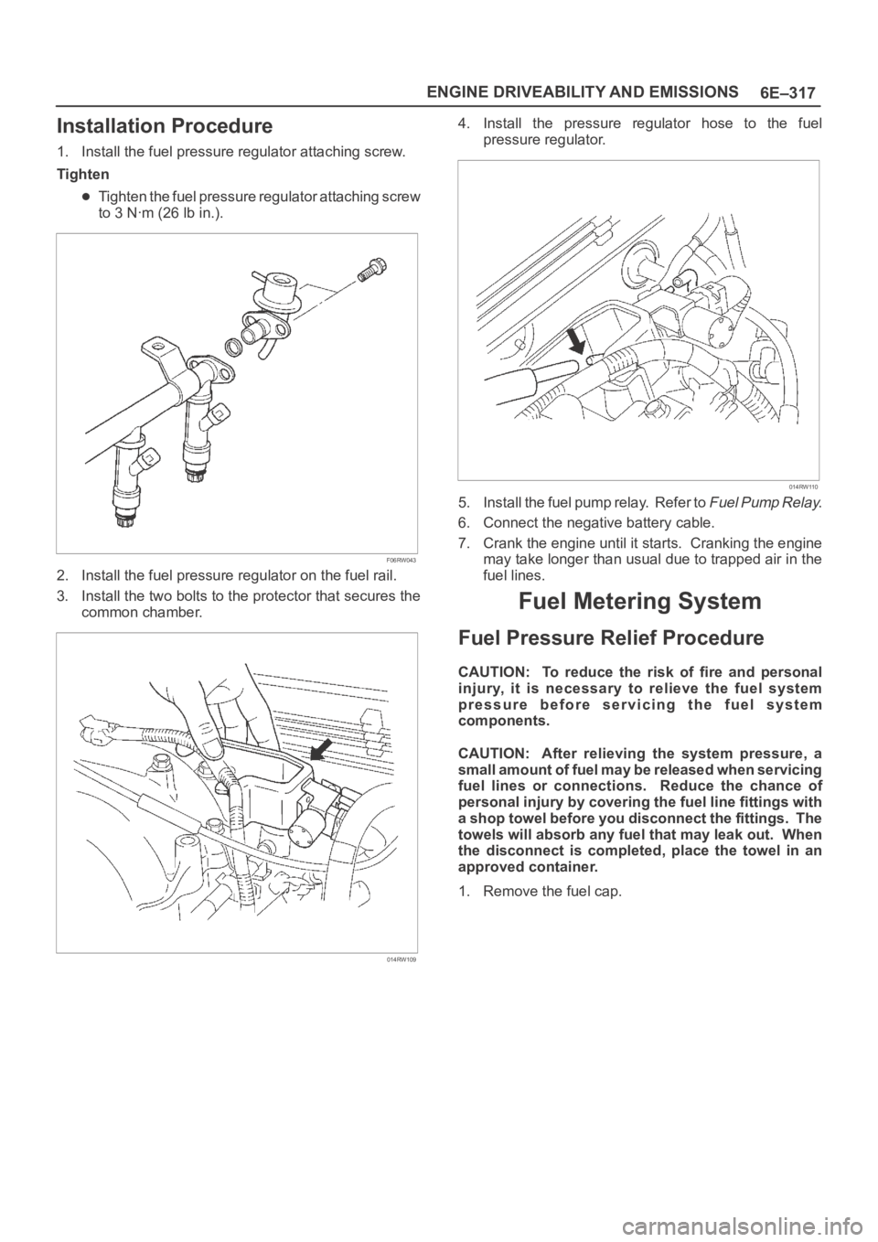
Installation Procedure
1. Install the fuel pressure regulator attaching screw.
Tighten
Tighten the fuel pressure regulator attaching screw
to 3 Nꞏm (26 lb in.).
F06RW043
2. Install the fuel pressure regulator on the fuel rail.
3. Install the two bolts to the protector that secures the
common chamber.
014RW109
4. Install the pressure regulator hose to the fuel
pressure regulator.
014RW110
5. Install the fuel pump relay. Refer to Fuel Pump Relay.
6. Connect the negative battery cable.
7. Crank the engine until it starts. Cranking the engine
may take longer than usual due to trapped air in the
fuel lines.
Fuel Metering System
Fuel Pressure Relief Procedure
CAUTION: To reduce the risk of fire and personal
injury, it is necessary to relieve the fuel system
pressure before servicing the fuel system
components.
CAUTION: After relieving the system pressure, a
small amount of fuel may be released when servicing
fuel lines or connections. Reduce the chance of
personal injury by covering the fuel line fittings with
a shop towel before you disconnect the fittings. The
towels will absorb any fuel that may leak out. When
the disconnect is completed, place the towel in an
approved container.
1. Remove the fuel cap.
Page 4975 of 6000
6E–318
ENGINE DRIVEABILITY AND EMISSIONS
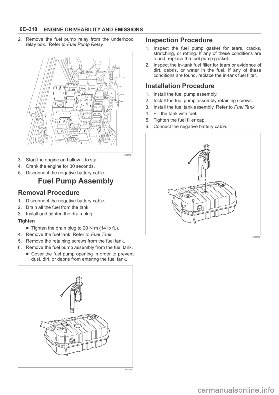
2. Remove the fuel pump relay from the underhood
relay box. Refer to
Fuel Pump Relay.
TS23976R
3. Start the engine and allow it to stall.
4. Crank the engine for 30 seconds.
5. Disconnect the negative battery cable.
Fuel Pump Assembly
Removal Procedure
1. Disconnect the negative battery cable.
2. Drain all the fuel from the tank.
3. Install and tighten the drain plug.
Tighten
Tighten the drain plug to 20 Nꞏm (14 lb ft.).
4. Remove the fuel tank. Refer to
Fuel Tank.
5. Remove the retaining screws from the fuel tank.
6. Remove the fuel pump assembly from the fuel tank.
Cover the fuel pump opening in order to prevent
dust, dirt, or debris from entering the fuel tank.
TS23795
Inspection Procedure
1. Inspect the fuel pump gasket for tears, cracks,
stretching, or rotting. If any of these conditions are
found, replace the fuel pump gasket.
2. Inspect the in-tank fuel filter for tears or evidence of
dirt, debris, or water in the fuel. If any of these
conditions are found, replace the in-tank fuel filter.
Installation Procedure
1. Install the fuel pump assembly.
2. Install the fuel pump assembly retaining screws.
3. Install the fuel tank assembly. Refer to
Fuel Tank.
4. Fill the tank with fuel.
5. Tighten the fuel filler cap.
6. Connect the negative battery cable.
TS23795