1998 OPEL FRONTERA fuel cap
[x] Cancel search: fuel capPage 4976 of 6000
6E–319 ENGINE DRIVEABILITY AND EMISSIONS
Fuel Pump Relay
Removal Procedure
1. Remove the fuse and relay box cover from under the
hood.
2. Consult the diagram on the cover to determine which
is the correct relay.
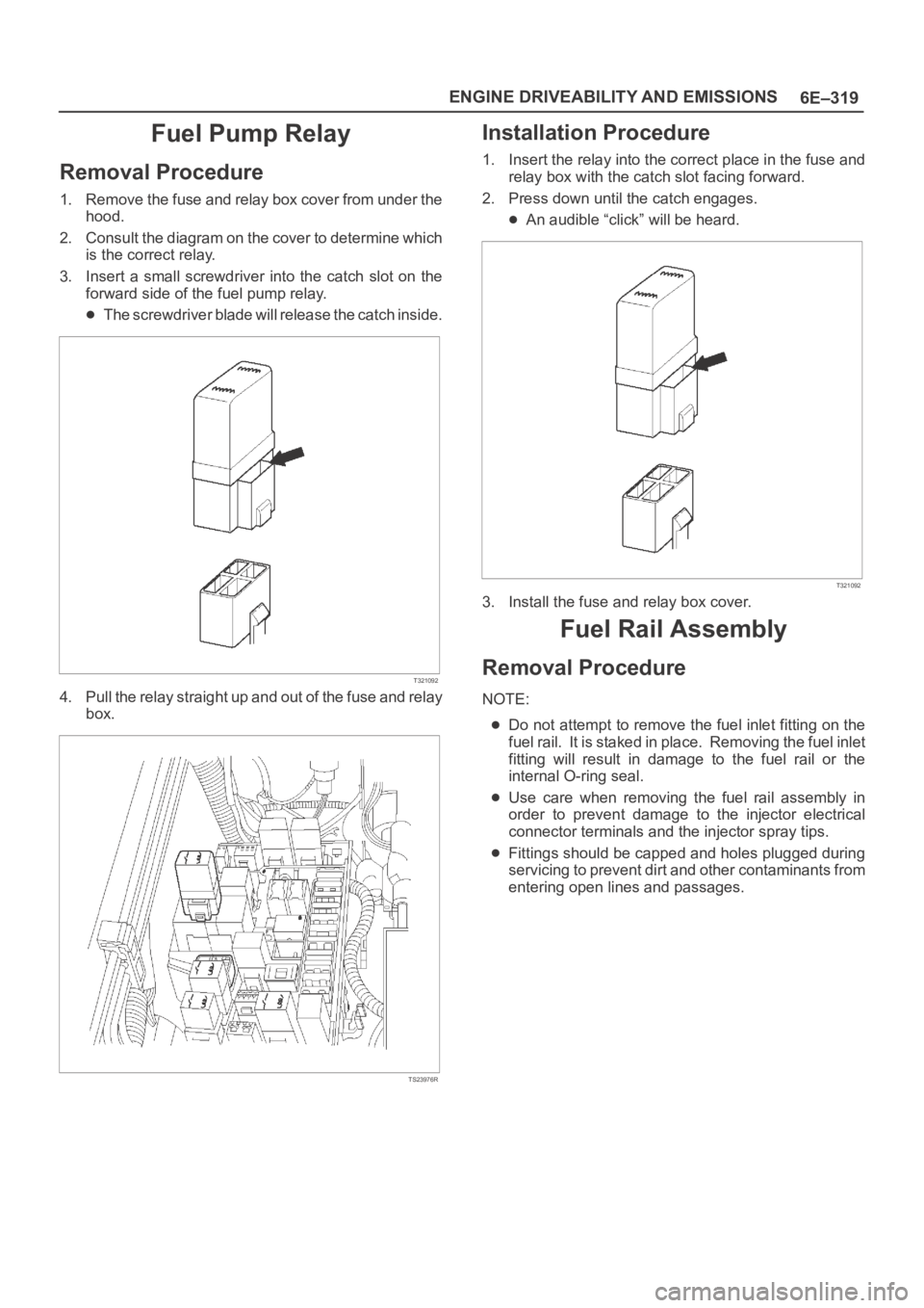
3. Insert a small screwdriver into the catch slot on the
forward side of the fuel pump relay.
The screwdriver blade will release the catch inside.
T321092
4. Pull the relay straight up and out of the fuse and relay
box.
TS23976R
Installation Procedure
1. Insert the relay into the correct place in the fuse and
relay box with the catch slot facing forward.
2. Press down until the catch engages.
An audible “click” will be heard.
T321092
3. Install the fuse and relay box cover.
Fuel Rail Assembly
Removal Procedure
NOTE:
Do not attempt to remove the fuel inlet fitting on the
fuel rail. It is staked in place. Removing the fuel inlet
fitting will result in damage to the fuel rail or the
internal O-ring seal.
Use care when removing the fuel rail assembly in
order to prevent damage to the injector electrical
connector terminals and the injector spray tips.
Fittings should be capped and holes plugged during
servicing to prevent dirt and other contaminants from
entering open lines and passages.
Page 4978 of 6000
6E–321 ENGINE DRIVEABILITY AND EMISSIONS
4. Connect the vacuum hose on Canister VSV and
positive crankcase ventilation hose.
5. Connect the connectors to manifold absolute
pressure sensor, solenoid valve, electric vacuum
sensing valve.
6. Connect the accelerator pedal cable to throttle body
and cable bracket.
7. Install the engine cover.
8. Connect the negative battery cable.
9. Crank the engine until it starts. Cranking the engine
may take longer than usual due to trapped air in the
fuel rail and in the injectors.
Fuel Tank
Removal Procedure
1. Disconnect the negative battery cable.
2. Loosen the fuel filler cap.
3. Drain the fuel from the tank into an approved
container.
4. Install and tighten the drain plug.
Tighten
Tighten the drain plug to 20 Nꞏm (14 lb ft.).
5. Disconnect the fuel filler hose at the fuel tank.
6. Disconnect the air breather hose at the fuel tank.
TS23796
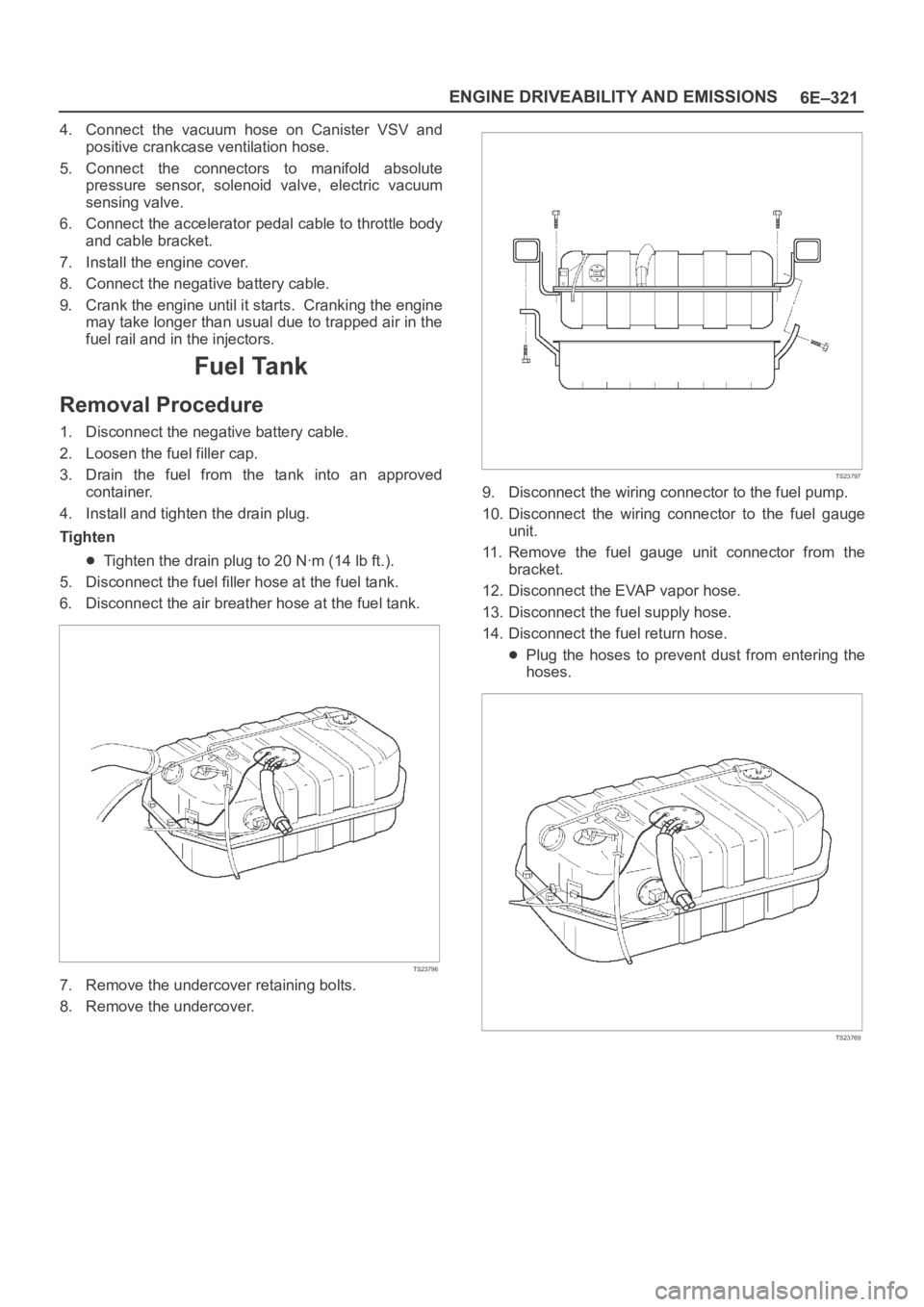
7. Remove the undercover retaining bolts.
8. Remove the undercover.
TS23797
9. Disconnect the wiring connector to the fuel pump.
10. Disconnect the wiring connector to the fuel gauge
unit.
11. Remove the fuel gauge unit connector from the
bracket.
12. Disconnect the EVAP vapor hose.
13. Disconnect the fuel supply hose.
14. Disconnect the fuel return hose.
Plug the hoses to prevent dust from entering the
hoses.
TS23769
Page 4980 of 6000
6E–323 ENGINE DRIVEABILITY AND EMISSIONS
11. Connect the fuel filler fuse at the tank.
12. Connect the air breather hose at the tank.
TS23796
13. Fill the fuel tank with fuel.
14. Tighten the fuel filler cap.
15. Connect the negative battery cable.
Throttle Body (TB)
Removal Procedure
1. Disconnect the negative battery cable.
2. Drain the cooling system. Refer to
Cooling System.
3. Remove the accelerator cable assembly. Refer to
Accelerator Cable in Engine Speed Control System..
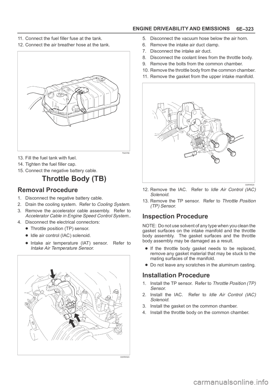
4. Disconnect the electrical connectors:
Throttle position (TP) sensor.
Idle air control (IAC) solenoid.
Intake air temperature (IAT) sensor. Refer to
Intake Air Temperature Sensor.
035RW023
5. Disconnect the vacuum hose below the air horn.
6. Remove the intake air duct clamp.
7. Disconnect the intake air duct.
8. Disconnect the coolant lines from the throttle body.
9. Remove the bolts from the common chamber.
10. Remove the throttle body from the common chamber.
11. Remove the gasket from the upper intake manifold.
035RW024
12. Remove the IAC. Refer to Idle Air Control (IAC)
Solenoid
.
13. Remove the TP sensor. Refer to
Throttle Position
(TP) Sensor
.
Inspection Procedure
NOTE: Do not use solvent of any type when you clean the
gasket surfaces on the intake manifold and the throttle
body assembly. The gasket surfaces and the throttle
body assembly may be damaged as a result.
If the throttle body gasket needs to be replaced,
remove any gasket material that may be stuck to the
mating surfaces of the manifold.
Do not leave any scratches in the aluminum casting.
Installation Procedure
1. Install the TP sensor. Refer to Throttle Position (TP)
Sensor
.
2. Install the IAC. Refer to
Idle Air Control (IAC)
Solenoid
.
3. Install the gasket on the common chamber.
4. Install the throttle body on the common chamber.
Page 5002 of 6000
6E–345 ENGINE DRIVEABILITY AND EMISSIONS
0014
Crankshaft Position (CKP) Sensor
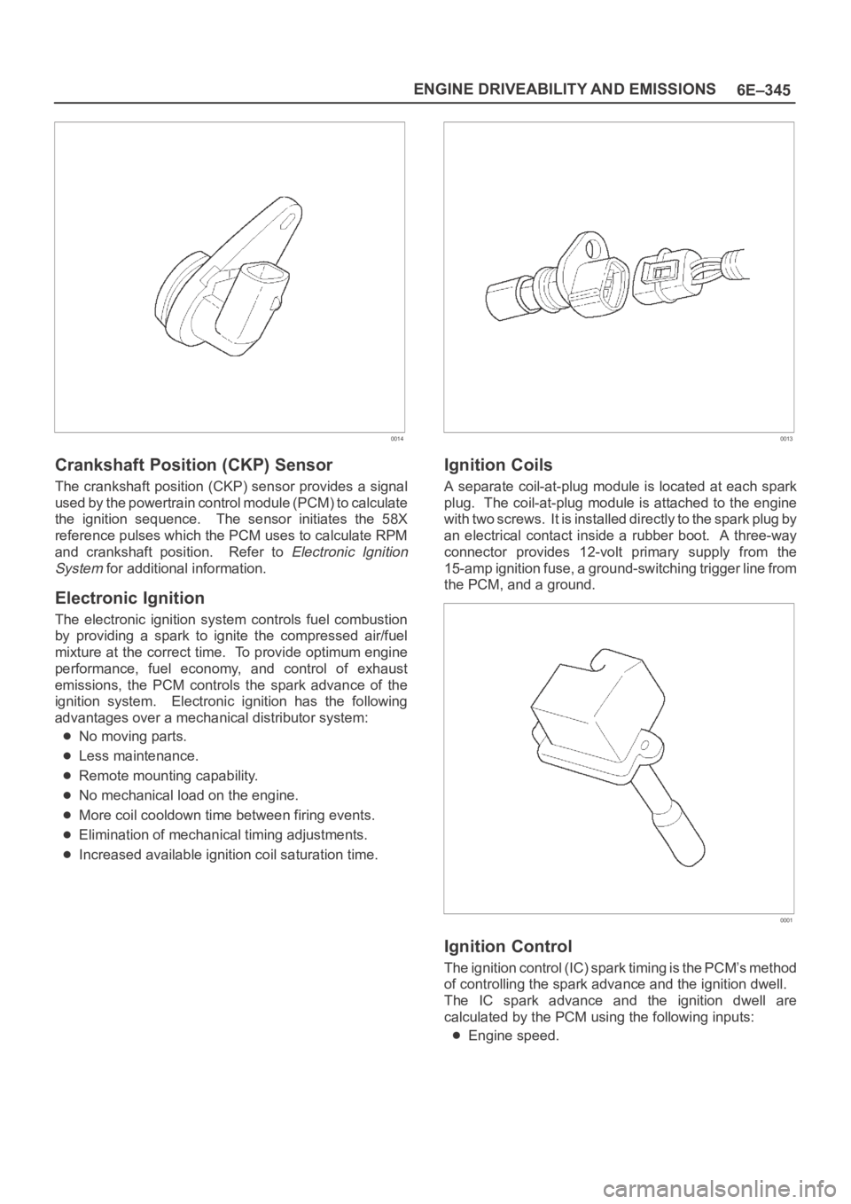
The crankshaft position (CKP) sensor provides a signal
used by the powertrain control module (PCM) to calculate
the ignition sequence. The sensor initiates the 58X
reference pulses which the PCM uses to calculate RPM
and crankshaft position. Refer to
Electronic Ignition
System
for additional information.
Electronic Ignition
The electronic ignition system controls fuel combustion
by providing a spark to ignite the compressed air/fuel
mixture at the correct time. To provide optimum engine
performance, fuel economy, and control of exhaust
emissions, the PCM controls the spark advance of the
ignition system. Electronic ignition has the following
advantages over a mechanical distributor system:
No moving parts.
Less maintenance.
Remote mounting capability.
No mechanical load on the engine.
More coil cooldown time between firing events.
Elimination of mechanical timing adjustments.
Increased available ignition coil saturation time.
0013
Ignition Coils
A separate coil-at-plug module is located at each spark
plug. The coil-at-plug module is attached to the engine
with two screws. It is installed directly to the spark plug by
an electrical contact inside a rubber boot. A three-way
connector provides 12-volt primary supply from the
15-amp ignition fuse, a ground-switching trigger line from
the PCM, and a ground.
0001
Ignition Control
The ignition control (IC) spark timing is the PCM’s method
of controlling the spark advance and the ignition dwell.
The IC spark advance and the ignition dwell are
calculated by the PCM using the following inputs:
Engine speed.
Page 5007 of 6000
6E–350
ENGINE DRIVEABILITY AND EMISSIONS
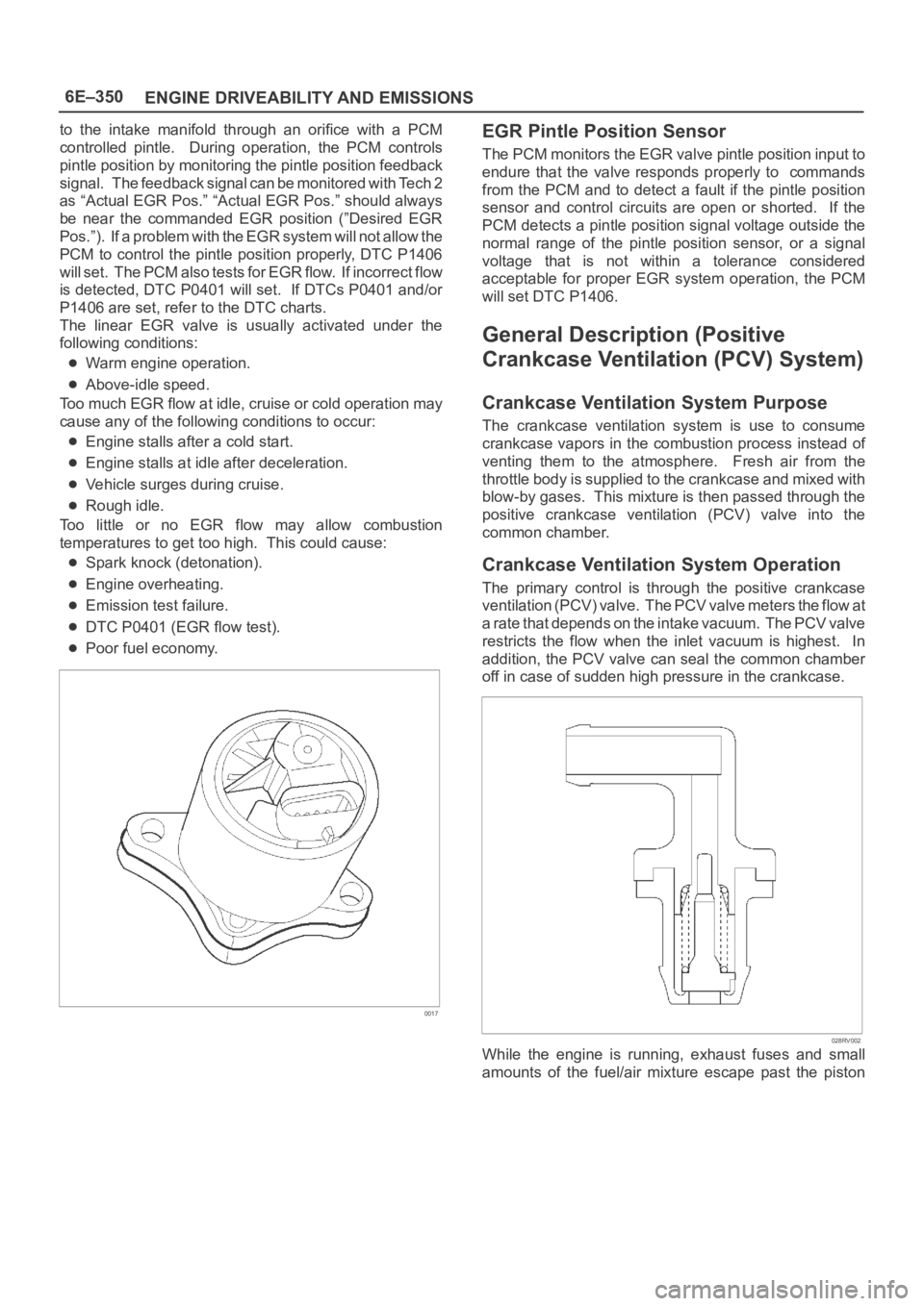
to the intake manifold through an orifice with a PCM
controlled pintle. During operation, the PCM controls
pintle position by monitoring the pintle position feedback
signal. The feedback signal can be monitored with Tech 2
as “Actual EGR Pos.” “Actual EGR Pos.” should always
be near the commanded EGR position (”Desired EGR
Pos.”). If a problem with the EGR system will not allow the
PCM to control the pintle position properly, DTC P1406
will set. The PCM also tests for EGR flow. If incorrect flow
is detected, DTC P0401 will set. If DTCs P0401 and/or
P1406 are set, refer to the DTC charts.
The linear EGR valve is usually activated under the
following conditions:
Warm engine operation.
Above-idle speed.
Too much EGR flow at idle, cruise or cold operation may
cause any of the following conditions to occur:
Engine stalls after a cold start.
Engine stalls at idle after deceleration.
Vehicle surges during cruise.
Rough idle.
Too little or no EGR flow may allow combustion
temperatures to get too high. This could cause:
Spark knock (detonation).
Engine overheating.
Emission test failure.
DTC P0401 (EGR flow test).
Poor fuel economy.
0017
EGR Pintle Position Sensor
The PCM monitors the EGR valve pintle position input to
endure that the valve responds properly to commands
from the PCM and to detect a fault if the pintle position
sensor and control circuits are open or shorted. If the
PCM detects a pintle position signal voltage outside the
normal range of the pintle position sensor, or a signal
voltage that is not within a tolerance considered
acceptable for proper EGR system operation, the PCM
will set DTC P1406.
General Description (Positive
Crankcase Ventilation (PCV) System)
Crankcase Ventilation System Purpose
The crankcase ventilation system is use to consume
crankcase vapors in the combustion process instead of
venting them to the atmosphere. Fresh air from the
throttle body is supplied to the crankcase and mixed with
blow-by gases. This mixture is then passed through the
positive crankcase ventilation (PCV) valve into the
common chamber.
Crankcase Ventilation System Operation
The primary control is through the positive crankcase
v e n t i l a t i o n ( P C V ) v a l v e . T h e PCV valve meters the flow at
a rate that depends on the intake vacuum. The PCV valve
restricts the flow when the inlet vacuum is highest. In
addition, the PCV valve can seal the common chamber
off in case of sudden high pressure in the crankcase.
028RV002
While the engine is running, exhaust fuses and small
amounts of the fuel/air mixture escape past the piston
Page 5275 of 6000
6A – 2 ENGINE MECHANICAL
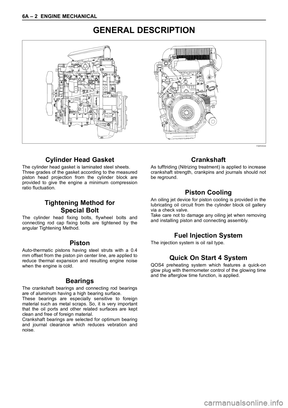
GENERAL DESCRIPTION
Cylinder Head Gasket
The cylinder head gasket is laminated steel sheets.
Three grades of the gasket according to the measured
piston head projection from the cylinder block are
provided to give the engine a minimum compression
ratio fluctuation.
Tightening Method for
Special Bolt
The cylinder head fixing bolts, flywheel bolts and
connecting rod cap fixing bolts are tightened by the
angular Tightening Method.
Piston
Auto-thermatic pistons having steel struts with a 0.4
mm offset from the piston pin center line, are applied to
reduce thermal expansion and resulting engine noise
when the engine is cold.
Bearings
The crankshaft bearings and connecting rod bearings
are of aluminum having a high bearing surface.
These bearings are especially sensitive to foreign
material such as metal scraps. So, it is very important
that the oil ports and other related surfaces are kept
clean and free of foreign material.
Crankshaft bearings are selected for optimum bearing
and journal clearance which reduces vebration and
noise.
Crankshaft
As tufftriding (Nitrizing treatment) is applied to increase
crankshaft strength, crankpins and journals should not
be reground.
Piston Cooling
An oiling jet device for piston cooling is provided in the
lubricating oil circuit from the cylinder block oil gallery
via a check valve.
Take care not to damage any oiling jet when removing
and installing piston and connecting assembly.
Fuel Injection System
The injection system is oil rail type.
Quick On Start 4 System
QOS4 preheating system which features a quick-on
glow plug with thermometer control of the glowing time
and the afterglow time function, is applied.
F06RW048
Page 5306 of 6000

ENGINE MECHANICAL 6A – 33
INTAKE MANIFOLD
REMOVAL
1. Drain engine coolant and disconnect water hose
from thermostat hosing.
2. Remove intercooler assembly
Refer to “Intercooler” in this manual.
3. Remove bracket bolt of oil level gauge guide tube.
4. Remove PCV Hose.
5. Remove hoses from EGR, EGR vacuum sensor
and inlet/outlet of heater.
6. Disconnect harness connector form MAP sensor,
EGR vacuum sensor, ETC sensor, water
temperature unit, IAT sensor and EVRV.
7. Remove high pressure oil pipe.
8. Remove the two way valve.
9. Remove fuel pipe from between intake manifold
and high pressure oil pump.
10. Remove fixing bolts and nuts on the intake
manifold, then remove the intake manifold
assembly.
INSTALLATION
1. Install the intake manifold, tighten bolts and nuts to
the specified torque.
Torque : 20 Nꞏm (2.0 kgꞏm/14.5 lb ft) for bolt and nut
2. Install the fuel pipe and tighten to the specified
torque.To r q u e :
M16 bolt (apply engine oil) 4 Nꞏm (0.4 kgꞏm/2.9
lb ft)
Cap nut (M10) 13Nꞏm (1.3 kgꞏm/9.4 lb ft)
Fuel pipe (M10 apply engine oil) 14 Nꞏm (1.4
kgꞏm/10 lb ft)
3. Install two way valve.
Torque : 20 Nꞏm (2.0 kgꞏm/14.5 lb ft)
4. Fill with about 300 cc of engine oil from the high
pressure oil pipe installation port of the oil rail using
an oil filler. If assembled without filling the oil rail
with oil, the time for starting the engine will be
longer.
5. Install the high pressure oil pipe immediately and
tighten the sleeve nut to the specified torque.
Torque : 80 Nꞏm (8 kgꞏm/57.9 lb ft)
6. Reconnect harness connector to MAP sensor, EGR
vacuum sensor, ETC sensor, Water temperature
unit, IAT sensor and EVRV.
7. Connect the hoses to EGR valve, EGR vacuum
sensor, and water inlet/outlet pipe for heater.
8. Connect PCV hose.
9. Install the oil level gauge guide tube and tighten
bracket bolt.
10. Install the intercooler assembly.
Refer to “Intercooler” in this manual.
11. Connect the hose to the thermostat housing and fill
with engine coolant.
2
3
4
1
025RX001
Legend
(1) Intake Manifold
(2) Throttle Valve Assembly
(3) EGR Valve
(4) Gasket
Page 5382 of 6000
ENGINE FUEL 6C – 1
ENGINE FUEL
CONTENTS
GENERAL DESCRIPTION
General Description . . . . . . . . . . . . . . . . . . 6C–1
On-Vehicle Service . . . . . . . . . . . . . . . . . . 6C–8
Fuel Filter Assembly . . . . . . . . . . . . . . . . 6C–8
Fuel Filter Cartridge . . . . . . . . . . . . . . . . 6C–8
Injector . . . . . . . . . . . . . . . . . . . . . . . . . . 6C–10High Pressure Oil Pump . . . . . . . . . . . . . 6C–14
Fuel Tank . . . . . . . . . . . . . . . . . . . . . . . . 6C–20
Fuel Gauge Unit . . . . . . . . . . . . . . . . . . . 6C–21
Fuel Filler Cap . . . . . . . . . . . . . . . . . . . . 6C–21
To realize the compatibility between low exhaust
emission and high engine output, an HEUI
(Hydraulically actuated Electronically controlled Unit
Injector) system, has been introduced. This system is
comprised of a hydraulic system, fuel system, and
electronic control system, using a high-pressure oil
pump in place of the conventional fuel injection pump.
The oil pressurized by means of this pump and by
signals from the ECM (Electronic Control Module)
actuates the fuel injector provided for each cylinder.
Inside of the fuel injector, fuel pressure is increased due
to the high-pressure oil. The ECM detects the driving
state of the vehicle, forms, signals sent by engine and
other part sensors, which determines the optimum fuel
injection amount and timing, thus controlling the fuel
injectors. Thus high engine output, good fuel economy,
and low exhaust emission are realized.When working on the fuel system, there are several
things to keep in mind:
1) Any time the fuel system is being worked on,
disconnect the negative battery cable except for
those tests where battery voltage is required.
2)Always keep a dry chemical (Class B) fire
extinguisher near the work area.
3) Replace all pipes with the same pipe and fittings
that were removed.
Clean and inspect “O” rings. Replace where
required.
4) Always relieve the line pressure before servicing
any fuel system components.
5) Do not attempt repairs on the fuel system until you
have read the instructions and checked the pictures
relating to that repair.
6) After maintenance work, push priming pump and
send enough fuel to the fuel system before starting
the engine.
NOTE: In comparison with the conventional engine,
the capacity of fuel passage in the 4JX1 engine is
larger. It takes the priming pump more time to fill the
engine with fuel.