1998 OPEL FRONTERA ECO mode
[x] Cancel search: ECO modePage 1917 of 6000
6E–24
4JX1–TC ENGINE DRIVEABILITY AND EMISSIONS
Diagnosis
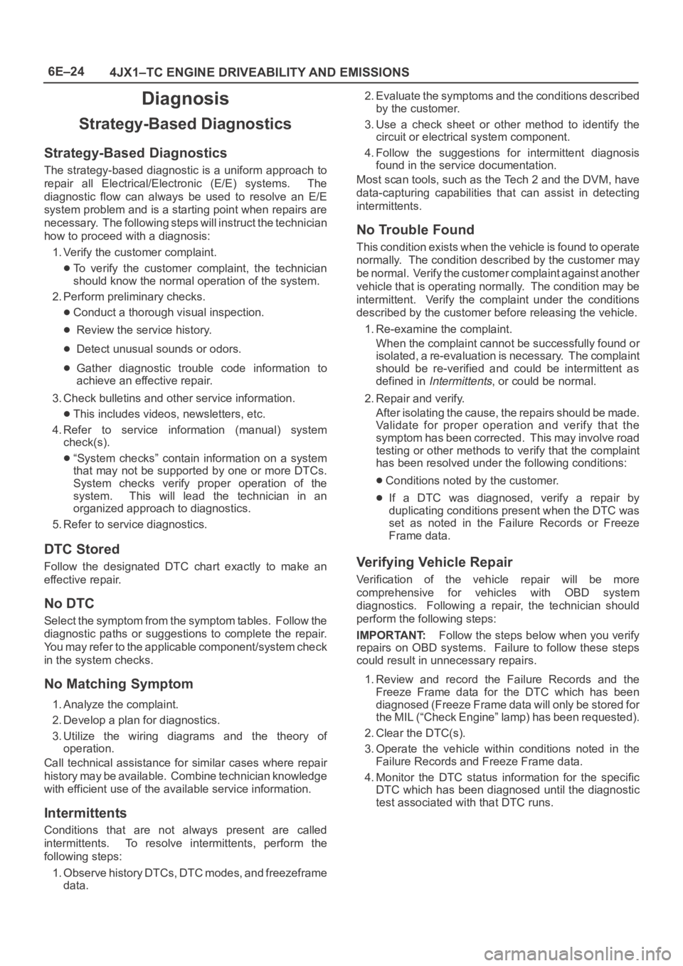
Strategy-Based Diagnostics
Strategy-Based Diagnostics
The strategy-based diagnostic is a uniform approach to
repair all Electrical/Electronic (E/E) systems. The
diagnostic flow can always be used to resolve an E/E
system problem and is a starting point when repairs are
necessary. The following steps will instruct the technician
how to proceed with a diagnosis:
1. Verify the customer complaint.
To verify the customer complaint, the technician
should know the normal operation of the system.
2. Perform preliminary checks.
Conduct a thorough visual inspection.
Review the service history.
Detect unusual sounds or odors.
Gather diagnostic trouble code information to
achieve an effective repair.
3. Check bulletins and other service information.
This includes videos, newsletters, etc.
4. Refer to service information (manual) system
check(s).
“System checks” contain information on a system
that may not be supported by one or more DTCs.
System checks verify proper operation of the
system. This will lead the technician in an
organized approach to diagnostics.
5. Refer to service diagnostics.
DTC Stored
Follow the designated DTC chart exactly to make an
effective repair.
No DTC
Select the symptom from the symptom tables. Follow the
diagnostic paths or suggestions to complete the repair.
You may refer to the applicable component/system check
in the system checks.
No Matching Symptom
1. Analyze the complaint.
2. Develop a plan for diagnostics.
3. Utilize the wiring diagrams and the theory of
operation.
Call technical assistance for similar cases where repair
history may be available. Combine technician knowledge
with efficient use of the available service information.
Intermittents
Conditions that are not always present are called
intermittents. To resolve intermittents, perform the
following steps:
1. Observe history DTCs, DTC modes, and freezeframe
data.2. Evaluate the symptoms and the conditions described
by the customer.
3. Use a check sheet or other method to identify the
circuit or electrical system component.
4. Follow the suggestions for intermittent diagnosis
found in the service documentation.
Most scan tools, such as the Tech 2 and the DVM, have
data-capturing capabilities that can assist in detecting
intermittents.
No Trouble Found
This condition exists when the vehicle is found to operate
normally. The condition described by the customer may
be normal. Verify the customer complaint against another
vehicle that is operating normally. The condition may be
intermittent. Verify the complaint under the conditions
described by the customer before releasing the vehicle.
1. Re-examine the complaint.
When the complaint cannot be successfully found or
isolated, a re-evaluation is necessary. The complaint
should be re-verified and could be intermittent as
defined in
Intermittents, or could be normal.
2. Repair and verify.
After isolating the cause, the repairs should be made.
Validate for proper operation and verify that the
symptom has been corrected. This may involve road
testing or other methods to verify that the complaint
has been resolved under the following conditions:
Conditions noted by the customer.
If a DTC was diagnosed, verify a repair by
duplicating conditions present when the DTC was
set as noted in the Failure Records or Freeze
Frame data.
Verifying Vehicle Repair
Verification of the vehicle repair will be more
comprehensive for vehicles with OBD system
diagnostics. Following a repair, the technician should
perform the following steps:
IMPORTANT:Follow the steps below when you verify
repairs on OBD systems. Failure to follow these steps
could result in unnecessary repairs.
1. Review and record the Failure Records and the
Freeze Frame data for the DTC which has been
diagnosed (Freeze Frame data will only be stored for
the MIL (“Check Engine” lamp) has been requested).
2. Clear the DTC(s).
3. Operate the vehicle within conditions noted in the
Failure Records and Freeze Frame data.
4. Monitor the DTC status information for the specific
DTC which has been diagnosed until the diagnostic
test associated with that DTC runs.
Page 1921 of 6000
6E–28
4JX1–TC ENGINE DRIVEABILITY AND EMISSIONS
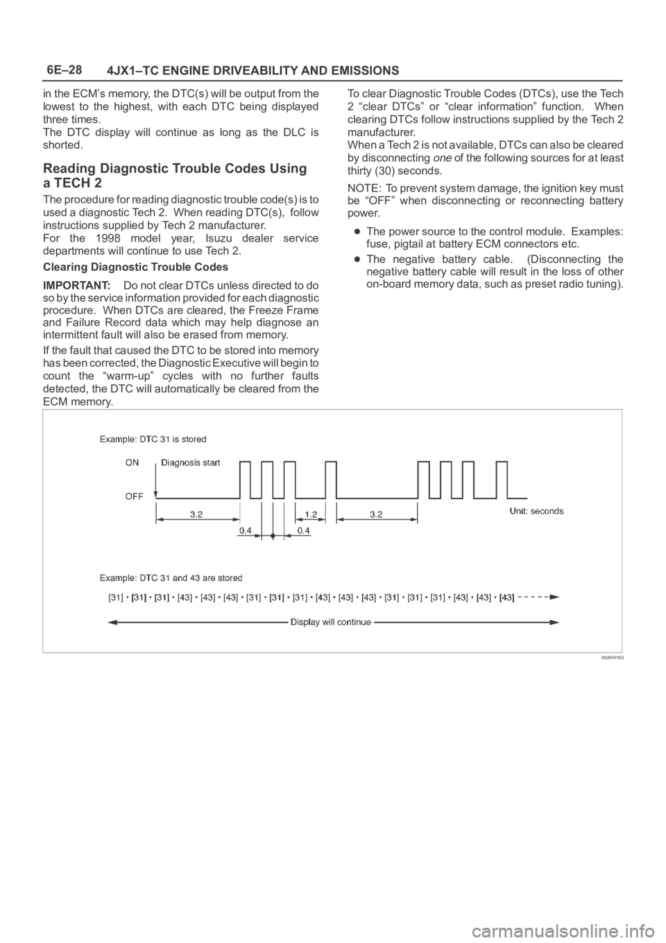
in the ECM’s memory, the DTC(s) will be output from the
lowest to the highest, with each DTC being displayed
three times.
The DTC display will continue as long as the DLC is
shorted.
Reading Diagnostic Trouble Codes Using
a TECH 2
The procedure for reading diagnostic trouble code(s) is to
used a diagnostic Tech 2. When reading DTC(s), follow
instructions supplied by Tech 2 manufacturer.
For the 1998 model year, Isuzu dealer service
departments will continue to use Tech 2.
Clearing Diagnostic Trouble Codes
IMPORTANT:Do not clear DTCs unless directed to do
so by the service information provided for each diagnostic
procedure. When DTCs are cleared, the Freeze Frame
and Failure Record data which may help diagnose an
intermittent fault will also be erased from memory.
If the fault that caused the DTC to be stored into memory
has been corrected, the Diagnostic Executive will begin to
count the “warm-up” cycles with no further faults
detected, the DTC will automatically be cleared from the
ECM memory.To clear Diagnostic Trouble Codes (DTCs), use the Tech
2 “clear DTCs” or “clear information” function. When
clearing DTCs follow instructions supplied by the Tech 2
manufacturer.
When a Tech 2 is not available, DTCs can also be cleared
by disconnecting
one of the following sources for at least
thirty (30) seconds.
NOTE: To prevent system damage, the ignition key must
be “OFF” when disconnecting or reconnecting battery
power.
The power source to the control module. Examples:
fuse, pigtail at battery ECM connectors etc.
The negative battery cable. (Disconnecting the
negative battery cable will result in the loss of other
on-board memory data, such as preset radio tuning).
060RW169
Page 1925 of 6000
6E–32
4JX1–TC ENGINE DRIVEABILITY AND EMISSIONS
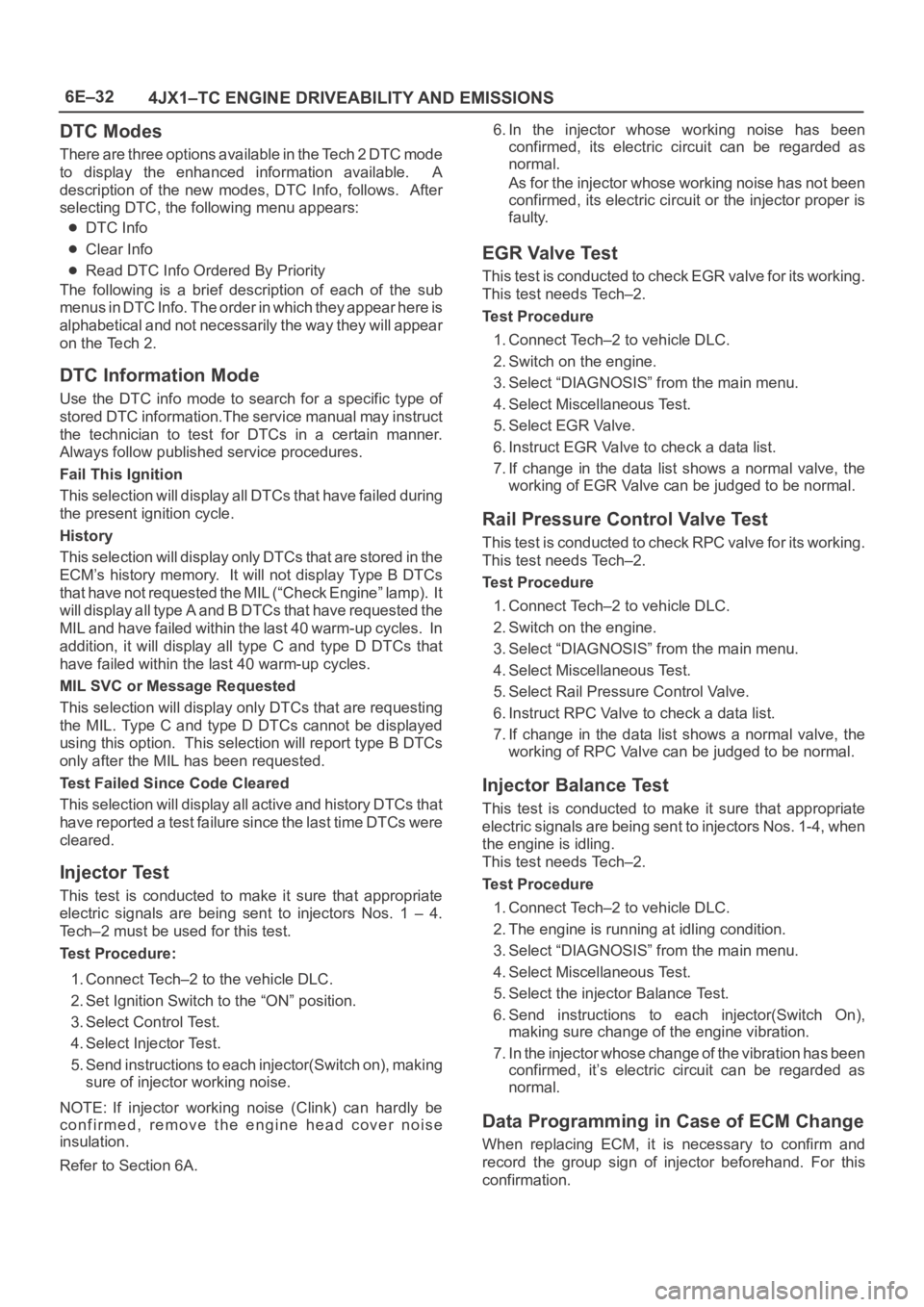
DTC Modes
There are three options available in the Tech 2 DTC mode
to display the enhanced information available. A
description of the new modes, DTC Info, follows. After
selecting DTC, the following menu appears:
DTC Info
Clear Info
Read DTC Info Ordered By Priority
The following is a brief description of each of the sub
menus in DTC Info. The order in which they appear here is
alphabetical and not necessarily the way they will appear
on the Tech 2.
DTC Information Mode
Use the DTC info mode to search for a specific type of
stored DTC information.The service manual may instruct
the technician to test for DTCs in a certain manner.
Always follow published service procedures.
Fail This Ignition
This selection will display all DTCs that have failed during
the present ignition cycle.
History
This selection will display only D T C s t h a t a r e s t o r e d i n t h e
ECM’s history memory. It will not display Type B DTCs
that have not requested the MIL (“Check Engine” lamp). It
will display all type A and B DTCs that have requested the
MIL and have failed within the last 40 warm-up cycles. In
addition, it will display all type C and type D DTCs that
have failed within the last 40 warm-up cycles.
MIL SVC or Message Requested
This selection will display only DTCs that are requesting
the MIL. Type C and type D DTCs cannot be displayed
using this option. This selection will report type B DTCs
only after the MIL has been requested.
Test Failed Since Code Cleared
This selection will display all active and history DTCs that
have reported a test failure since the last time DTCs were
cleared.
Injector Test
This test is conducted to make it sure that appropriate
electric signals are being sent to injectors Nos. 1 – 4.
Tech–2 must be used for this test.
Test Procedure:
1. Connect Tech–2 to the vehicle DLC.
2. Set Ignition Switch to the “ON” position.
3. Select Control Test.
4. Select Injector Test.
5. Send instructions to each injector(Switch on), making
sure of injector working noise.
NOTE: If injector working noise (Clink) can hardly be
confirmed, remove the engine head cover noise
insulation.
Refer to Section 6A.6. In the injector whose working noise has been
confirmed, its electric circuit can be regarded as
normal.
As for the injector whose working noise has not been
confirmed, its electric circuit or the injector proper is
faulty.
EGR Valve Test
This test is conducted to check EGR valve for its working.
This test needs Tech–2.
Test Procedure
1. Connect Tech–2 to vehicle DLC.
2. Switch on the engine.
3. Select “DIAGNOSIS” from the main menu.
4. Select Miscellaneous Test.
5. Select EGR Valve.
6. Instruct EGR Valve to check a data list.
7. If change in the data list shows a normal valve, the
working of EGR Valve can be judged to be normal.
Rail Pressure Control Valve Test
This test is conducted to check RPC valve for its working.
This test needs Tech–2.
Test Procedure
1. Connect Tech–2 to vehicle DLC.
2. Switch on the engine.
3. Select “DIAGNOSIS” from the main menu.
4. Select Miscellaneous Test.
5. Select Rail Pressure Control Valve.
6. Instruct RPC Valve to check a data list.
7. If change in the data list shows a normal valve, the
working of RPC Valve can be judged to be normal.
Injector Balance Test
This test is conducted to make it sure that appropriate
electric signals are being sent to injectors Nos. 1-4, when
the engine is idling.
This test needs Tech–2.
Test Procedure
1. Connect Tech–2 to vehicle DLC.
2. The engine is running at idling condition.
3. Select “DIAGNOSIS” from the main menu.
4. Select Miscellaneous Test.
5. Select the injector Balance Test.
6. Send instructions to each injector(Switch On),
making sure change of the engine vibration.
7. In the injector whose change of the vibration has been
confirmed, it’s electric circuit can be regarded as
normal.
Data Programming in Case of ECM Change
When replacing ECM, it is necessary to confirm and
record the group sign of injector beforehand. For this
confirmation.
Page 2078 of 6000
6E–185 4JX1–TC ENGINE DRIVEABILITY AND EMISSIONS
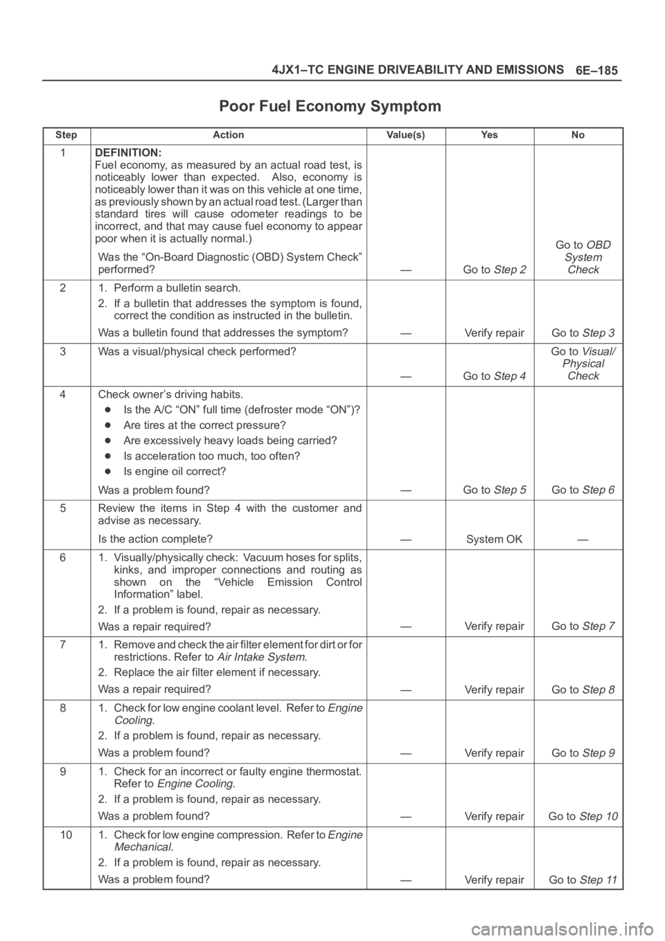
Poor Fuel Economy Symptom
StepActionVa l u e ( s )Ye sNo
1DEFINITION:
Fuel economy, as measured by an actual road test, is
noticeably lower than expected. Also, economy is
noticeably lower than it was on this vehicle at one time,
as previously shown by an actual road test. (Larger than
standard tires will cause odometer readings to be
incorrect, and that may cause fuel economy to appear
poor when it is actually normal.)
Was the “On-Board Diagnostic (OBD) System Check”
performed?
—Go to Step 2
Go to OBD
System
Check
21. Perform a bulletin search.
2. If a bulletin that addresses the symptom is found,
correct the condition as instructed in the bulletin.
Was a bulletin found that addresses the symptom?
—Verify repairGo to Step 3
3Was a visual/physical check performed?
—Go to Step 4
Go to Visual/
Physical
Check
4Check owner’s driving habits.
Is the A/C “ON” full time (defroster mode “ON”)?
Are tires at the correct pressure?
Are excessively heavy loads being carried?
Is acceleration too much, too often?
Is engine oil correct?
Was a problem found?
—Go to Step 5Go to Step 6
5Review the items in Step 4 with the customer and
advise as necessary.
Is the action complete?
—System OK—
61. Visually/physically check: Vacuum hoses for splits,
kinks, and improper connections and routing as
shown on the “Vehicle Emission Control
Information” label.
2. If a problem is found, repair as necessary.
Was a repair required?
—Verify repairGo to Step 7
71. Remove and check the air filter element for dirt or for
restrictions. Refer to
Air Intake System.
2. Replace the air filter element if necessary.
Was a repair required?
—Verify repairGo to Step 8
81. Check for low engine coolant level. Refer to Engine
Cooling
.
2. If a problem is found, repair as necessary.
Was a problem found?
—Verify repairGo to Step 9
91. Check for an incorrect or faulty engine thermostat.
Refer to
Engine Cooling.
2. If a problem is found, repair as necessary.
Was a problem found?
—Verify repairGo to Step 10
101. Check for low engine compression. Refer to Engine
Mechanical
.
2. If a problem is found, repair as necessary.
Was a problem found?
—Verify repairGo to Step 11
Page 2153 of 6000

6J – 12 INDUCTION
INSPECTION AND RAPAIR
1. Visually check for cracks/clogs inside intake
manifold.
2. If foreign material is observed, it should be taken
out, and if there are some cracks on the intake
manifold, it must be replaced.
INSTALLATION
1. Install the intake manifold assembly, tighten bolts
and to the specified torque.
Torque: 20 Nꞏm (2.0 kgꞏm / 14.5 lb ft) for bolt
Torque: 20 Nꞏm (2.0 kgꞏm / 14.5 lb ft) for nut
2. Install fuel pipe.
Torque: 4 Nꞏm (0.4 kgꞏm / 2.9 lb ft) for M16 nut
(Apply engine oil)
Torque: 13 Nꞏm (1.3 kgꞏm / 9.4 lb ft) for M10 cap nut
Torque: 14 Nꞏm (1.4 kgꞏm / 10 lb ft) for M10
(Apply engine oil)
3. Install two way check valve.
Torque: 20 Nꞏm (2.0 kgꞏm / 14.5 lb ft)
4. Fill with about 300 cc of engine oil from the high
pressure oil pipe installation port of the oil rail using
an oil filler.
If assembled without filling the oil rail with oil, the
time for engine starting will be longer.
5. Install high pressure oil pipe, then tighten sleeve nut
to the specified torque.
Torque: 29 Nꞏm (3.0 kgꞏm / 21.7 lb ft)
6. Reconnect harness connector to MAP sensor, EGR
vacuum sensor, ETC sensor, Water thermo unit,
IAT sensor and EVRV sensor.
7. Install hoses to EGR valve, EGR vacuum sensor
and Water outlet of heater.
8. Connect PCV hose.
9. Install oil level gauge guide and fix it.
10. Install intercooler assembly.
Refer to “Intercooler” in this manual.
11. Install water hose to thermostat housing and fill with
engine coolant.
Model of Turbocharger IHI RHF5
Turbine Maximum Speed 180,000 rpm
Maximum Inlet Gas Temperature 800 °C (1472 °F)
Vibration Peak (G) criteria Maximum 4 (G) at Turbine Rotor Speed 140,000 rpm
Tolerance Limit of Compressor Blade Height Less then 0.5 mm (0.0197 in)
MAIN DATA AND SPECIFICATIONS
Page 2173 of 6000
7A–19 AUTOMATIC TRANSMISSION (4L30–E)
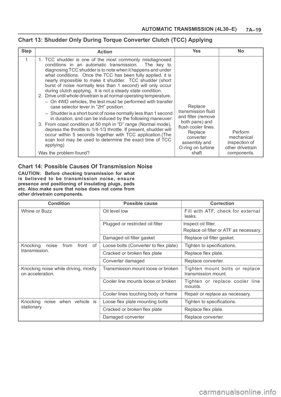
Chart 13: Shudder Only During Torque Converter Clutch (TCC) Applying
StepActionYe sNo
11. TCC shudder is one of the most commonly misdiagnosed
conditions in an automatic transmission. The key to
diagnosing TCC shudder is to note when it happens and under
what conditions. Once the TCC has been fully applied, it is
nearly impossible to make it shudder. TCC shudder (short
burst of noise normally less than 1 second) will only occur
during clutch applying. It is not a steady state condition.
2. Drive until whole drivetrain is at normal operating temperature.
– On 4WD vehicles, the test must be performed with transfer
case selector lever in “2H” position.
– Shudder is a short burst of noise normally less than 1 second
in duration, and can be induced by the following maneuver:
3. From coast condition at 50 mph in “D” range (Normal mode),
depress the throttle to 1/4-1/3 throttle. If present, shudder will
occur within 5 seconds together with TCC application.(The
scan tool may be used to determine the exact time of TCC
applying)
Was the problem found?
Replace
transmission fluid
and filter (remove
both pans) and
flush cooler lines.
Replace
converter
assembly and
O-ring on turbine
shaft
Perform
mechanical
inspection of
other drivetrain
components.
Chart 14: Possible Causes Of Transmission Noise
CAUTION: Before checking transmission for what
is believed to be transmission noise, ensure
presence and positioning of insulating plugs, pads
etc. Also make sure that noise does not come from
other drivetrain components.
Condition
Possible causeCorrection
Whine or BuzzOil level lowFill with ATF, check for external
leaks.
Plugged or restricted oil filterInspect oil filter.
Replace oil filter or ATF as necessary.
Damaged oil filter gasketReplace oil filter gasket.
Knocking noise from front of
transmission
Loose bolts (Converter to flex plate)Tighten to specifications.
transmission.Cracked or broken flex plateReplace flex plate.
Converter damagedReplace converter.
Knocking noise while driving, mostly
on acceleration.Transmission mount loose or brokenTighten mount bolts or replace
transmission mount.
Cooler line mounts loose or brokenTighten or replace cooler line
mounts.
Cooler lines touching body or frameRepair or replace as necessary.
Knocking noise when vehicle is
stationary
Loose flex plate mounting boltsTighten to specifications.
stationary.Cracked or broken flex plateReplace flex plate.
Damaged converterReplace converter.
Page 2178 of 6000
7A–24
AUTOMATIC TRANSMISSION (4L30–E)
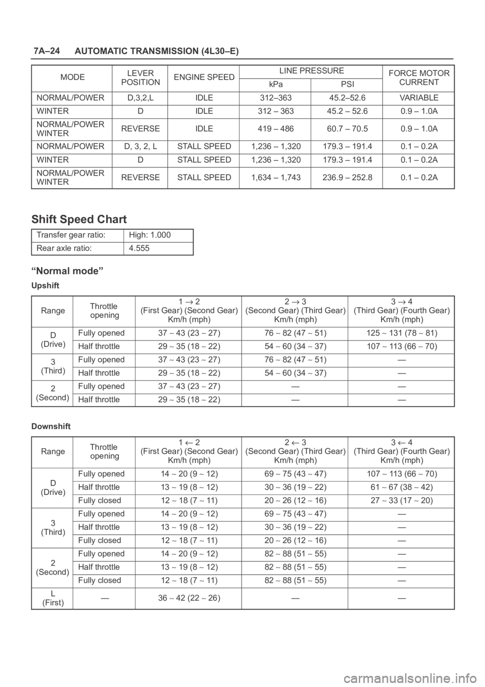
MODELEVERENGINE SPEEDLINE PRESSUREFORCE MOTORMODEPOSITIONENGINE SPEEDkPaPSICURRENT
NORMAL/POWERD,3,2,LIDLE312–36345.2–52.6VA R I A B L E
WINTERDIDLE312 – 36345.2 – 52.60.9 – 1.0A
NORMAL/POWER
WINTERREVERSEIDLE419 – 48660.7 – 70.50.9 – 1.0A
NORMAL/POWERD, 3, 2, LSTALL SPEED1,236 – 1,320179.3 – 191.40.1 – 0.2A
WINTERDSTALL SPEED1,236 – 1,320179.3 – 191.40.1 – 0.2A
NORMAL/POWER
WINTERREVERSESTALL SPEED1,634 – 1,743236.9 – 252.80.1 – 0.2A
Shift Speed Chart
Transfer gear ratio:High: 1.000
Rear axle ratio:4.555
“Normal mode”
Upshift
Range
Throttle
opening1 2
(First Gear) (Second Gear)
Km/h (mph)2 3
(Second Gear) (Third Gear)
Km/h (mph)3 4
(Third Gear) (Fourth Gear)
Km/h (mph)
DFully opened37 43 (23 27)76 82 (47 51)125 131 (78 81)
(Drive)Half throttle29 35 (18 22)54 60 (34 37)107 113 (66 70)
3Fully opened37 43 (23 27)76 82 (47 51)—
(Third)Half throttle29 35 (18 22)54 60 (34 37)—
2Fully opened37 43 (23 27)——
(Second)Half throttle29 35 (18 22)——
Downshift
Range
Throttle
opening1 2
(First Gear) (Second Gear)
Km/h (mph)2 3
(Second Gear) (Third Gear)
Km/h (mph)3 4
(Third Gear) (Fourth Gear)
Km/h (mph)
D
Fully opened14 20 (9 12)69 75 (43 47)107 113 (66 70)
D
(Drive)Half throttle13 19 (8 12)30 36 (19 22)61 67 (38 42)(Drive)
Fully closed12 18 (7 11)20 26 (12 16)27 33 (17 20)
3
Fully opened14 20 (9 12)69 75 (43 47)—
3
(Third)Half throttle13 19 (8 12)30 36 (19 22)—(Third)
Fully closed12 18 (7 11)20 26 (12 16)—
2
Fully opened14 20 (9 12)82 88 (51 55)—
2
(Second)Half throttle13 19 (8 12)82 88 (51 55)—(Second)
Fully closed12 18 (7 11)82 88 (51 55)—
L
(First)—36 42 (22 26)——
Page 2179 of 6000
7A–25 AUTOMATIC TRANSMISSION (4L30–E)
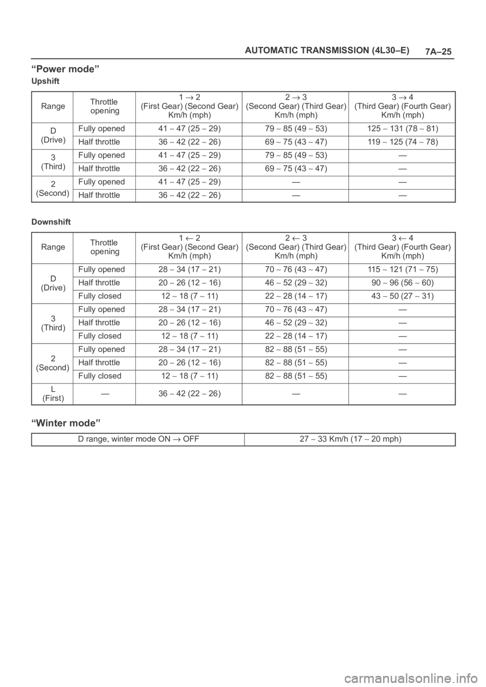
“Power mode”
Upshift
Range
Throttle
opening1 2
(First Gear) (Second Gear)
Km/h (mph)2 3
(Second Gear) (Third Gear)
Km/h (mph)3 4
(Third Gear) (Fourth Gear)
Km/h (mph)
DFully opened41 47 (25 29)79 85 (49 53)125 131 (78 81)
(Drive)Half throttle36 42 (22 26)69 75 (43 47)11 9 125 (74 78)
3Fully opened41 47 (25 29)79 85 (49 53)—
(Third)Half throttle36 42 (22 26)69 75 (43 47)—
2Fully opened41 47 (25 29)——
(Second)Half throttle36 42 (22 26)——
Downshift
Range
Throttle
opening1 2
(First Gear) (Second Gear)
Km/h (mph)2 3
(Second Gear) (Third Gear)
Km/h (mph)3 4
(Third Gear) (Fourth Gear)
Km/h (mph)
D
Fully opened28 34 (17 21)70 76 (43 47)11 5 121 (71 75)
D
(Drive)Half throttle20 26 (12 16)46 52 (29 32)90 96 (56 60)(Drive)
Fully closed12 18 (7 11)22 28 (14 17)43 50 (27 31)
3
Fully opened28 34 (17 21)70 76 (43 47)—
3
(Third)Half throttle20 26 (12 16)46 52 (29 32)—(Third)
Fully closed12 18 (7 11)22 28 (14 17)—
2
Fully opened28 34 (17 21)82 88 (51 55)—
2
(Second)Half throttle20 26 (12 16)82 88 (51 55)—(Second)
Fully closed12 18 (7 11)82 88 (51 55)—
L
(First)—36 42 (22 26)——
“Winter mode”
D range, winter mode ON OFF27 33 Km/h (17 20 mph)