1998 OPEL FRONTERA ECO mode
[x] Cancel search: ECO modePage 2999 of 6000

8D–406 WIRING SYSTEM
There are four kinds of ID codes which can be registered,
for which these three modes, ID code new registration, ID
code additional registration and ID code check, are
available.
This procedure erases all registered ID codes and
registers a new received ID code instead.
Step Action Yes No
1. Open the driver’s side door.
2. Turn the starter switch off.
Is the action complete?
Turn the starter switch to ACC position and then off three times
within five seconds after step 1.
Is the action complete within five seconds?
Close the door and then open it two times within ten seconds after
step 2.
Is the action complete within ten seconds?
1. Turn the starter switch to ACC position and then off five times.
2. Close the door and then open it.
NOTE: This step must be performed within ten seconds after step
3.
Is the action complete?
The control unit makes lock/unlock response once with interval of
one second.
Is the response complete?
Operate the lock or unlock button of transmitter within twenty
seconds after step 5.
Is the action complete?
The control unit makes lock/unlock response once with interval of
one second as ID temporary registration.
Is the response complete?
Operate the lock or unlock button of transmitter within twenty
seconds after step 7.
Is the action complete?
The control unit compares temporary registered ID code with
receiving ID code.
Is temporary registered ID code the same as receiving ID code?
The control unit makes lock/unlock response three times with
interval of one second.
Is the response complete?
The control unit erases all registered ID codes and registers new
ID code.
Is the registration complete? 1
2
3
4
5
6
7
8
9
10
11Go to Step 2
Go to Step 3
Go to Step 4
Go to Step 5
Go to Step 6
Go to Step 7
Go to Step 8
Go to Step 9
Go to Step 11
Finished
Go to Step 12—
Finished
Finished
Finished
—
Finished
—
Finished
Go to Step 11
—
Go to Step 13
Page 3002 of 6000
WIRING SYSTEM 8D–409
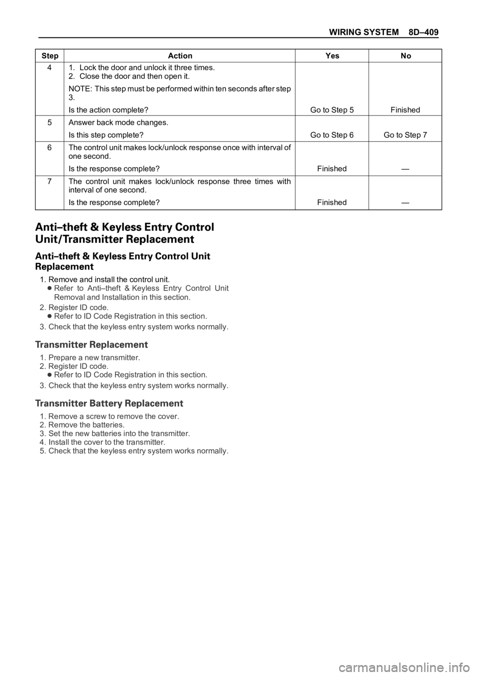
Step Action Yes No
1. Lock the door and unlock it three times.
2. Close the door and then open it.
NOTE: This step must be performed within ten seconds after step
3.
Is the action complete?
Answer back mode changes.
Is this step complete?
The control unit makes lock/unlock response once with interval of
one second.
Is the response complete?
The control unit makes lock/unlock response three times with
interval of one second.
Is the response complete? 4
5
6
7Go to Step 5
Go to Step 6
Finished
FinishedFinished
Go to Step 7
—
—
1. Remove and install the control unit.
Refer to Anti–theft & Keyless Entry Control Unit
Removal and Installation in this section.
2. Register ID code.
Refer to ID Code Registration in this section.
3. Check that the keyless entry system works normally.
1. Prepare a new transmitter.
2. Register ID code.
Refer to ID Code Registration in this section.
3. Check that the keyless entry system works normally.
1. Remove a screw to remove the cover.
2. Remove the batteries.
3. Set the new batteries into the transmitter.
4. Install the cover to the transmitter.
5. Check that the keyless entry system works normally.
Page 3363 of 6000
8H–24SECURITY AND LOCKS
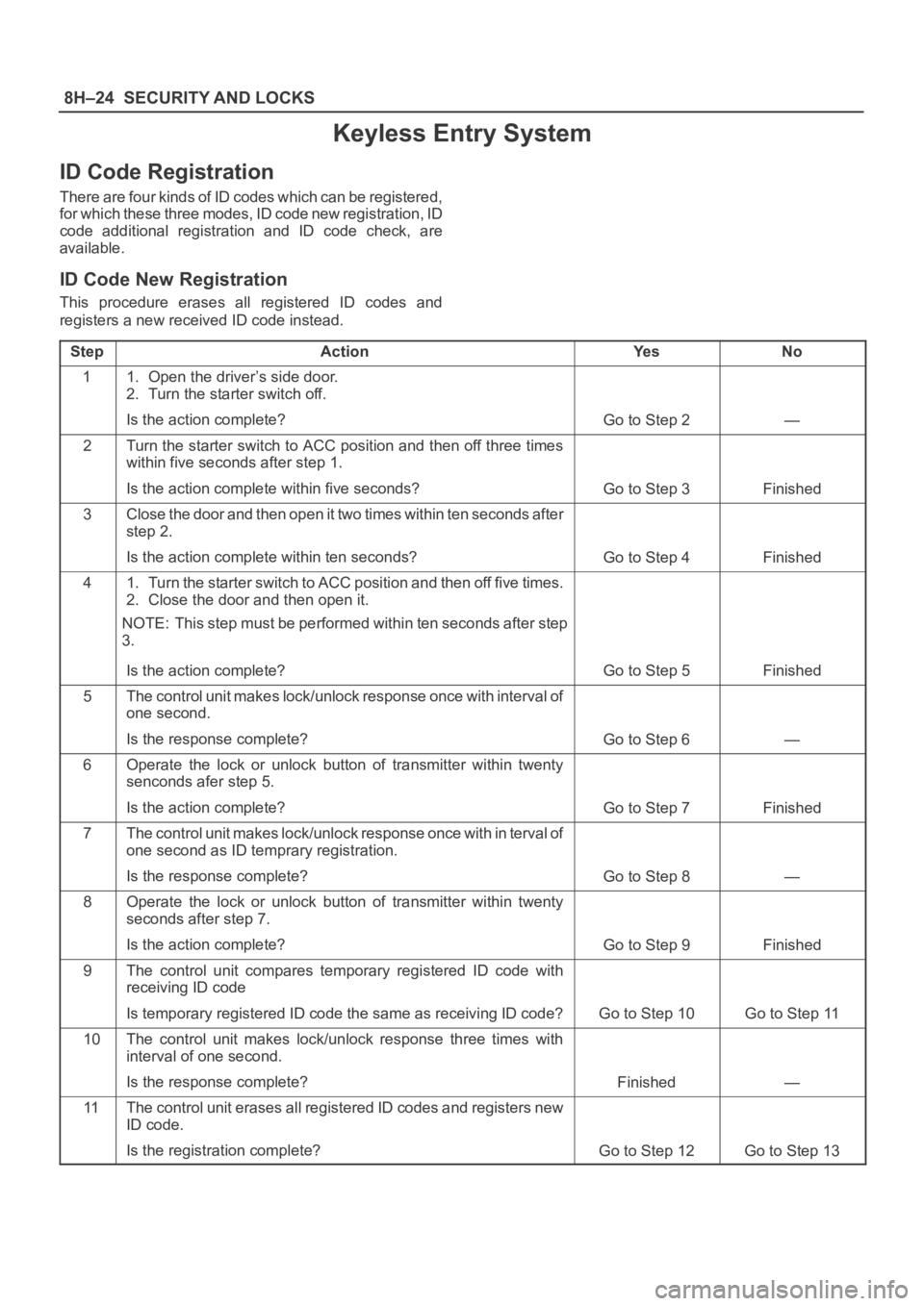
Keyless Entry System
ID Code Registration
There are four kinds of ID codes which can be registered,
for which these three modes, ID code new registration, ID
code additional registration and ID code check, are
available.
ID Code New Registration
This procedure erases all registered ID codes and
registers a new received ID code instead.
Step
ActionYe sNo
11. Open the driver’s side door.
2. Turn the starter switch off.
Is the action complete?
Go to Step 2—
2Turn the starter switch to ACC position and then off three times
within five seconds after step 1.
Is the action complete within five seconds?
Go to Step 3Finished
3Close the door and then open it two times within ten seconds after
step 2.
Is the action complete within ten seconds?
Go to Step 4Finished
41. Turn the starter switch to ACC position and then off five times.
2. Close the door and then open it.
NOTE: This step must be performed within ten seconds after step
3.
Is the action complete?
Go to Step 5Finished
5The control unit makes lock/unlock response once with interval of
one second.
Is the response complete?
Go to Step 6—
6Operate the lock or unlock button of transmitter within twenty
senconds afer step 5.
Is the action complete?
Go to Step 7Finished
7The control unit makes lock/unlock response once with in terval o f
one second as ID temprary registration.
Is the response complete?
Go to Step 8—
8Operate the lock or unlock button of transmitter within twenty
seconds after step 7.
Is the action complete?
Go to Step 9Finished
9The control unit compares temporary registered ID code with
receiving ID code
Is temporary registered ID code the same as receiving ID code?
Go to Step 10Go to Step 11
10The control unit makes lock/unlock response three times with
interval of one second.
Is the response complete?
Finished—
11The control unit erases all registered ID codes and registers new
ID code.
Is the registration complete?
Go to Step 12Go to Step 13
Page 3365 of 6000
8H–26SECURITY AND LOCKS
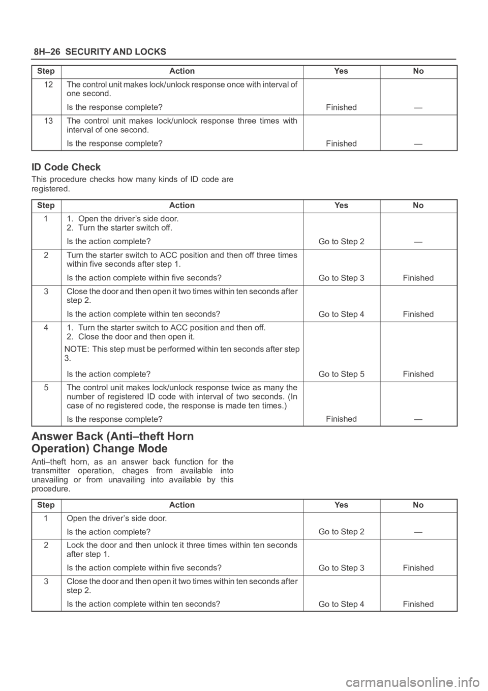
StepNo Ye s Action
12The control unit makes lock/unlock response once with interval of
one second.
Is the response complete?
Finished—
13The control unit makes lock/unlock response three times with
interval of one second.
Is the response complete?
Finished—
ID Code Check
This procedure checks how many kinds of ID code are
registered.
Step
ActionYe sNo
11. Open the driver’s side door.
2. Turn the starter switch off.
Is the action complete?
Go to Step 2—
2Turn the starter switch to ACC position and then off three times
within five seconds after step 1.
Is the action complete within five seconds?
Go to Step 3Finished
3Close the door and then open it two times within ten seconds after
step 2.
Is the action complete within ten seconds?
Go to Step 4Finished
41. Turn the starter switch to ACC position and then off.
2. Close the door and then open it.
NOTE: This step must be performed within ten seconds after step
3.
Is the action complete?
Go to Step 5Finished
5The control unit makes lock/unlock response twice as many the
number of registered ID code with interval of two seconds. (In
case of no registered code, the response is made ten times.)
Is the response complete?
Finished—
Answer Back (Anti–theft Horn
Operation) Change Mode
Anti–theft horn, as an answer back function for the
transmitter operation, chages from available into
unavailing or from unavailing into available by this
procedure.
Step
ActionYe sNo
1Open the driver’s side door.
Is the action complete?
Go to Step 2—
2Lock the door and then unlock it three times within ten seconds
after step 1.
Is the action complete within five seconds?
Go to Step 3Finished
3Close the door and then open it two times within ten seconds after
step 2.
Is the action complete within ten seconds?
Go to Step 4Finished
Page 3366 of 6000
SECURITY AND LOCKS8H–27
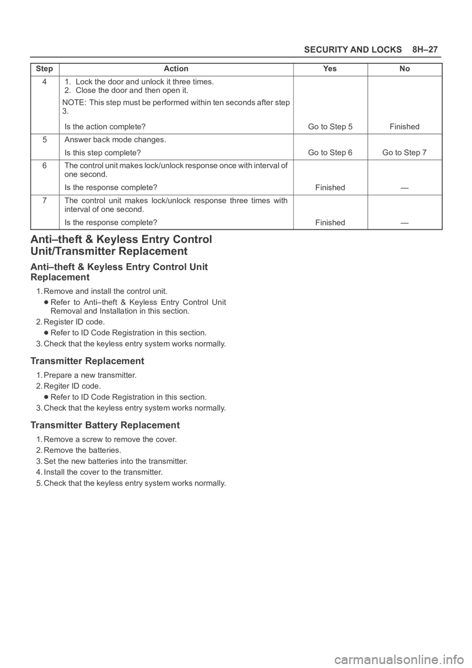
StepNo Ye s Action
41. Lock the door and unlock it three times.
2. Close the door and then open it.
NOTE: This step must be performed within ten seconds after step
3.
Is the action complete?
Go to Step 5Finished
5Answer back mode changes.
Is this step complete?
Go to Step 6Go to Step 7
6The control unit makes lock/unlock response once with interval of
one second.
Is the response complete?
Finished—
7The control unit makes lock/unlock response three times with
interval of one second.
Is the response complete?
Finished—
Anti–theft & Keyless Entry Control
Unit/Transmitter Replacement
Anti–theft & Keyless Entry Control Unit
Replacement
1. Remove and install the control unit.
Refer to Anti–theft & Keyless Entry Control Unit
Removal and Installation in this section.
2. Register ID code.
Refer to ID Code Registration in this section.
3. Check that the keyless entry system works normally.
Transmitter Replacement
1. Prepare a new transmitter.
2. Regiter ID code.
Refer to ID Code Registration in this section.
3. Check that the keyless entry system works normally.
Transmitter Battery Replacement
1. Remove a screw to remove the cover.
2. Remove the batteries.
3. Set the new batteries into the transmitter.
4. Install the cover to the transmitter.
5. Check that the keyless entry system works normally.
Page 3465 of 6000
SUPPLEMENTAL RESTRAINT SYSTEM 9J–28
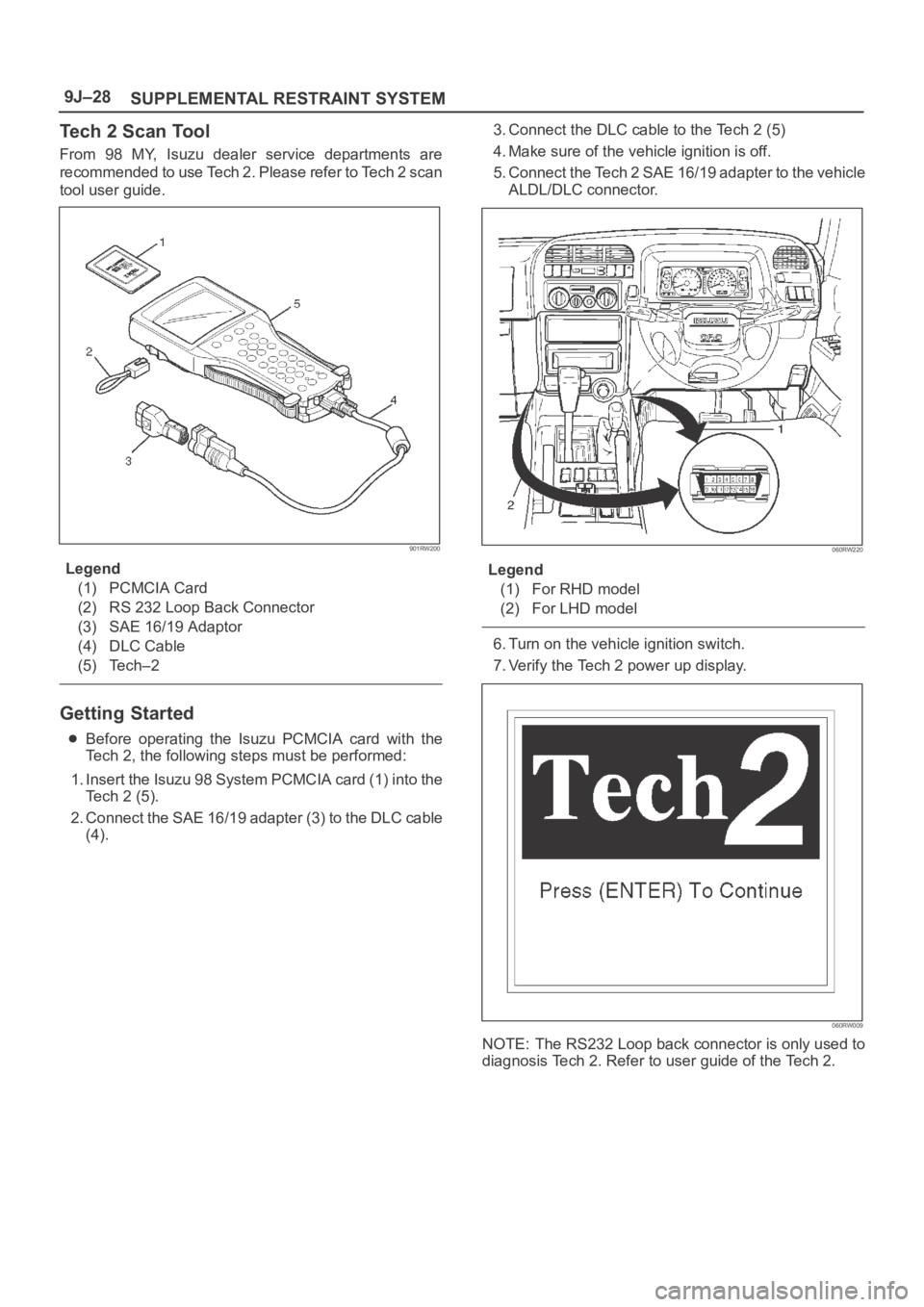
Tech 2 Scan Tool
From 98 MY, Isuzu dealer service departments are
recommended to use Tech 2. Please refer to Tech 2 scan
tool user guide.
901RW200
Legend
(1) PCMCIA Card
(2) RS 232 Loop Back Connector
(3) SAE 16/19 Adaptor
(4) DLC Cable
(5) Tech–2
Getting Started
Before operating the Isuzu PCMCIA card with the
Tech 2, the following steps must be performed:
1. Insert the Isuzu 98 System PCMCIA card (1) into the
Tech 2 (5).
2. Connect the SAE 16/19 adapter (3) to the DLC cable
(4).3. Connect the DLC cable to the Tech 2 (5)
4. Make sure of the vehicle ignition is off.
5. Connect the Tech 2 SAE 16/19 adapter to the vehicle
ALDL/DLC connector.
060RW220
Legend
(1) For RHD model
(2) For LHD model
6. Turn on the vehicle ignition switch.
7. Verify the Tech 2 power up display.
060RW009
NOTE: The RS232 Loop back connector is only used to
diagnosis Tech 2. Refer to user guide of the Tech 2.
Page 3489 of 6000
RESTRAINT CONTROL SYSTEM 9J1–2
Diagnostic Information
CAUTION: When fasteners are removed, always
reinstall them at the same location from which they
were removed. if a fastener needs to be replaced, use
the correct part number fastener for that application.
if the correct part number fastener is not available, a
fastener of equal size and strength (or stronger) may
be used. fasteners that are not reused, and those
requiring thread locking compound will be called
out. the correct torque value must be used when
installing fasteners that require it. if the above
conditions are not followed, parts or system damage
could result.
Diagnostic Procedures
WARNING: TO AVOID DEPLOYMENT WHEN
TROUBLESHOOTING THE SRS, DO NOT USE
ELECTRICAL TEST EQUIPMENT SUCH AS A
BATTERY–POWERED OR AC–POWERED
VOLTMETER, OHMMETER, ETC., OR ANY TYPE OF
ELECTRICAL EQUIPMENT OTHER THAN THAT
SPECIFIED IN THIS MANUAL. DO NOT USE A NON
POWERED, PROBE–TYPE TESTER.
INSTRUCTIONS IN THIS MANUAL MUST BE
FOLLOWED CAREFULLY, OTHERWISE PERSONAL
INJURY MAY RESULT.
The diagnostic procedures used in this section are
designed to aid in finding and repairing SRS problems.
Outlined below are the steps to find and repair SRS
problems quickly and effectively. Failure to carefully
follow these procedures may result in extended
diagnostic time, incorrect diagnosis and incorrect parts
replacement.
1.Perform The “SRS Diagnostic System Check”.
The “SRS Diagnostic System Check” should always
be the starting point of any SRS diagnostics. The
“SRS Diagnostic System Check” checks for proper
“AIR BAG” warning lamp operation and checks for
SRS trouble codes using both “Flash Code” and
“Scan Tool” Methods.
2.Refer To The Proper Diagnostic Chart As Directed
By The “SRS Diagnostic System Check”.
The “SRS Diagnostic System Check” will lead you to
the correct chart to diagnose any SRS problems.
Bypassing these procedures may result in extended
diagnostic time, incorrect diagnosis and incorrect
parts replacement.
3.Repeat The “SRS Diagnostic System Check”
After Any Repair Or Diagnostic Procedures Have
Been Performed.
Preforming the “SRS Diagnostic System Check” after
all repair or diagnostic procedures will assure that the
repair has been made correctly and that no other
conditions exist.
Diagnostic Codes
The Sensing and Diagnostic Module (SDM) maintains a
history record of all diagnostic codes that have beendetected since the SRS codes were last cleared during
service.
1. Active Codes — Faults that are presently detected
this ignition cycle. Active codes are stored in RAM
(Random Access Memory).
2. History Codes — All faults detected since the last
time the history fault memory was cleared. History
codes are stored in EEPROM. (Electronically
Erasable Programmable Read only Memory)
How To Read Trouble Codes
All codes (Active and history) can be read (or cleared) by
using a scan tool or equivalent.
If a PDT is not available, have the vehicle serviced by
ISUZU dealer.
How To Clear Trouble Codes
Trouble codes can only be cleared by using a Scan Tool.
If a “scan tool” is not available then inform the owner of the
stored codes and suggest that the codes are cleared
upon the next visit to an Isuzu dealership.
Scan Tool Diagnostics
A scan tool can be used to read current and history codes
and to clear all history codes after a repair is complete.
The scan tool must be updated to communicate with the
SRS through a memory card or a manufacturer’s update
before it can be used for SRS diagnostics. To use the
scan tool, connect it to the DLC connector and turn the
ignition switch “ON”. Then follow the manufacturer’s
directions for communication with the SRS. The scan tool
reads serial data from the SDM “Serial Data” output
(terminal 24) to the DLC connector (terminal 9).
Basic Knowledge Required
Before using this section of the Service Manual, there is
some basic knowledge which will be required. Without
this knowledge, you will have trouble using the diagnostic
procedures in this section. Use care to prevent harm or
unwanted deployment. Read all cautions in the service
manual and on warning labels attached to SRS
components.
Basic Electrical Circuits
You should understand the basic theory of electricity
including series and parallel circuits, and understand the
voltage drops across series resistors. You should know
the meaning of voltage (volts), current (amps), and
resistance (ohms). You should understand what happens
in a circuit with an open or a shorted wire. You should be
able to read and understand a wiring diagram.
“Flash Code” Diagnostics
Flash code diagnostics can be used to read active codes
and to determine if history codes are present but cannot
be used to clear codes or read history codes. Flash code
diagnostics is enabled by grounding by terminal 4
shorting to terminal 13 of the DLC connector with the
ignition switch “ON”. Grounding terminal 4 of the DLC
connector pulls the “Diagnostics Request” input (Terminal
1) of the SDM low and signals the SDM to enter the flash
code diagnostic display mode.
Page 3490 of 6000
9J1–3
RESTRAINT CONTROL SYSTEM
The SDM displays the trouble codes by flashing the
warning lamp. Each code that is displayed will consist of a
number of flashes which represents the tens digit, a 1.2
second pause, following by a number of flashes which
represents the ones digit of the code. Each code is
displayed one time before moving on to the next code.
After all of the codes have been displayed, the entire code
sequence will continually by repeated until ground is
removed from terminal 4 of the DLC connector.
Two special codes exist when reading in the flash code
mode (Flash Code 12 and Flash Code 13). “Flash Code
12“ will always be the first code displayed when the flash
code mode is enable Code 12 is not an indication of a SRS
problem but an indication that the flash code mode has
been enabled. If there are no active or history codes
present, the SDM will display code 12 until ground is
removed from the DLC connector at terminal 4. “flash
Code 13” will be displayed if history codes are present. To
read the history codes a scan tool must be used.