1998 OPEL FRONTERA battery
[x] Cancel search: batteryPage 4824 of 6000
6E–167 ENGINE DRIVEABILITY AND EMISSIONS
Barometric pressure is greater than 72.5 kPa.
Mass air flow is between 2 g/second and 200 g/second.
Ignition voltage is above 9.5 volts.
Fuel system is in “closed loop.”
Action Taken When the DTC Sets
The PCM will illuminate the malfunction indicator lamp
(MIL) after the second consecutive trip in which the
failure is detected.
The PCM will store conditions which were present
when the DTC was set as Freeze Frame and in the
Failure Records data.
Conditions for Clearing the MIL/DTC
DTC P0175 can be cleared by using the Tech 2 “Clear
Info” function or by disconnecting the PCM battery
feed.
Diagnostic Aids
Check for the following conditions:
Poor connection at PCM – Inspect harness connectors
for backed -out terminals, improper mating, broken
locks, improperly formed or damaged terminals, and
poor terminal-to-wire connection.
Damaged harness – Inspect the wiring harness for
damage. If the harness appears to be OK, observe the
Bank 2 HO2S 1 display on the Tech 2 while moving
connectors and wiring harnesses related to the engine
harness. A change in the display will indicate the
location of the fault.
Reviewing the Failure Records Vehicle mileage since the
diagnostic test last failed may help determine how often
the condition that caused the DTC to be set occurs. This
may assist in diagnosing the condition.
Test Description
Number(s) below refer to the step number(s) on the
Diagnostic Chart.
2. DTCs other than P0172 and P0175 may indicate a
condition present which may cause a lean condition.
If this is the case, repairing the condition which
caused the other DTC will most likely correct the
DTC P0172/P0175.
4. If the DTC P0175 test passes while the Failure
Records conditions are being duplicated, the rich
condition is intermittent. Refer to
Diagnostic Aids or
Symptoms for additional information on diagnosing
intermittent problems.
Page 4827 of 6000
6E–170
ENGINE DRIVEABILITY AND EMISSIONS
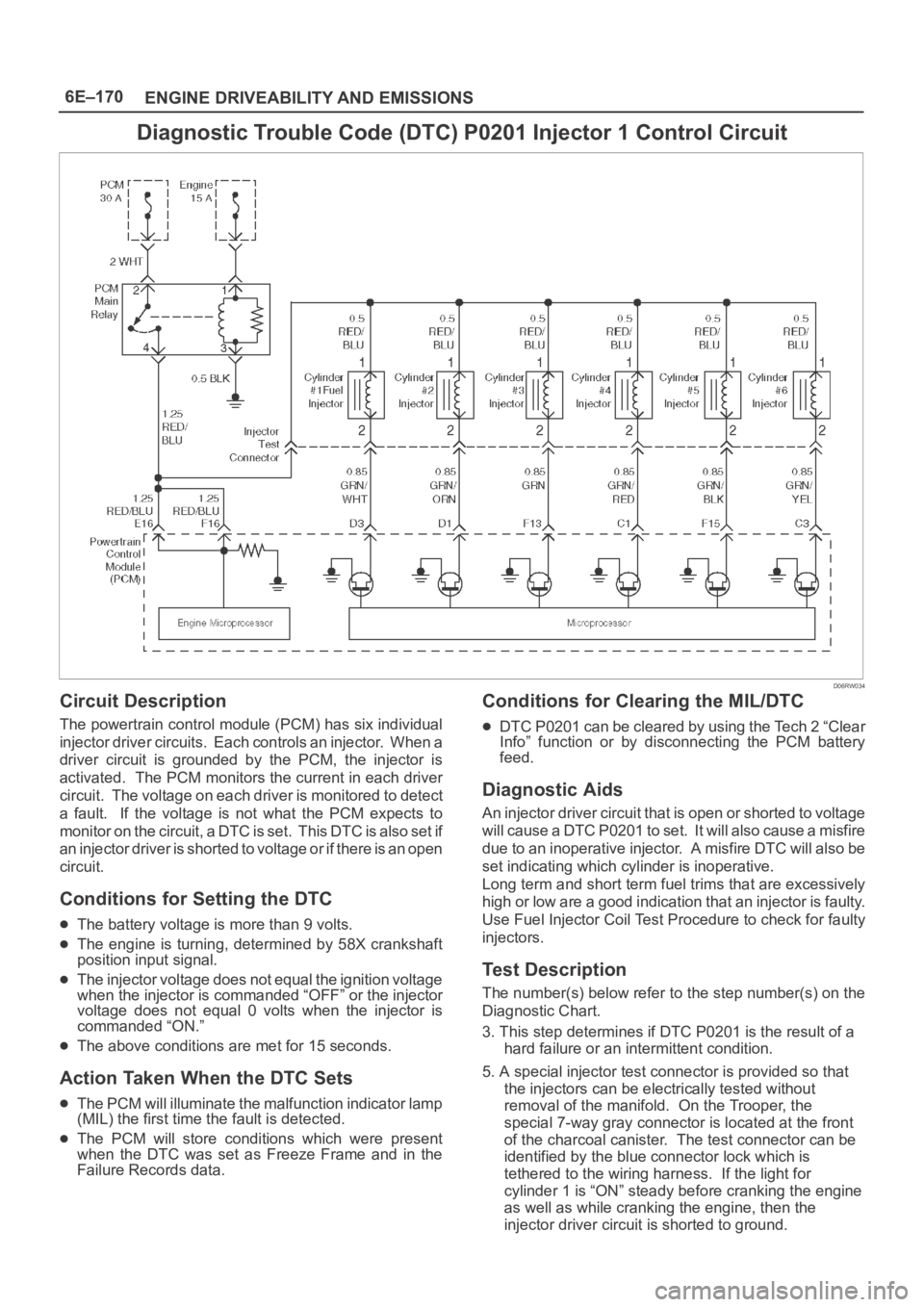
Diagnostic Trouble Code (DTC) P0201 Injector 1 Control Circuit
D06RW034
Circuit Description
The powertrain control module (PCM) has six individual
injector driver circuits. Each controls an injector. When a
driver circuit is grounded by the PCM, the injector is
activated. The PCM monitors the current in each driver
circuit. The voltage on each driver is monitored to detect
a fault. If the voltage is not what the PCM expects to
m o n i t o r o n t h e c i r c u i t , a D T C i s s e t . T h i s D T C i s a l s o s e t i f
an injector driver is shorted to voltage or if there is an open
circuit.
Conditions for Setting the DTC
The battery voltage is more than 9 volts.
The engine is turning, determined by 58X crankshaft
position input signal.
The injector voltage does not equal the ignition voltage
when the injector is commanded “OFF” or the injector
voltage does not equal 0 volts when the injector is
commanded “ON.”
The above conditions are met for 15 seconds.
Action Taken When the DTC Sets
The PCM will illuminate the malfunction indicator lamp
(MIL) the first time the fault is detected.
The PCM will store conditions which were present
when the DTC was set as Freeze Frame and in the
Failure Records data.
Conditions for Clearing the MIL/DTC
DTC P0201 can be cleared by using the Tech 2 “Clear
Info” function or by disconnecting the PCM battery
feed.
Diagnostic Aids
An injector driver circuit that is open or shorted to voltage
will cause a DTC P0201 to set. It will also cause a misfire
due to an inoperative injector. A misfire DTC will also be
set indicating which cylinder is inoperative.
Long term and short term fuel trims that are excessively
high or low are a good indication that an injector is faulty.
Use Fuel Injector Coil Test Procedure to check for faulty
injectors.
Test Description
The number(s) below refer to the step number(s) on the
Diagnostic Chart.
3. This step determines if DTC P0201 is the result of a
hard failure or an intermittent condition.
5. A special injector test connector is provided so that
the injectors can be electrically tested without
removal of the manifold. On the Trooper, the
special 7-way gray connector is located at the front
of the charcoal canister. The test connector can be
identified by the blue connector lock which is
tethered to the wiring harness. If the light for
cylinder 1 is “ON” steady before cranking the engine
as well as while cranking the engine, then the
injector driver circuit is shorted to ground.
Page 4830 of 6000
6E–173 ENGINE DRIVEABILITY AND EMISSIONS
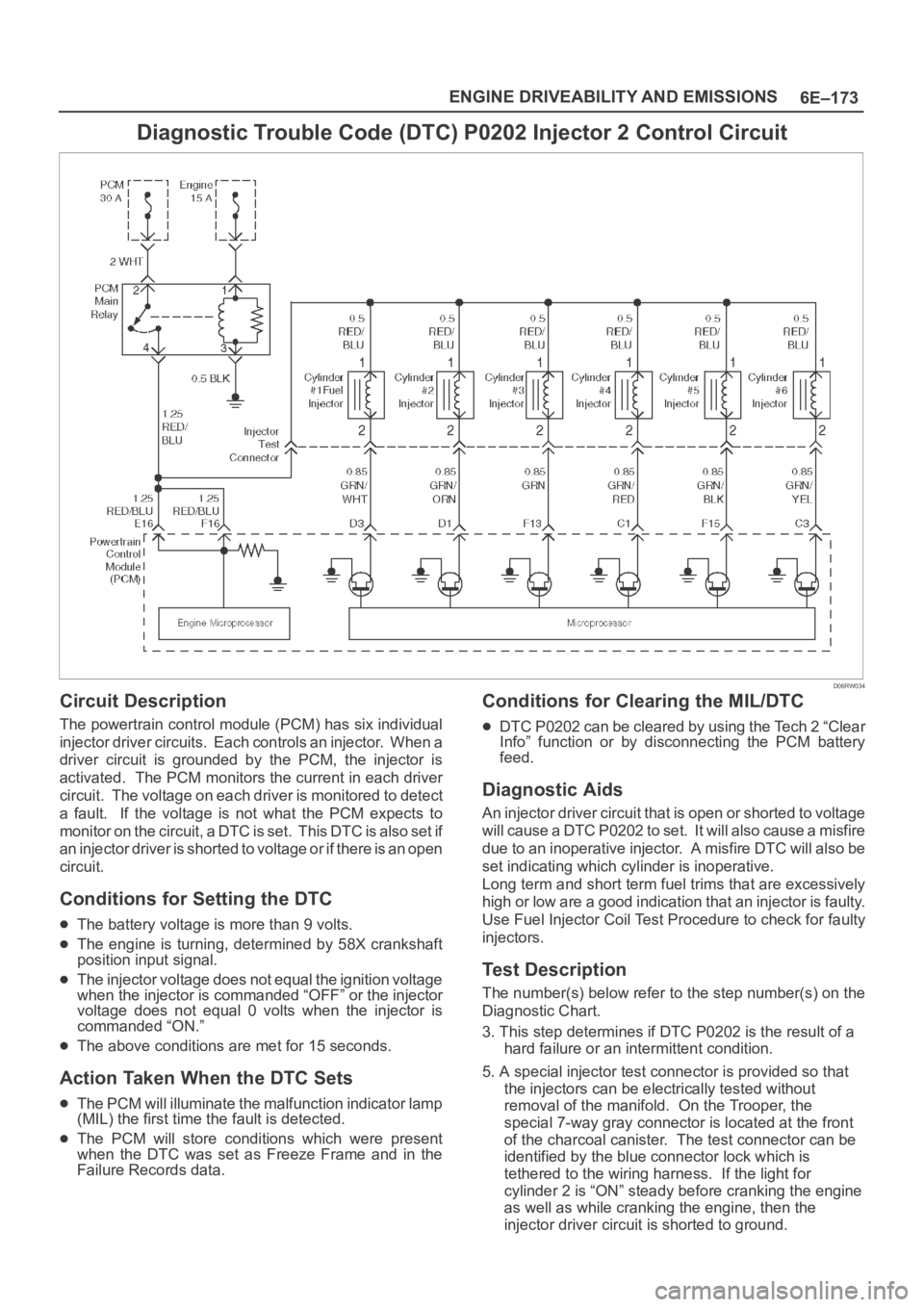
Diagnostic Trouble Code (DTC) P0202 Injector 2 Control Circuit
D06RW034
Circuit Description
The powertrain control module (PCM) has six individual
injector driver circuits. Each controls an injector. When a
driver circuit is grounded by the PCM, the injector is
activated. The PCM monitors the current in each driver
circuit. The voltage on each driver is monitored to detect
a fault. If the voltage is not what the PCM expects to
m o n i t o r o n t h e c i r c u i t , a D T C i s s e t . T h i s D T C i s a l s o s e t i f
an injector driver is shorted to voltage or if there is an open
circuit.
Conditions for Setting the DTC
The battery voltage is more than 9 volts.
The engine is turning, determined by 58X crankshaft
position input signal.
The injector voltage does not equal the ignition voltage
when the injector is commanded “OFF” or the injector
voltage does not equal 0 volts when the injector is
commanded “ON.”
The above conditions are met for 15 seconds.
Action Taken When the DTC Sets
The PCM will illuminate the malfunction indicator lamp
(MIL) the first time the fault is detected.
The PCM will store conditions which were present
when the DTC was set as Freeze Frame and in the
Failure Records data.
Conditions for Clearing the MIL/DTC
DTC P0202 can be cleared by using the Tech 2 “Clear
Info” function or by disconnecting the PCM battery
feed.
Diagnostic Aids
An injector driver circuit that is open or shorted to voltage
will cause a DTC P0202 to set. It will also cause a misfire
due to an inoperative injector. A misfire DTC will also be
set indicating which cylinder is inoperative.
Long term and short term fuel trims that are excessively
high or low are a good indication that an injector is faulty.
Use Fuel Injector Coil Test Procedure to check for faulty
injectors.
Test Description
The number(s) below refer to the step number(s) on the
Diagnostic Chart.
3. This step determines if DTC P0202 is the result of a
hard failure or an intermittent condition.
5. A special injector test connector is provided so that
the injectors can be electrically tested without
removal of the manifold. On the Trooper, the
special 7-way gray connector is located at the front
of the charcoal canister. The test connector can be
identified by the blue connector lock which is
tethered to the wiring harness. If the light for
cylinder 2 is “ON” steady before cranking the engine
as well as while cranking the engine, then the
injector driver circuit is shorted to ground.
Page 4833 of 6000
6E–176
ENGINE DRIVEABILITY AND EMISSIONS
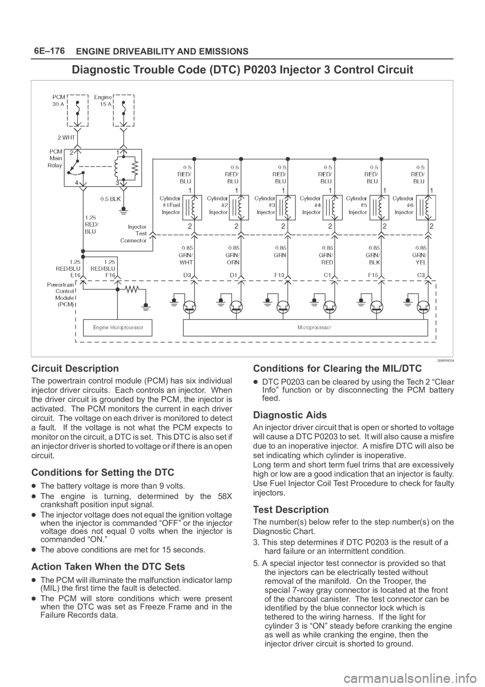
Diagnostic Trouble Code (DTC) P0203 Injector 3 Control Circuit
D06RW034
Circuit Description
The powertrain control module (PCM) has six individual
injector driver circuits. Each controls an injector. When
the driver circuit is grounded by the PCM, the injector is
activated. The PCM monitors the current in each driver
circuit. The voltage on each driver is monitored to detect
a fault. If the voltage is not what the PCM expects to
m o n i t o r o n t h e c i r c u i t , a D T C i s s e t . T h i s D T C i s a l s o s e t i f
an injector driver is shorted to voltage or if there is an open
circuit.
Conditions for Setting the DTC
The battery voltage is more than 9 volts.
The engine is turning, determined by the 58X
crankshaft position input signal.
The injector voltage does not equal the ignition voltage
when the injector is commanded “OFF” or the injector
voltage does not equal 0 volts when the injector is
commanded “ON.”
The above conditions are met for 15 seconds.
Action Taken When the DTC Sets
The PCM will illuminate the malfunction indicator lamp
(MIL) the first time the fault is detected.
The PCM will store conditions which were present
when the DTC was set as Freeze Frame and in the
Failure Records data.
Conditions for Clearing the MIL/DTC
DTC P0203 can be cleared by using the Tech 2 “Clear
Info” function or by disconnecting the PCM battery
feed.
Diagnostic Aids
An injector driver circuit that is open or shorted to voltage
will cause a DTC P0203 to set. It will also cause a misfire
due to an inoperative injector. A misfire DTC will also be
set indicating which cylinder is inoperative.
Long term and short term fuel trims that are excessively
high or low are a good indication that an injector is faulty.
Use Fuel Injector Coil Test Procedure to check for faulty
injectors.
Test Description
The number(s) below refer to the step number(s) on the
Diagnostic Chart.
3. This step determines if DTC P0203 is the result of a
hard failure or an intermittent condition.
5. A special injector test connector is provided so that
the injectors can be electrically tested without
removal of the manifold. On the Trooper, the
special 7-way gray connector is located at the front
of the charcoal canister. The test connector can be
identified by the blue connector lock which is
tethered to the wiring harness. If the light for
cylinder 3 is “ON” steady before cranking the engine
as well as while cranking the engine, then the
injector driver circuit is shorted to ground.
Page 4836 of 6000
6E–179 ENGINE DRIVEABILITY AND EMISSIONS
Diagnostic Trouble Code (DTC) P0204 Injector 4 Control Circuit
D06RW034
Circuit Description
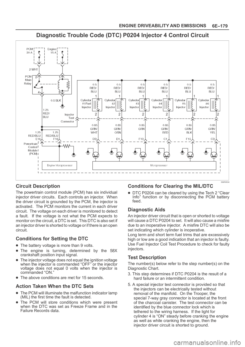
The powertrain control module (PCM) has six individual
injector driver circuits. Each controls an injector. When
the driver circuit is grounded by the PCM, the injector is
activated. The PCM monitors the current in each driver
circuit. The voltage on each driver is monitored to detect
a fault. If the voltage is not what the PCM expects to
m o n i t o r o n t h e c i r c u i t , a D T C i s s e t . T h i s D T C i s a l s o s e t i f
an injector driver is shorted to voltage or if there is an open
circuit.
Conditions for Setting the DTC
The battery voltage is more than 9 volts.
The engine is turning, determined by the 58X
crankshaft position input signal.
The injector voltage does not equal the ignition voltage
when the injector is commanded “OFF” or the injector
voltage does not equal 0 volts when the injector is
commanded “ON.”
The above conditions are met for 15 seconds.
Action Taken When the DTC Sets
The PCM will illuminate the malfunction indicator lamp
(MIL) the first time the fault is detected.
The PCM will store conditions which were present
when the DTC was set as Freeze Frame and in the
Failure Records data.
Conditions for Clearing the MIL/DTC
DTC P0204 can be cleared by using the Tech 2 “Clear
Info” function or by disconnecting the PCM battery
feed.
Diagnostic Aids
An injector driver circuit that is open or shorted to voltage
will cause a DTC P0204 to set. It will also cause a misfire
due to an inoperative injector. A misfire DTC will also be
set indicating which cylinder is inoperative.
Long term and short term fuel trims that are excessively
high or low are a good indication that an injector is faulty.
Use Fuel Injector Coil Test Procedure to check for faulty
injectors.
Test Description
The number(s) below refer to the step number(s) on the
Diagnostic Chart.
3. This step determines if DTC P0204 is the result of a
hard failure or an intermittent condition.
5. A special injector test connector is provided so that
the injectors can be electrically tested without
removal of the manifold. On the Trooper, the
special 7-way gray connector is located at the front
of the charcoal canister. The test connector can be
identified by the blue connector lock which is
tethered to the wiring harness. If the light for
cylinder 4 is “ON” steady before cranking the engine
as well as while cranking the engine, then the
injector driver circuit is shorted to ground.
Page 4839 of 6000
6E–182
ENGINE DRIVEABILITY AND EMISSIONS
Diagnostic Trouble Code (DTC) P0205 Injector 5 Control Circuit
D06RW034
Circuit Description
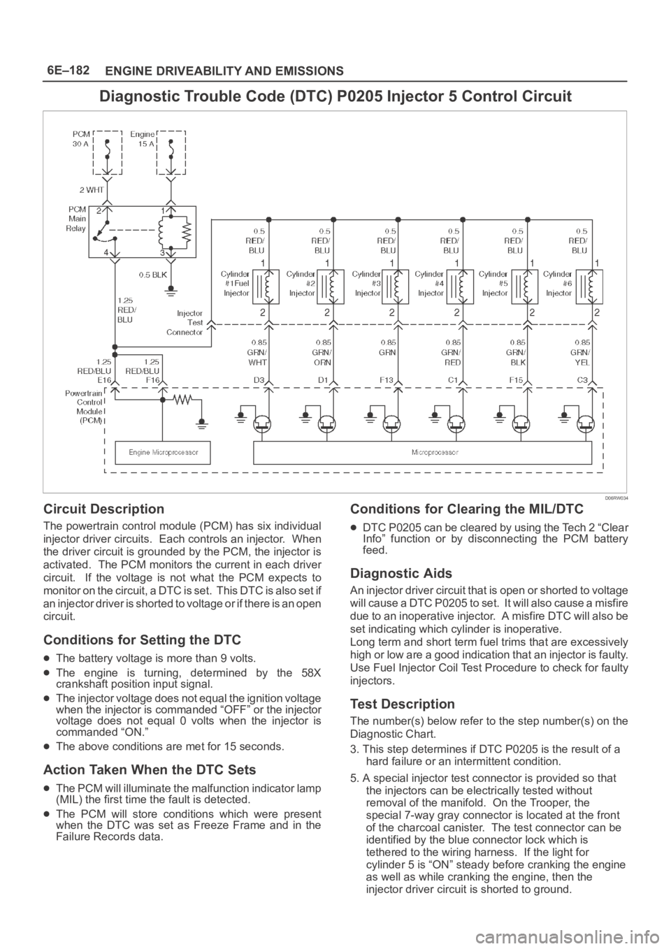
The powertrain control module (PCM) has six individual
injector driver circuits. Each controls an injector. When
the driver circuit is grounded by the PCM, the injector is
activated. The PCM monitors the current in each driver
circuit. If the voltage is not what the PCM expects to
m o n i t o r o n t h e c i r c u i t , a D T C i s s e t . T h i s D T C i s a l s o s e t i f
an injector driver is shorted to voltage or if there is an open
circuit.
Conditions for Setting the DTC
The battery voltage is more than 9 volts.
The engine is turning, determined by the 58X
crankshaft position input signal.
The injector voltage does not equal the ignition voltage
when the injector is commanded “OFF” or the injector
voltage does not equal 0 volts when the injector is
commanded “ON.”
The above conditions are met for 15 seconds.
Action Taken When the DTC Sets
The PCM will illuminate the malfunction indicator lamp
(MIL) the first time the fault is detected.
The PCM will store conditions which were present
when the DTC was set as Freeze Frame and in the
Failure Records data.
Conditions for Clearing the MIL/DTC
DTC P0205 can be cleared by using the Tech 2 “Clear
Info” function or by disconnecting the PCM battery
feed.
Diagnostic Aids
An injector driver circuit that is open or shorted to voltage
will cause a DTC P0205 to set. It will also cause a misfire
due to an inoperative injector. A misfire DTC will also be
set indicating which cylinder is inoperative.
Long term and short term fuel trims that are excessively
high or low are a good indication that an injector is faulty.
Use Fuel Injector Coil Test Procedure to check for faulty
injectors.
Test Description
The number(s) below refer to the step number(s) on the
Diagnostic Chart.
3. This step determines if DTC P0205 is the result of a
hard failure or an intermittent condition.
5. A special injector test connector is provided so that
the injectors can be electrically tested without
removal of the manifold. On the Trooper, the
special 7-way gray connector is located at the front
of the charcoal canister. The test connector can be
identified by the blue connector lock which is
tethered to the wiring harness. If the light for
cylinder 5 is “ON” steady before cranking the engine
as well as while cranking the engine, then the
injector driver circuit is shorted to ground.
Page 4842 of 6000
6E–185 ENGINE DRIVEABILITY AND EMISSIONS
Diagnostic Trouble Code (DTC) P0206 Injector 6 Control Circuit
D06RW034
Circuit Description
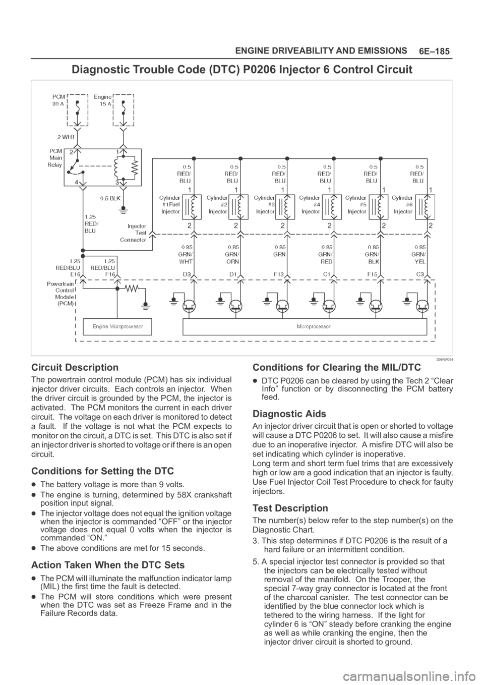
The powertrain control module (PCM) has six individual
injector driver circuits. Each controls an injector. When
the driver circuit is grounded by the PCM, the injector is
activated. The PCM monitors the current in each driver
circuit. The voltage on each driver is monitored to detect
a fault. If the voltage is not what the PCM expects to
m o n i t o r o n t h e c i r c u i t , a D T C i s s e t . T h i s D T C i s a l s o s e t i f
an injector driver is shorted to voltage or if there is an open
circuit.
Conditions for Setting the DTC
The battery voltage is more than 9 volts.
The engine is turning, determined by 58X crankshaft
position input signal.
The injector voltage does not equal the ignition voltage
when the injector is commanded “OFF” or the injector
voltage does not equal 0 volts when the injector is
commanded “ON.”
The above conditions are met for 15 seconds.
Action Taken When the DTC Sets
The PCM will illuminate the malfunction indicator lamp
(MIL) the first time the fault is detected.
The PCM will store conditions which were present
when the DTC was set as Freeze Frame and in the
Failure Records data.
Conditions for Clearing the MIL/DTC
DTC P0206 can be cleared by using the Tech 2 “Clear
Info” function or by disconnecting the PCM battery
feed.
Diagnostic Aids
An injector driver circuit that is open or shorted to voltage
will cause a DTC P0206 to set. It will also cause a misfire
due to an inoperative injector. A misfire DTC will also be
set indicating which cylinder is inoperative.
Long term and short term fuel trims that are excessively
high or low are a good indication that an injector is faulty.
Use Fuel Injector Coil Test Procedure to check for faulty
injectors.
Test Description
The number(s) below refer to the step number(s) on the
Diagnostic Chart.
3. This step determines if DTC P0206 is the result of a
hard failure or an intermittent condition.
5. A special injector test connector is provided so that
the injectors can be electrically tested without
removal of the manifold. On the Trooper, the
special 7-way gray connector is located at the front
of the charcoal canister. The test connector can be
identified by the blue connector lock which is
tethered to the wiring harness. If the light for
cylinder 6 is “ON” steady before cranking the engine
as well as while cranking the engine, then the
injector driver circuit is shorted to ground.
Page 4845 of 6000
6E–188
ENGINE DRIVEABILITY AND EMISSIONS
Diagnostic Trouble Code (DTC) P0325 KS Module Circuit
D06RW035
Circuit Description
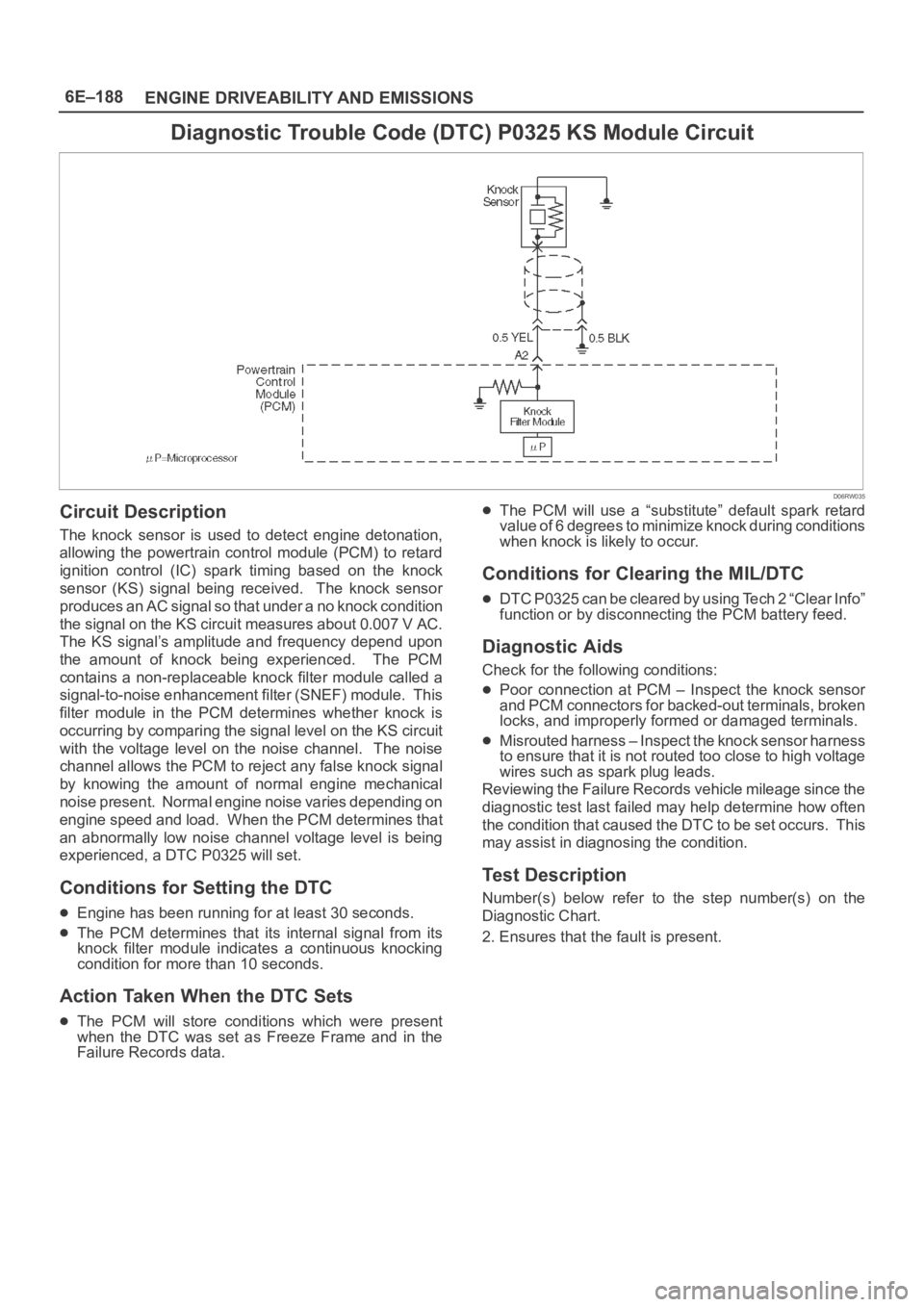
The knock sensor is used to detect engine detonation,
allowing the powertrain control module (PCM) to retard
ignition control (IC) spark timing based on the knock
sensor (KS) signal being received. The knock sensor
produces an AC signal so that under a no knock condition
the signal on the KS circuit measures about 0.007 V AC.
The KS signal’s amplitude and frequency depend upon
the amount of knock being experienced. The PCM
contains a non-replaceable knock filter module called a
signal-to-noise enhancement filter (SNEF) module. This
filter module in the PCM determines whether knock is
occurring by comparing the signal level on the KS circuit
with the voltage level on the noise channel. The noise
channel allows the PCM to reject any false knock signal
by knowing the amount of normal engine mechanical
noise present. Normal engine noise varies depending on
engine speed and load. When the PCM determines that
an abnormally low noise channel voltage level is being
experienced, a DTC P0325 will set.
Conditions for Setting the DTC
Engine has been running for at least 30 seconds.
The PCM determines that its internal signal from its
knock filter module indicates a continuous knocking
condition for more than 10 seconds.
Action Taken When the DTC Sets
The PCM will store conditions which were present
when the DTC was set as Freeze Frame and in the
Failure Records data.
The PCM will use a “substitute” default spark retard
value of 6 degrees to minimize knock during conditions
when knock is likely to occur.
Conditions for Clearing the MIL/DTC
DTC P0325 can be cleared by using Tech 2 “Clear Info”
function or by disconnecting the PCM battery feed.
Diagnostic Aids
Check for the following conditions:
Poor connection at PCM – Inspect the knock sensor
and PCM connectors for backed-out terminals, broken
locks, and improperly formed or damaged terminals.
Misrouted harness – Inspect the knock sensor harness
to ensure that it is not routed too close to high voltage
wires such as spark plug leads.
Reviewing the Failure Records vehicle mileage since the
diagnostic test last failed may help determine how often
the condition that caused the DTC to be set occurs. This
may assist in diagnosing the condition.
Test Description
Number(s) below refer to the step number(s) on the
Diagnostic Chart.
2. Ensures that the fault is present.