1998 OPEL FRONTERA air condition
[x] Cancel search: air conditionPage 5549 of 6000
6E–120
4JX1–TC ENGINE DRIVEABILITY AND EMISSIONS
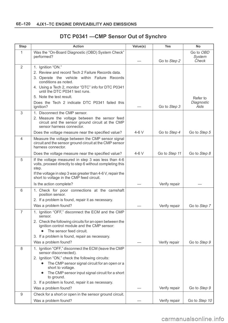
DTC P0341 —CMP Sensor Out of Synchro
StepActionVa l u e ( s )Ye sNo
1Was the “On-Board Diagnostic (OBD) System Check”
performed?
—Go to Step 2
Go to OBD
System
Check
21. Ignition “ON.”
2. Review and record Tech 2 Failure Records data.
3. Operate the vehicle within Failure Records
conditions as noted.
4. Using a Tech 2, monitor “DTC” info for DTC P0341
until the DTC P0341 test runs.
5. Note the test result.
Does the Tech 2 indicate DTC P0341 failed this
ignition?
—Go to Step 3
Refer to
Diagnostic
Aids
31. Disconnect the CMP sensor.
2. Measure the voltage between the sensor feed
circuit and the sensor ground circuit at the CMP
sensor harness connector.
Does the voltage measure near the specified value?
4-6 VGo to Step 4Go to Step 5
4Measure the voltage between the CMP sensor signal
circuit and the sensor ground circuit at the CMP sensor
harness connector.
Does the voltage measure near the specified value?
4-6 VGo to Step 11Go to Step 8
5If the voltage measured in step 3 was less than 4-6
volts, proceed directly to step 6 without completing this
step.
If the voltage in step 3 was greater than 4-6 V, repair the
short to voltage in the CMP feed circuit.
Is the action complete?
—Verify repair—
61. Check for poor connections at the camshaft
position sensor.
2. If a problem is found, repair it as necessary.
Was a problem found?
—Verify repairGo to Step 7
71. Ignition “OFF,” disconnect the ECM and the CMP
sensor.
2. Check the following circuits for an open between the
ignition control module and the CMP sensor:
The sensor feed circuit.
3. If a problem is found, repair as necessary.
Was a problem found?
—Verify repair Go to Step 9
81. Ignition “OFF,” disconnect the ECM (leave the CMP
sensor disconnected).
2. Ignition “ON,” check the following circuits:
The CMP sensor signal circuit for an open or a
short to voltage.
The CMP sensor input signal circuit for a short
to ground.
3. If a problem is found, repair it as necessary.
Was a problem found?
—Verify repairGo to Step 9
9Check for a short or open in the sensor ground circuit.
Was a problem found?
—Verify repairGo to Step 10
Page 5552 of 6000
6E–123 4JX1–TC ENGINE DRIVEABILITY AND EMISSIONS
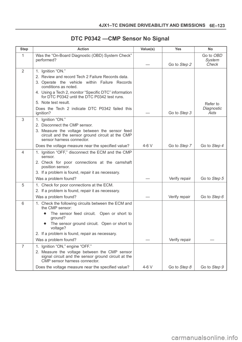
DTC P0342 —CMP Sensor No Signal
StepActionVa l u e ( s )Ye sNo
1Was the “On-Board Diagnostic (OBD) System Check”
performed?
—Go to Step 2
Go to OBD
System
Check
21. Ignition “ON.”
2. Review and record Tech 2 Failure Records data.
3. Operate the vehicle within Failure Records
conditions as noted.
4. Using a Tech 2, monitor “Specific DTC” information
for DTC P0342 until the DTC P0342 test runs.
5. Note test result.
Does the Tech 2 indicate DTC P0342 failed this
ignition?
—Go to Step 3
Refer to
Diagnostic
Aids
31. Ignition “ON.”
2. Disconnect the CMP sensor.
3. Measure the voltage between the sensor feed
circuit and the sensor ground circuit at the CMP
sensor harness connector.
Does the voltage measure near the specified value?
4-6 VGo to Step 7Go to Step 4
41. Ignition “OFF,” disconnect the ECM and the CMP
sensor.
2. Check for poor connections at the camshaft
position sensor.
3. If a problem is found, repair it as necessary.
Was a problem found?
—Verify repairGo to Step 5
51. Check for poor connections at the ECM.
2. If a problem is found, repair it as necessary.
Was a problem found?
—Verify repair Go to Step 6
61. Check the following circuits between the ECM and
the CMP sensor:
The sensor feed circuit. Open or short to
ground?
The sensor ground circuit. Open or short to
voltage?
2. If a problem is found, repair as necessary.
Was a problem found?
—Verify repair—
71. Ignition “ON,” engine “OFF.”
2. Measure the voltage between the CMP sensor
signal circuit and the sensor ground circuit at the
CMP sensor harness connector.
Does the voltage measure near the specified value?
4-6 VGo to Step 8Go to Step 9
Page 5560 of 6000
6E–131 4JX1–TC ENGINE DRIVEABILITY AND EMISSIONS
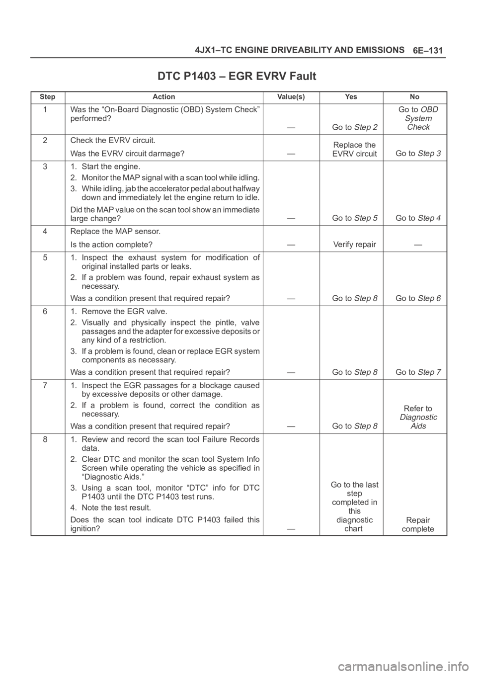
DTC P1403 – EGR EVRV Fault
StepActionVa l u e ( s )Ye sNo
1Was the “On-Board Diagnostic (OBD) System Check”
performed?
—Go to Step 2
Go to OBD
System
Check
2Check the EVRV circuit.
Was the EVRV circuit darmage?
—
Replace the
EVRV circuit
Go to Step 3
31. Start the engine.
2. Monitor the MAP signal with a scan tool while idling.
3. While idling, jab the accelerator pedal about halfway
down and immediately let the engine return to idle.
Did the MAP value on the scan tool show an immediate
large change?
—Go to Step 5Go to Step 4
4Replace the MAP sensor.
Is the action complete?
—Verify repair—
51. Inspect the exhaust system for modification of
original installed parts or leaks.
2. If a problem was found, repair exhaust system as
necessary.
Was a condition present that required repair?
—Go to Step 8Go to Step 6
61. Remove the EGR valve.
2. Visually and physically inspect the pintle, valve
passages and the adapter for excessive deposits or
any kind of a restriction.
3. If a problem is found, clean or replace EGR system
components as necessary.
Was a condition present that required repair?
—Go to Step 8Go to Step 7
71. Inspect the EGR passages for a blockage caused
by excessive deposits or other damage.
2. If a problem is found, correct the condition as
necessary.
Was a condition present that required repair?
—Go to Step 8
Refer to
Diagnostic
Aids
81. Review and record the scan tool Failure Records
data.
2. Clear DTC and monitor the scan tool System Info
Screen while operating the vehicle as specified in
“Diagnostic Aids.”
3. Using a scan tool, monitor “DTC” info for DTC
P1403 until the DTC P1403 test runs.
4. Note the test result.
Does the scan tool indicate DTC P1403 failed this
ignition?
—
Go to the last
step
completed in
this
diagnostic
chart
Repair
complete
Page 5570 of 6000
6E–141 4JX1–TC ENGINE DRIVEABILITY AND EMISSIONS
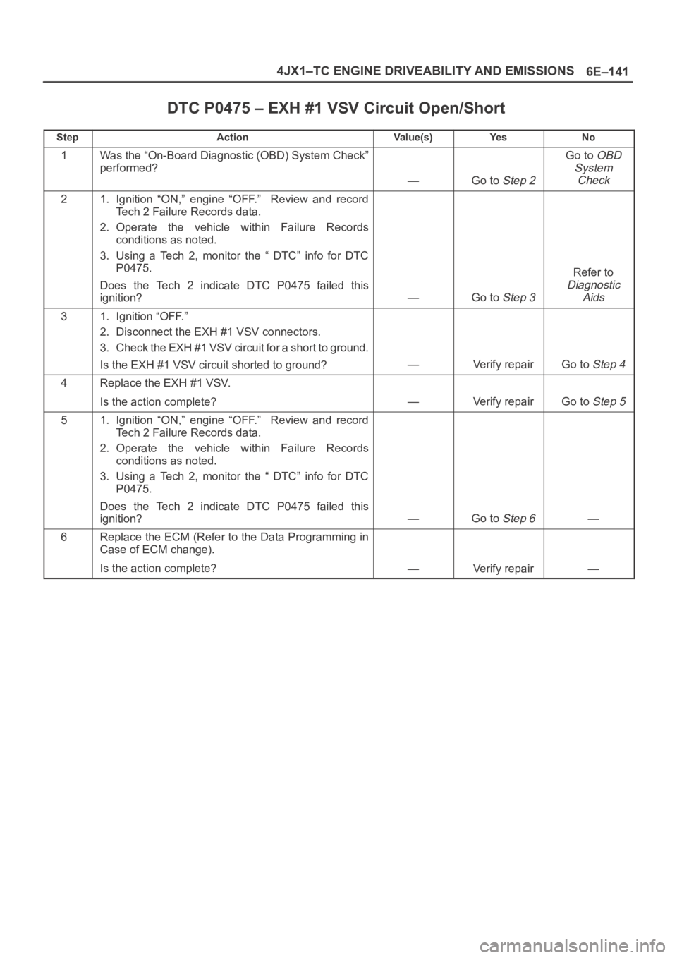
DTC P0475 – EXH #1 VSV Circuit Open/Short
StepActionVa l u e ( s )Ye sNo
1Was the “On-Board Diagnostic (OBD) System Check”
performed?
—Go to Step 2
Go to OBD
System
Check
21. Ignition “ON,” engine “OFF.” Review and record
Tech 2 Failure Records data.
2. Operate the vehicle within Failure Records
conditions as noted.
3. Using a Tech 2, monitor the “ DTC” info for DTC
P0475.
Does the Tech 2 indicate DTC P0475 failed this
ignition?
—Go to Step 3
Refer to
Diagnostic
Aids
31. Ignition “OFF.”
2. Disconnect the EXH #1 VSV connectors.
3. Check the EXH #1 VSV circuit for a short to ground.
Is the EXH #1 VSV circuit shorted to ground?
—Verify repairGo to Step 4
4Replace the EXH #1 VSV.
Is the action complete?
—Verify repairGo to Step 5
51. Ignition “ON,” engine “OFF.” Review and record
Tech 2 Failure Records data.
2. Operate the vehicle within Failure Records
conditions as noted.
3. Using a Tech 2, monitor the “ DTC” info for DTC
P0475.
Does the Tech 2 indicate DTC P0475 failed this
ignition?
—Go to Step 6—
6Replace the ECM (Refer to the Data Programming in
Case of ECM change).
Is the action complete?
—Verify repair—
Page 5572 of 6000
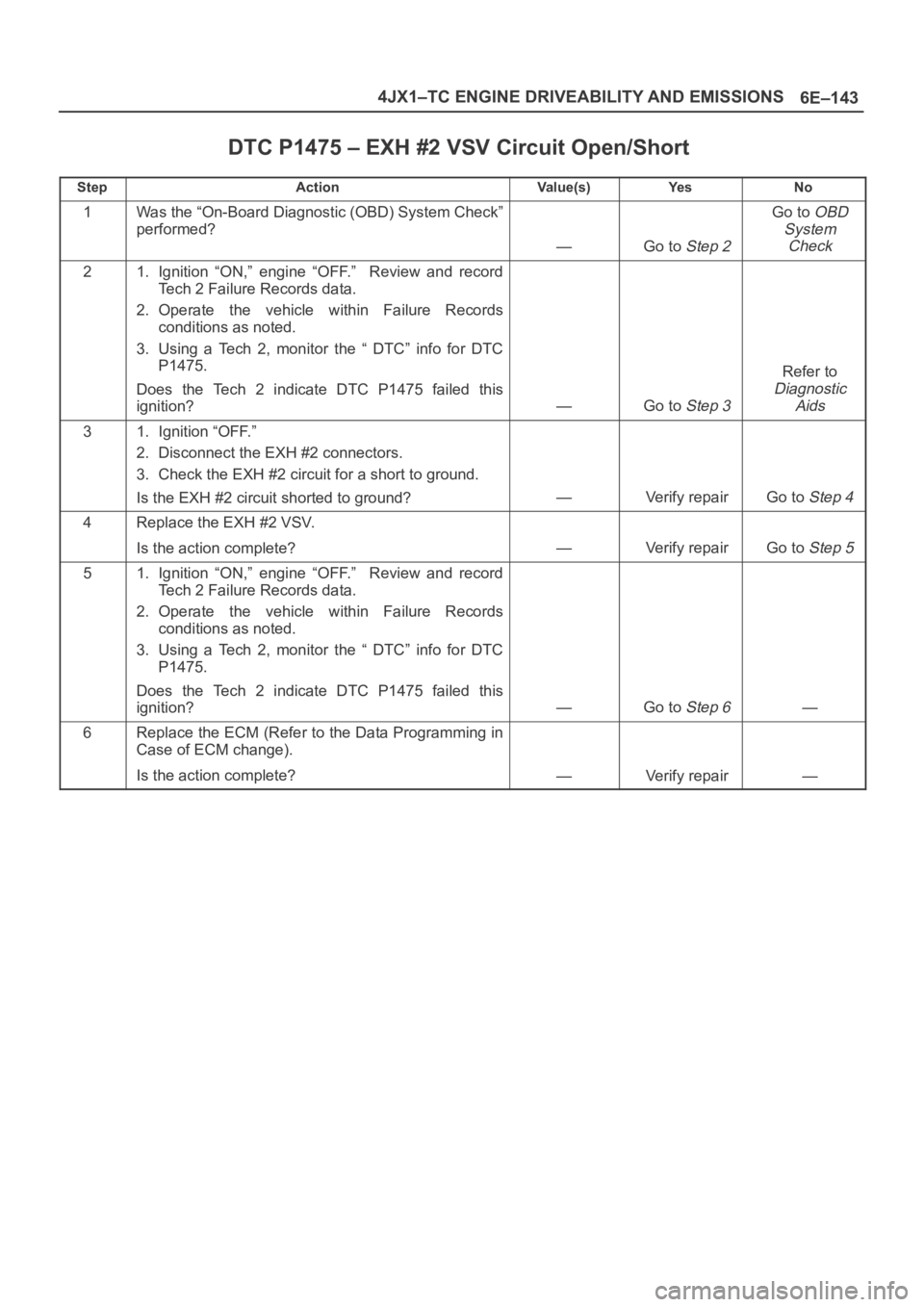
6E–143 4JX1–TC ENGINE DRIVEABILITY AND EMISSIONS
DTC P1475 – EXH #2 VSV Circuit Open/Short
StepActionVa l u e ( s )Ye sNo
1Was the “On-Board Diagnostic (OBD) System Check”
performed?
—Go to Step 2
Go to OBD
System
Check
21. Ignition “ON,” engine “OFF.” Review and record
Tech 2 Failure Records data.
2. Operate the vehicle within Failure Records
conditions as noted.
3. Using a Tech 2, monitor the “ DTC” info for DTC
P1475.
Does the Tech 2 indicate DTC P1475 failed this
ignition?
—Go to Step 3
Refer to
Diagnostic
Aids
31. Ignition “OFF.”
2. Disconnect the EXH #2 connectors.
3. Check the EXH #2 circuit for a short to ground.
Is the EXH #2 circuit shorted to ground?
—Verify repairGo to Step 4
4Replace the EXH #2 VSV.
Is the action complete?
—Verify repairGo to Step 5
51. Ignition “ON,” engine “OFF.” Review and record
Tech 2 Failure Records data.
2. Operate the vehicle within Failure Records
conditions as noted.
3. Using a Tech 2, monitor the “ DTC” info for DTC
P1475.
Does the Tech 2 indicate DTC P1475 failed this
ignition?
—Go to Step 6—
6Replace the ECM (Refer to the Data Programming in
Case of ECM change).
Is the action complete?
—Verify repair—
Page 5574 of 6000
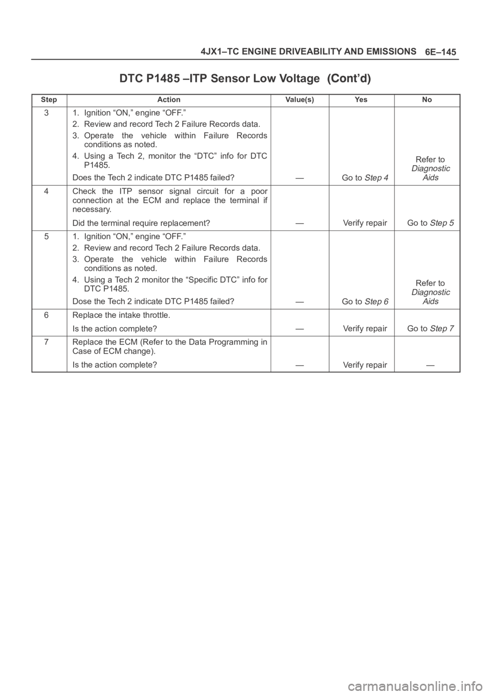
6E–145 4JX1–TC ENGINE DRIVEABILITY AND EMISSIONS
DTC P1485 –ITP Sensor Low Voltage
StepNo Ye s Va l u e ( s ) Action
31. Ignition “ON,” engine “OFF.”
2. Review and record Tech 2 Failure Records data.
3. Operate the vehicle within Failure Records
conditions as noted.
4. Using a Tech 2, monitor the “DTC” info for DTC
P1485.
Does the Tech 2 indicate DTC P1485 failed?
—Go to Step 4
Refer to
Diagnostic
Aids
4Check the ITP sensor signal circuit for a poor
connection at the ECM and replace the terminal if
necessary.
Did the terminal require replacement?
—Verify repairGo to Step 5
51. Ignition “ON,” engine “OFF.”
2. Review and record Tech 2 Failure Records data.
3. Operate the vehicle within Failure Records
conditions as noted.
4. Using a Tech 2 monitor the “Specific DTC” info for
DTC P1485.
Dose the Tech 2 indicate DTC P1485 failed?
—Go to Step 6
Refer to
Diagnostic
Aids
6Replace the intake throttle.
Is the action complete?
—Verify repairGo to Step 7
7Replace the ECM (Refer to the Data Programming in
Case of ECM change).
Is the action complete?
—Verify repair—
Page 5576 of 6000
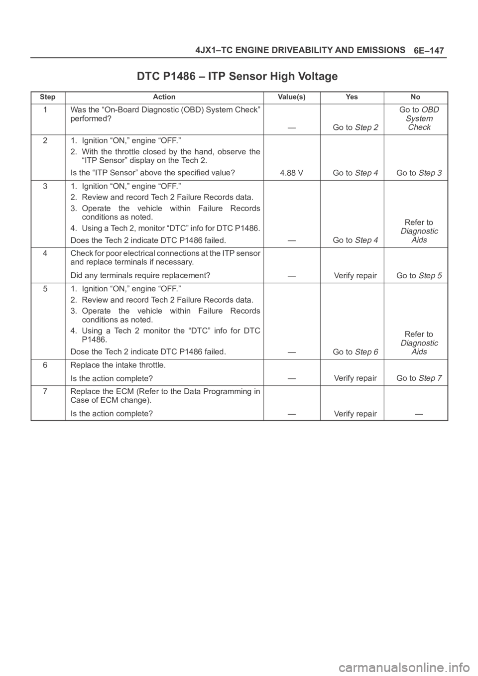
6E–147 4JX1–TC ENGINE DRIVEABILITY AND EMISSIONS
DTC P1486 – ITP Sensor High Voltage
StepActionVa l u e ( s )Ye sNo
1Was the “On-Board Diagnostic (OBD) System Check”
performed?
—Go to Step 2
Go to OBD
System
Check
21. Ignition “ON,” engine “OFF.”
2. With the throttle closed by the hand, observe the
“ITP Sensor” display on the Tech 2.
Is the “ITP Sensor” above the specified value?
4.88 VGo to Step 4Go to Step 3
31. Ignition “ON,” engine “OFF.”
2. Review and record Tech 2 Failure Records data.
3. Operate the vehicle within Failure Records
conditions as noted.
4. Using a Tech 2, monitor “DTC” info for DTC P1486.
Does the Tech 2 indicate DTC P1486 failed.
—Go to Step 4
Refer to
Diagnostic
Aids
4Check for poor electrical connections at the ITP sensor
and replace terminals if necessary.
Did any terminals require replacement?
—Verify repairGo to Step 5
51. Ignition “ON,” engine “OFF.”
2. Review and record Tech 2 Failure Records data.
3. Operate the vehicle within Failure Records
conditions as noted.
4. Using a Tech 2 monitor the “DTC” info for DTC
P1486.
Dose the Tech 2 indicate DTC P1486 failed.
—Go to Step 6
Refer to
Diagnostic
Aids
6Replace the intake throttle.
Is the action complete?
—Verify repairGo to Step 7
7Replace the ECM (Refer to the Data Programming in
Case of ECM change).
Is the action complete?
—Verify repair—
Page 5578 of 6000
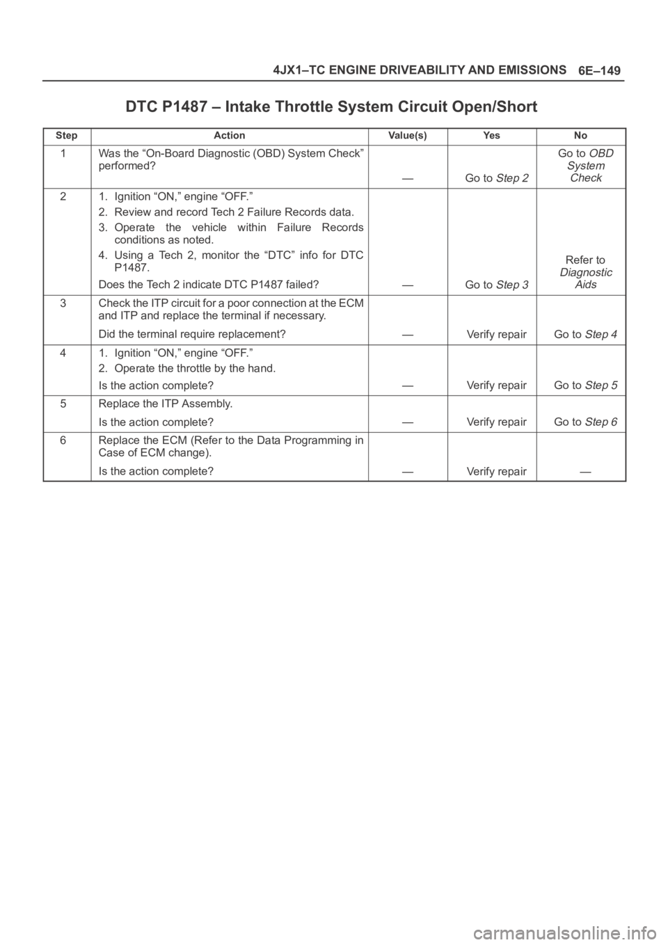
6E–149 4JX1–TC ENGINE DRIVEABILITY AND EMISSIONS
DTC P1487 – Intake Throttle System Circuit Open/Short
StepActionVa l u e ( s )Ye sNo
1Was the “On-Board Diagnostic (OBD) System Check”
performed?
—Go to Step 2
Go to OBD
System
Check
21. Ignition “ON,” engine “OFF.”
2. Review and record Tech 2 Failure Records data.
3. Operate the vehicle within Failure Records
conditions as noted.
4. Using a Tech 2, monitor the “DTC” info for DTC
P1487.
Does the Tech 2 indicate DTC P1487 failed?
—Go to Step 3
Refer to
Diagnostic
Aids
3Check the ITP circuit for a poor connection at the ECM
and ITP and replace the terminal if necessary.
Did the terminal require replacement?
—Verify repairGo to Step 4
41. Ignition “ON,” engine “OFF.”
2. Operate the throttle by the hand.
Is the action complete?
—Verify repairGo to Step 5
5Replace the ITP Assembly.
Is the action complete?
—Verify repairGo to Step 6
6Replace the ECM (Refer to the Data Programming in
Case of ECM change).
Is the action complete?
—Verify repair—