Page 4632 of 6000

6D3–1 STARTING AND CHARGING SYSTEM
ENGINE
STARTING AND CHARGING SYSTEM
CONTENTS
Service Precaution 6D3–1. . . . . . . . . . . . . . . . . . . . . .
Starting System 6D3–2. . . . . . . . . . . . . . . . . . . . . . . . .
General Description 6D3–2. . . . . . . . . . . . . . . . . . . . .
Diagnosis 6D3–4. . . . . . . . . . . . . . . . . . . . . . . . . . . . . .
Starter 6D3–5. . . . . . . . . . . . . . . . . . . . . . . . . . . . . . . . .
Removal 6D3–5. . . . . . . . . . . . . . . . . . . . . . . . . . . . .
Installation 6D3–5. . . . . . . . . . . . . . . . . . . . . . . . . . . .
Disassembled View 6D3–6. . . . . . . . . . . . . . . . . . . .
Disassembly 6D3–7. . . . . . . . . . . . . . . . . . . . . . . . . .
Inspection and Repair 6D3–9. . . . . . . . . . . . . . . . . .
Reassembly 6D3–13. . . . . . . . . . . . . . . . . . . . . . . . . .
Main Data and Specifications 6D3–15. . . . . . . . . . .
Charging System 6D3–18. . . . . . . . . . . . . . . . . . . . . . . . General Description 6D3–18. . . . . . . . . . . . . . . . . . . . .
General On–Vehicle Inspection 6D3–18. . . . . . . . . . .
Generator 6D3–19. . . . . . . . . . . . . . . . . . . . . . . . . . . . . .
Removal 6D3–19. . . . . . . . . . . . . . . . . . . . . . . . . . . . .
Inspection 6D3–19. . . . . . . . . . . . . . . . . . . . . . . . . . . .
Installation 6D3–19. . . . . . . . . . . . . . . . . . . . . . . . . . . .
Disassembled View 6D3–20. . . . . . . . . . . . . . . . . . . .
Disassembly 6D3–21. . . . . . . . . . . . . . . . . . . . . . . . . .
Inspection and Repair 6D3–23. . . . . . . . . . . . . . . . . .
Reassembly 6D3–24. . . . . . . . . . . . . . . . . . . . . . . . . .
Bench Test 6D3–25. . . . . . . . . . . . . . . . . . . . . . . . . . .
Main Data and Specifications 6D3–26. . . . . . . . . . .
Service Precaution
WARNING: IF SO EQUIPPED WITH A
SUPPLEMENTAL RESTRAINT SYSTEM (SRS),
REFER TO THE SRS COMPONENT AND WIRING
LOCATION VIEW IN ORDER TO DETERMINE
WHETHER YOU ARE PERFORMING SERVICE ON OR
NEAR THE SRS COMPONENTS OR THE SRS
WIRING. WHEN YOU ARE PERFORMING SERVICE
ON OR NEAR THE SRS COMPONENTS OR THE SRS
WIRING, REFER TO THE SRS SERVICE
INFORMATION. FAILURE TO FOLLOW WARNINGS
COULD RESULT IN POSSIBLE AIR BAG
DEPLOYMENT, PERSONAL INJURY, OR
OTHERWISE UNNEEDED SRS SYSTEM REPAIRS.
CAUTION: Always use the correct fastener in the
proper location. When you replace a fastener, use
ONLY the exact part number for that application.
ISUZU will call out those fasteners that require a
replacement after removal. ISUZU will also call out
the fasteners that require thread lockers or thread
sealant. UNLESS OTHERWISE SPECIFIED, do not
use supplemental coatings (Paints, greases, or other
corrosion inhibitors) on threaded fasteners or
fastener joint interfaces. Generally, such coatings
adversely affect the fastener torque and the joint
clamping force, and may damage the fastener. When
you install fasteners, use the correct tightening
sequence and specifications. Following these
instructions can help you avoid damage to parts and
systems.
Page 4636 of 6000
6D3–5 STARTING AND CHARGING SYSTEM
Starter
Removal
1. Battery ground cable.
2. Remove exhaust front left pipe(1).
150RW062
3. Remove heat protector(3).
4. Disconnect starter wiring connector from terminals
“B” and “S”(4).
5. Remove starter assembly mounting bolts on inside
and outside(5).
6. Remove starter assembly toward the bottom of
engine(6).
065RW027
Installation
1. Install starter assembly(6).2. Install mounting bolts and tighten bolts to specified
torque(5).
Torque: 40 Nꞏm (4.1 Kgꞏm/30 lb ft)
3. Reconnect the connectors to terminals “B” and “S”
and tighten Terminals “B” to specified torque.
Torque: 9 Nꞏm (0.9 Kgꞏm/80 lb in)
4. Install heat protector(3).
065RW027
5. Install exhaust front left pipe and tighten bolts and
nuts to specified torque(2).
Stud Nuts
Torque: 67 Nꞏm (6.8 Kgꞏm/49 lb ft)
Nuts
Torque: 43 Nꞏm (4.4 Kgꞏm/32 lb ft)
150RW062
6. Reconnect the battery ground cable.
Page 4644 of 6000

6D3–13 STARTING AND CHARGING SYSTEM
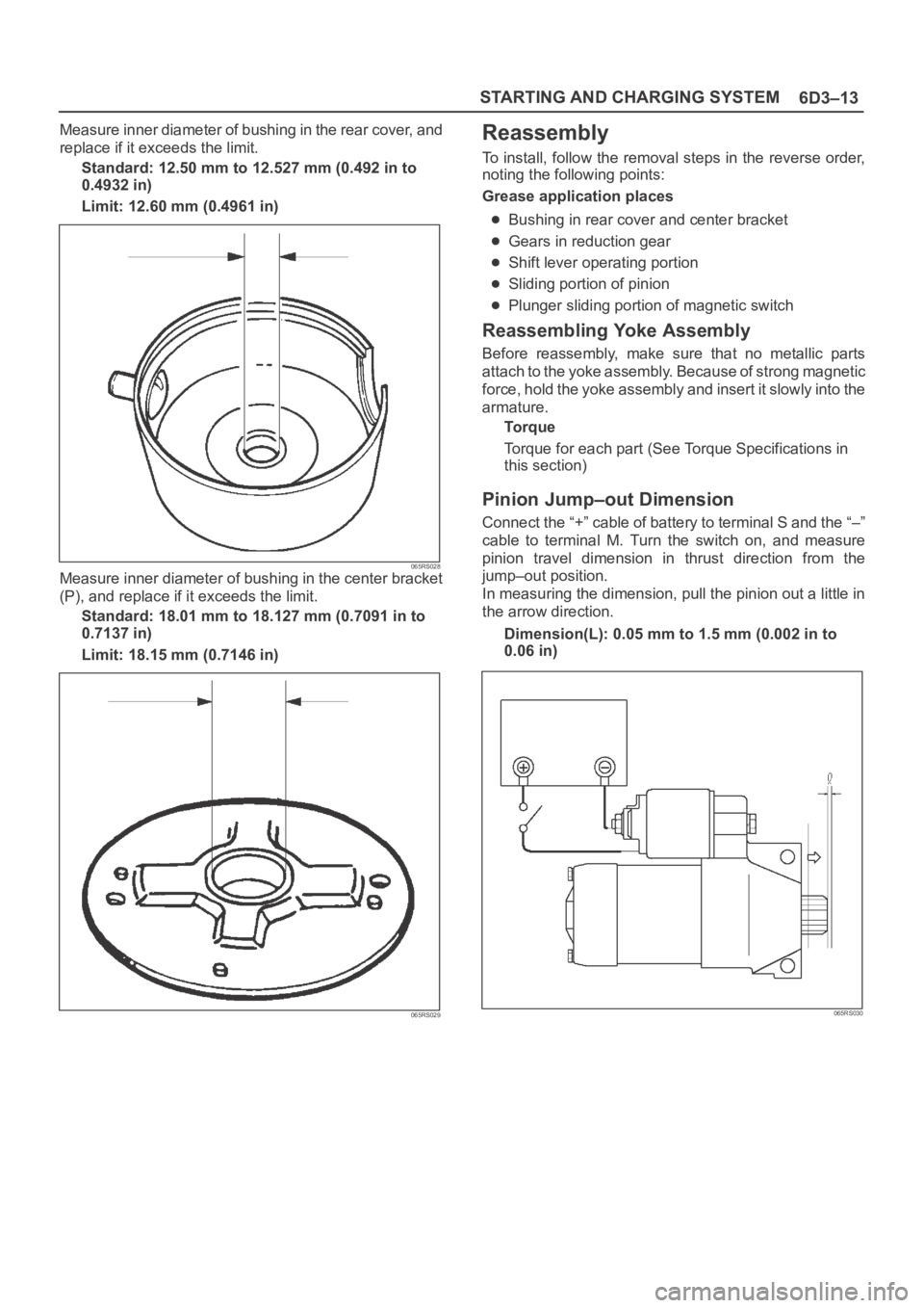
Measure inner diameter of bushing in the rear cover, and
replace if it exceeds the limit.
Standard: 12.50 mm to 12.527 mm (0.492 in to
0.4932 in)
Limit: 12.60 mm (0.4961 in)
065RS028Measure inner diameter of bushing in the center bracket
(P), and replace if it exceeds the limit.
Standard: 18.01 mm to 18.127 mm (0.7091 in to
0.7137 in)
Limit: 18.15 mm (0.7146 in)
065RS029
Reassembly
To install, follow the removal steps in the reverse order,
noting the following points:
Grease application places
Bushing in rear cover and center bracket
Gears in reduction gear
Shift lever operating portion
Sliding portion of pinion
Plunger sliding portion of magnetic switch
Reassembling Yoke Assembly
Before reassembly, make sure that no metallic parts
attach to the yoke assembly. Because of strong magnetic
force, hold the yoke assembly and insert it slowly into the
armature.
To r q u e
Torque for each part (See Torque Specifications in
this section)
Pinion Jump–out Dimension
Connect the “+” cable of battery to terminal S and the “–”
cable to terminal M. Turn the switch on, and measure
pinion travel dimension in thrust direction from the
jump–out position.
In measuring the dimension, pull the pinion out a little in
the arrow direction.
Dimension(L): 0.05 mm to 1.5 mm (0.002 in to
0.06 in)
065RS030
Page 4646 of 6000
6D3–15 STARTING AND CHARGING SYSTEM
Main Data and Specifications
General Specifications
ModelHITACHI GD002350
Rating
Voltage12 V
Output1.4 Kw
Time30 sec
Number of teeth of pinion 9
Rotating direction(as viewed from pinion)Clockwise
Weight(approx.)34 N
No load characteristics
Voltage /Current 11V/90A or less
Speed 2700rpm or more
Load characteristics
Voltage/current 8.4V/250A
Torque 7.3Nꞏm(64lbꞏin.) or more
Speed 1200rpm or more
Locking characteristics
Voltage/current 3V/750A or less
To r q u e19Nꞏm(14lbꞏin) or more
Page 4647 of 6000
6D3–16STARTING AND CHARGING SYSTEM
Torque Specifications
Nꞏm (Kgꞏm/lb ft)
E06RW044
Page 4650 of 6000

6D3–19 STARTING AND CHARGING SYSTEM
Generator
Removal
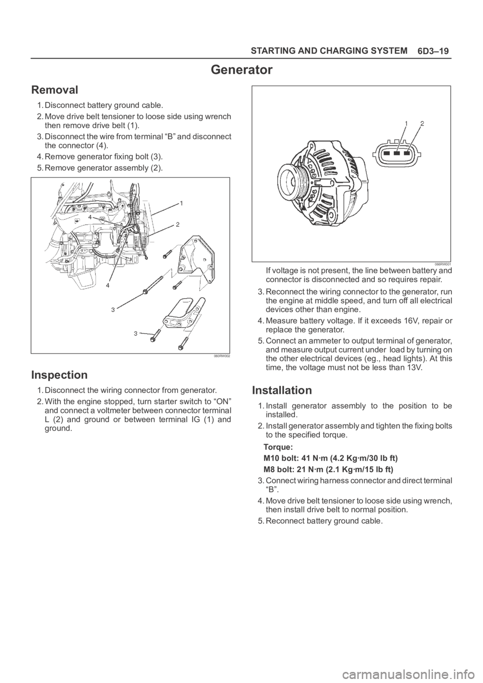
1. Disconnect battery ground cable.
2. Move drive belt tensioner to loose side using wrench
then remove drive belt (1).
3. Disconnect the wire from terminal “B” and disconnect
the connector (4).
4. Remove generator fixing bolt (3).
5. Remove generator assembly (2).
060RW002
Inspection
1. Disconnect the wiring connector from generator.
2. With the engine stopped, turn starter switch to “ON”
and connect a voltmeter between connector terminal
L (2) and ground or between terminal IG (1) and
ground.
066RW001If voltage is not present, the line between battery and
connector is disconnected and so requires repair.
3. Reconnect the wiring connector to the generator, run
the engine at middle speed, and turn off all electrical
devices other than engine.
4. Measure battery voltage. If it exceeds 16V, repair or
replace the generator.
5. Connect an ammeter to output terminal of generator,
and measure output current under load by turning on
the other electrical devices (eg., head lights). At this
time, the voltage must not be less than 13V.
Installation
1. Install generator assembly to the position to be
installed.
2. Install generator assembly and tighten the fixing bolts
to the specified torque.
To r q u e :
M10 bolt: 41 Nꞏm (4.2 Kgꞏm/30 lb ft)
M8 bolt: 21 Nꞏm (2.1 Kgꞏm/15 lb ft)
3. Connect wiring harness connector and direct terminal
“B”.
4. Move drive belt tensioner to loose side using wrench,
then install drive belt to normal position.
5. Reconnect battery ground cable.
Page 4656 of 6000
6D3–25 STARTING AND CHARGING SYSTEM
1. Using a press with a socket wrench attached,
reassemble rotor and rear end cover assembly in the
front cover.
066RS022
2. Install pulley on the rotor.
Secure the pulley directly in the vise between two
copper plates, and tighten nut to the specified torque.
Torque: 111 Nꞏm (11.3 Kgꞏm/82 lb ft)
066RS010
Bench Test
Conduct a bench test of the generator.
066RS023
Preparation
Remove generator from the vehicle (see “Generator
removal”).
1. Secure generator to the bench test equipment and
connect wires.
Terminal “IG” for energization
Terminal “L” for neutral (warning lamp)
Terminal “B” for output
2. Conduct the generator characteristic test.
Characteristics of generator are shown in illustration.
Repair or replace the generator if its outputs are
abnormal.
B06RW001
Page 4679 of 6000

6E–22
ENGINE DRIVEABILITY AND EMISSIONS
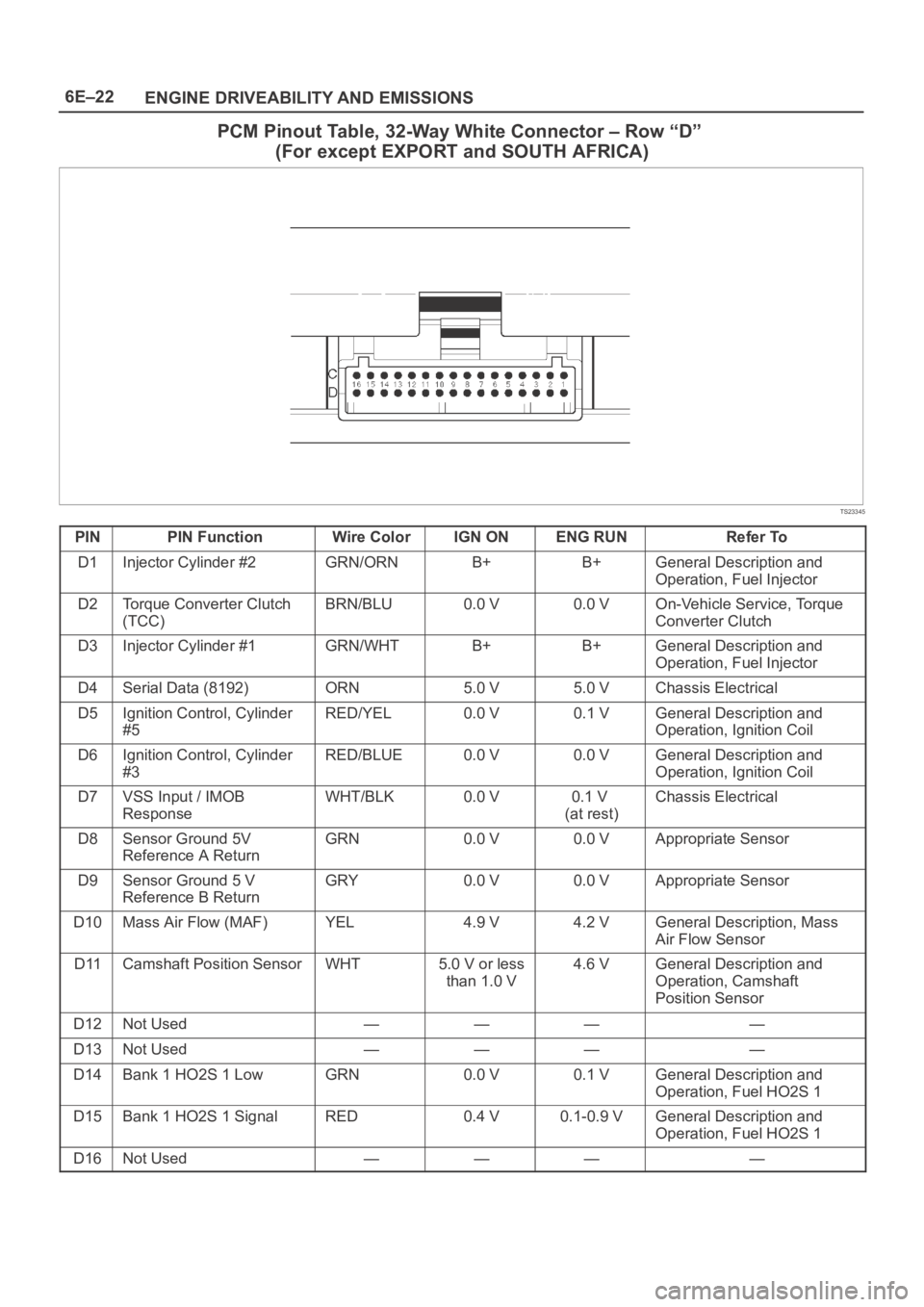
PCM Pinout Table, 32-Way White Connector – Row “D”
(For except EXPORT and SOUTH AFRICA)
TS23345
PINPIN FunctionWire ColorIGN ONENG RUNRefer To
D1Injector Cylinder #2GRN/ORNB+B+General Description and
Operation, Fuel Injector
D2Torque Converter Clutch
(TCC)BRN/BLU0.0 V0.0 VOn-Vehicle Service, Torque
Converter Clutch
D3Injector Cylinder #1GRN/WHTB+B+General Description and
Operation, Fuel Injector
D4Serial Data (8192)ORN5.0 V5.0 VChassis Electrical
D5Ignition Control, Cylinder
#5RED/YEL0.0 V0.1 VGeneral Description and
Operation, Ignition Coil
D6Ignition Control, Cylinder
#3RED/BLUE0.0 V0.0 VGeneral Description and
Operation, Ignition Coil
D7VSS Input / IMOB
ResponseWHT/BLK0.0 V0.1 V
(at rest)Chassis Electrical
D8Sensor Ground 5V
Reference A ReturnGRN0.0 V0.0 VAppropriate Sensor
D9Sensor Ground 5 V
Reference B ReturnGRY0.0 V0.0 VAppropriate Sensor
D10Mass Air Flow (MAF)YEL4.9 V4.2 VGeneral Description, Mass
Air Flow Sensor
D11Camshaft Position SensorWHT5.0 V or less
than 1.0 V4.6 VGeneral Description and
Operation, Camshaft
Position Sensor
D12Not Used————
D13Not Used————
D14Bank 1 HO2S 1 LowGRN0.0 V0.1 VGeneral Description and
Operation, Fuel HO2S 1
D15Bank 1 HO2S 1 SignalRED0.4 V0.1-0.9 VGeneral Description and
Operation, Fuel HO2S 1
D16Not Used————